-
Paper Information
- Paper Submission
-
Journal Information
- About This Journal
- Editorial Board
- Current Issue
- Archive
- Author Guidelines
- Contact Us
Electrical and Electronic Engineering
p-ISSN: 2162-9455 e-ISSN: 2162-8459
2018; 8(1): 24-28
doi:10.5923/j.eee.20180801.03

Delta-Sigma A/D Converters in Metrological versus Acoustic Applications
 Abstract
 Reference
 Full-Text PDF
 Full-text HTML
Tadeusz Sidor
University of Occupational Safety Management in Katowice, Katowice, Poland
Correspondence to: Tadeusz Sidor, University of Occupational Safety Management in Katowice, Katowice, Poland.
| Email: |  |
Copyright © 2018 Scientific & Academic Publishing. All Rights Reserved.
This work is licensed under the Creative Commons Attribution International License (CC BY).
http://creativecommons.org/licenses/by/4.0/

Delta-Sigma A/D converters are nowadays widely used in digital acoustic systems to record sounds and music. Such converters can also be used in measurement systems to convert analogue voltage signals to digital form. However quality requirements of converters used in measurement systems (Accuracy) and acoustic systems (S/N ratio) are different. The paper attempts to point out the differences in requirements for both kinds of applications.
Keywords: A/D converters, D-S modulators, Oversampling, Quantizing errors, S/N ratio
Cite this paper: Tadeusz Sidor, Delta-Sigma A/D Converters in Metrological versus Acoustic Applications, Electrical and Electronic Engineering, Vol. 8 No. 1, 2018, pp. 24-28. doi: 10.5923/j.eee.20180801.03.
Article Outline
1. Introduction
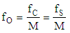
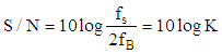
- Delta-Sigma Analogue to Digital Converters are nowadays extremely popular in various technical applications, mainly to convert analogue signals of music to digital samples for recording on CD disc, pen-drives or for digital radio signals. Such converters can also be used for various metrological applications. However the metrological applications require different and less rigorous properties of the converter than the one used in acoustic systems.The Delta-Sigma converters show certain unique feature which make them widely used in various applications. The Delta-Sigma modulators always produce much more samples that it is required to fulfill Shannon theorem i.e. working in oversampling state.Oversampling by itself spreads quantizing noise along frequency axis and significant part of it is cutoff by digital low pass filter. The one or more integrators within the modulator structure shape the remaining quantizng noise what increases S/N Signal to Noise ratio. Finally last but not least because sampling frequency is much higher than Shannon frequency band the design of analogue antyaliasing filter at the converter input is very simple.The basic structure of Delta -Sigma converter is presented in figure 1. The input signal is a voltage produced either by measuring transducer or acoustic amplifier. The modulator converts the input analogue signal of voltage to train of one bit (either 0 or 1) pulses, generated by clock of frequency fc = fS, which is much higher than minimum Shannon frequency 2fB required to convert analogue signal, of fB frequency band, into correct digital form. The ratio of fS to 2fB is called the oversampling ratio K (1).
 | (1) |
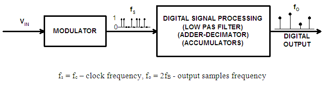 | Figure 1. Basic structure of Delta-Sigma converter |
2. Fundamental Structures of Delta-Sigma Converters
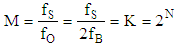
- In the simplest structure of Delta-Sigma converter the Digital Signal Processing unit can be in fact simple series input, parallel output digital counter. It can be shown that such a counter can serve as both digital low pass filter and decimator [1].The origin of Delta-Sigma A/D converter can be traced to synchronous voltage to frequency converter [2, 7] in its classical shape presented in figure 2.
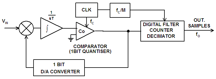 | Figure 2. Block diagram of A/D converter based on synchronous voltage to frequency converter |
 | (2) |
 | (3) |
 | (4) |
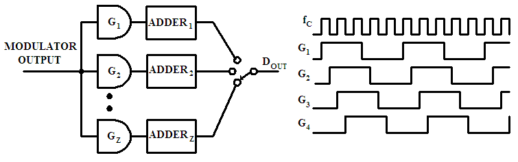 | Figure 3. The basic arrangement of parallel decimation system |
3. Metrological versus Acoustic Converters Properties
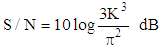
- Let us consider example data taken from AD 1871 chip specification. Sampling frequency fS = 13.288 MHz, 256 oversampling rate and 3 bit modulator comparator. It is sufficient to create 11 bit converter output samples with Shannon sampling frequency of 48 kHz. Using just two parallel adders the number of bits can be increased to 12.It might be sufficient for normal metrological application, but can not be taken for granted for converters used in acoustic systems.Let us to analyze and compare requirements of converter to be used in measurement systems and acoustic applications.In metrology transducers and converters accuracy is usually described by accuracy class index i.e. figure which describes in percents transducer limiting error related to its range. When input signal decreases the limiting error proportionally rises. It is common knowledge and when employing such device in measuring circuit care must be taken to set the magnitude of measuring signal as close to the converter range as possible. It usually satisfies the accuracy requirements as typical measuring signals have limited dynamic of 40 dB e.g. i.e.1: 100. The 12 bit converter distinguish 4096 signal levels, so the quantizing limiting error of ½ LSB is equivalent to 0.012%. Even if the magnitude of signal decreases to 10% of assumed maximum value, the relative errors rises only to 0.12%.It should be also mentioned that Shannon sampling frequency of 48 kHz is not often needed in normal industrial measurements. If the basic sampling frequency can be lover than the resolution of output samples can be increased.Completely different situation takes place when converter is used to proceed acoustic signal of music. Typical signal of that kind has dynamic of up to 120 dB i.e. 1: 1000000. This reflects the sensitivity of human ears which can receive sounds from quiet whisper to sounds of heavy metal bands. The errors of converter, in the shape of noise, should not be heard even when the signal is very low. Therefore the accuracy of converters used for digital acoustic systems is usually not expressed as limiting errors, but as signal to noise ratio S/N expressed in dB.To satisfy proper reception of acoustic signal of music converters used to convert analogue music signal to digital form, the converter should have the signal to noise ratio of similar order as dynamic range of music signal i.e. around 120 dB.It is not an easy task to achieve such a level, and various methods are used to make signal to noise ratio of A/D converters used for acoustic applications close to the required level.Fortunately the Delta-Sigma A/D converters have by themselves properties which increase signal to noise ratio: the oversampling, which is always present in Delta-Sigma converters and phenomenon of so called “noise shaping” thanks to the integrator(s) present in the converter feed-back loop (fig. 2).The basic formulae giving figures of S/N ratio for A/D converter of any kind are given in many papers e.g. [5, 6] and finally are presented in the form (5)
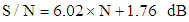 | (5) |
 | (6) |
 | (7) |
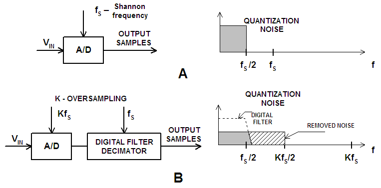 | Figure 4. The quantizing noise of any kind of A/D converter A, and effect of oversampling on decreasing the noise level B [3] |
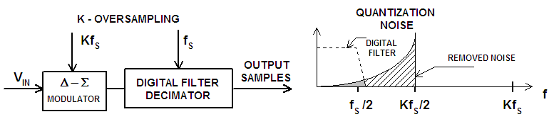 | Figure 5. The cumulative effect of oversampling and noise shaping for A/D converter with Delta-Sigma modulator on quantizing noise level [3] |
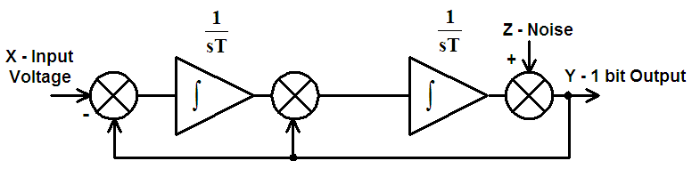 | Figure 6. Basic circuit diagram of Delta-Sigma modulator of second order |
4. Conclusions
- In several references [9-12] it is shown that noise shaping technique, implementation of comb-type decimalization output filters and other means which can, by using sigma – delta modulators of higher order, significantly improve signal to noise ratio, resulting in digital acoustic systems of better quality.There is no doubt that converters with first order delta modulators exhibit a periodical pattern of quantizing error in the output digital words which causes the appearance of idle tones when the converter is used in audio systems, and that the higher order modulators eliminate the problem by providing a kind of input signal dithering.However if the A/D converters based on sigma –delta modulators are used separately e.g. in measurement systems, it is not the level of noise, but rather the level of the limiting error which is of prime importance. All the published analysis does not consider the crux of the matter which is the uncertainty of converter digital output due to the quantizing error which is essential in metrological converter applications, but concentrate on pointing out that modulators of higher order are much better as they provide a higher signal to noise ratio. This may lead to the conclusion that higher order delta modulators used in analogue to digital converters somehow reduce the quantizing error of the conversion results.In order to determine the limiting errors of A/D converters that are used in measurement systems, time domain analysis can be used. This analysis, apart from being a natural tool for such an investigation, also gives physical insight into the complex processes taking place in sigma-delta modulators, particularly those of higher orders. Somehow the followers of Delta modulation use exclusively frequency analysis and time domain analysis is very seldom used although for metrological purposes it is essential.As it was mentioned previously A/D converters based on Delta Sigma modulators are today widely employed in acoustic digital systems to convert analogue sound signals into digital form. The digital samples are then recorded e.g. on CD, or transmitted through some kind of network. As digital signals, received or read from a CD, are converted back into an analogue voltage to drive amplifiers and speakers or headphones analysis of such system very often takes into account jointly A/D and D/A conversions which could lead to misunderstandings if this is not clearly specified.