-
Paper Information
- Previous Paper
- Paper Submission
-
Journal Information
- About This Journal
- Editorial Board
- Current Issue
- Archive
- Author Guidelines
- Contact Us
Electrical and Electronic Engineering
p-ISSN: 2162-9455 e-ISSN: 2162-8459
2017; 7(2): 65-68
doi:10.5923/j.eee.20170702.10

Superlative Vehicle
 Abstract
 Reference
 Full-Text PDF
 Full-text HTML
Jackson Ivan D’Souza, Oliver Lester Saldanha, Puneeth G. Suvarna, Theju Kumar JP, Sheryl Grace Colaco
Department of Electrical and Electronics Engineering, St Joseph Engineering College, Mangalore, Karnataka, India
Correspondence to: Jackson Ivan D’Souza, Department of Electrical and Electronics Engineering, St Joseph Engineering College, Mangalore, Karnataka, India.
| Email: |  |
Copyright © 2017 Scientific & Academic Publishing. All Rights Reserved.
This work is licensed under the Creative Commons Attribution International License (CC BY).
http://creativecommons.org/licenses/by/4.0/

Social and human demands promote the development of automobile technology. For general vehicles, the auxiliary driving or automated driving is from a safe and comfortable level to solve human driving requirements. As the growth of the social demand for cultural and health care, the demand is bound to be reflected during the vehicle driving. It is important to consider the driver who may be in fatigue, illness and disability. In this paper, we aimed to provide maximum customization satisfaction for all drivers by introducing three special and unique features particularly for existing vehicles along with the consideration of safety of drivers in emergency situations.
Keywords: ADD-automatic dim-dipper, Geo tagging, GPS and GSM module
Cite this paper: Jackson Ivan D’Souza, Oliver Lester Saldanha, Puneeth G. Suvarna, Theju Kumar JP, Sheryl Grace Colaco, Superlative Vehicle, Electrical and Electronic Engineering, Vol. 7 No. 2, 2017, pp. 65-68. doi: 10.5923/j.eee.20170702.10.
Article Outline
1. Introduction
- This project is focused on three special features namely ADD system, Smart braking system and Geo-Tagging system. ADD system keeps the correct head light lighting power in accordance with the opposite vehicle light or any light source intensity. By knowing the opposite vehicle light intensity value, the brightness of the light is varied. This system is accurate, reliable and provides comfort to all drivers during night time. Smart braking system used to keep the vehicle secure and protect it by the occupation of the intruders. Many accidents at High-ways are taking place due to the close running of vehicles, all of sudden, if the in front vehicle driver reduces the speed or applied breaks, then it is quite difficult to the following vehicle driver to control his vehicle, resulting accident. To avoid this kind of accident, Smart braking system comes into an effective use. After the occurrence of accident, many victims lost their lives because of failure of emergency treatment, this might be due to without passing proper information to a authorized people in a proper time. This can be avoided with the help of Geo-Tagging system.
2. System Overview
2.1. ADD System
- The density of vehicles on our roads rapidly increasing day by day. This forced almost all this vehicle manufactures to think about the extra safety derived in all road conditions. You must have come across this irritating situation while driving at night when you find the headlight lamps focus from an opposite vehicle falling straight in your eyes, making things difficult to assess, giving rise to a situation of a collision or some kind of possible accident. So naturally to get rid of this problem, an automatic mechanism has to come up to dip and dim the headlamp automatically whenever required.
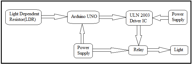 | Block Diagram of ADD System |
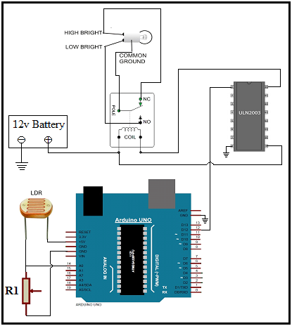 | Circuit Diagram of ADD System |
2.2. Smart Braking and Speed Control
- Every year many people lose their lives in accidents due to vehicles. One of the factor is due to inability of the driver to control the vehicle in an emergency situation. The purpose of this feature is to provide smart breaking and speed control. This system is designed using arduino microcontroller to control and provide the feedback to other hardware device.The main component of this project is the ultrasonic sensor and microcontroller. Output of the sensor is the distance between the vehicle or an obstacle which is in the form of PWM. The sensor gives a pulse for every increase in the distance. The arduino follows the program and gives the necessary output to the control of the driver circuit.IC L293D: It is a dual H-Bridge motor driver integrated circuit (IC). Motor drivers act as current amplifiers since they take a low-current control signal and provide a higher-current signal. This higher current signal is used to drive the motors.L293D contains two inbuilt H-bridge driver circuits. In its common mode of operation, two DC motors can be driven simultaneously, both in forward and reverse direction. The motor operations of two motors can be controlled by input logic at pins 2 & 7 and 10 & 15. Input logic 00 or 11 will stop the corresponding motor. Logic 01 and 10 will rotate it in clockwise and anticlockwise directions, respectively.Enable pins 1 and 9 (corresponding to the two motors) must be high for motors to start operating. When an enable input is high, the associated driver gets enabled. As a result, the outputs become active and work in phase with their inputs. Similarly, when the enable input is low, that driver is disabled, and their outputs are off and in the high-impedance state.
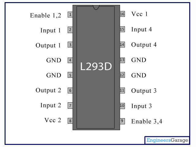 | Pin Diagram of IC L293D |
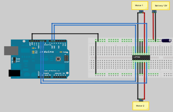 | Circuit Diagram for Smart braking |
2.3. Geo-Tagging
- The GPS receiver gets a signal from each GPS satellite. The satellites transmit the exact time the signals are sent. By subtracting the time the signal was transmitted from the time it was received, the GPS can tell how far it is from each satellite. The GPS receiver also knows the exact position in the sky of the satellites, at the moment they sent their signals. So given the travel time of the GPS signals from three satellites and their exact position in the sky, the GPS receiver can determine your position in three dimensions - east, north and altitude.
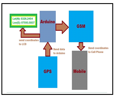 | Block Diagram of Geo-Tagging system |
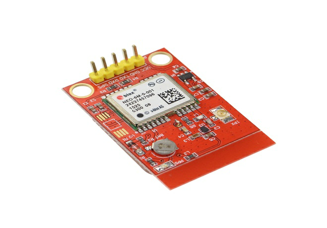
 | GPS Module |
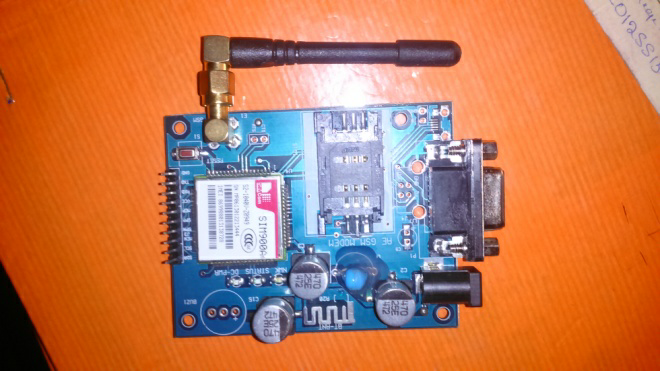
 | GSM Module |
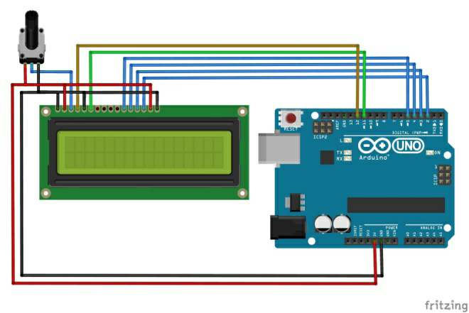 | LCD Interfacing |
3. Conclusions
- The superlative vehicle system developed can be implemented in the existing as well as emerging vehicles. The rate of accidents can be reduced by this system. Night driving is comparatively more preferred by using ADD system. Driver’s comfort is considerably improved. The speed control is very efficient by the use of ultrasonic sensor. The impact of Geo tagging in pour proposed project will enhance the reliability of the automobile system. It successfully reduces the number of deaths due to late attendance of the victims by sending the location to the authorized people.
ACKNOWLEDGEMENTS
- We owe our profound gratitude to the people whose kind consent and guidance helped us to complete this work successfully.We would also like to thank those who have always been with us extending their support, precious suggestions, guidance and encouragement throughout this work. Last but not the least we would like to thank Almighty God whose blessings facilitated the completion of our work.