-
Paper Information
- Next Paper
- Previous Paper
- Paper Submission
-
Journal Information
- About This Journal
- Editorial Board
- Current Issue
- Archive
- Author Guidelines
- Contact Us
Electrical and Electronic Engineering
p-ISSN: 2162-9455 e-ISSN: 2162-8459
2017; 7(2): 60-64
doi:10.5923/j.eee.20170702.09

Voice Operated Control of a Motor Using LabVIEW
 Abstract
 Reference
 Full-Text PDF
 Full-text HTML
Charlton Rodney D’Souza, Cedric Damien D’Souza, Sandeep Deepak D. Souza, Sanil D’Souza, Rolen Lionel Rodrigues
Department of Electrical and Electronics Engineering, St Joseph Engineering College, Mangalore, India
Correspondence to: Charlton Rodney D’Souza, Department of Electrical and Electronics Engineering, St Joseph Engineering College, Mangalore, India.
| Email: |  |
Copyright © 2017 Scientific & Academic Publishing. All Rights Reserved.
This work is licensed under the Creative Commons Attribution International License (CC BY).
http://creativecommons.org/licenses/by/4.0/

Main objective of this project is to use verbal communication as a medium to control the operation of the motor. Verbal communication can be done in English and to implement effective control of motors without the need of manual control. Its application is in irrigation for the people with partial disability, blind person etc. The salient feature of the motor is that it can be controlled both manually and by voice. The voice recognition and speech processing is done through LabVIEW graphical programming language.
Keywords: LabVIEW, myRIO, Speech recognition, PWM
Cite this paper: Charlton Rodney D’Souza, Cedric Damien D’Souza, Sandeep Deepak D. Souza, Sanil D’Souza, Rolen Lionel Rodrigues, Voice Operated Control of a Motor Using LabVIEW, Electrical and Electronic Engineering, Vol. 7 No. 2, 2017, pp. 60-64. doi: 10.5923/j.eee.20170702.09.
Article Outline
1. Introduction
- An electric motor is an electrical machine that converts electrical energy into mechanical energy. The reverse of this is the conversion of mechanical energy into electrical energy and is done by an electric generator. A DC motor's speed can be controlled over a wide range, using either a variable supply voltage or by changing the strength of current in its field windings. Small DC motors are used in tools, toys, and appliances. Larger DC motors are used in propulsion of electric vehicles, elevator and hoists, or in drives for steel rolling mills. For almost all the application of motors, it is essential for motor to have variable speeds. Control and variation of speed of motor is done by motor drives. The voice control of motors has a lot of potential applications. One of them is that it can be useful in the low visibility areas. It can be also used in autonomous vehicles and modern smart vehicles. The operations of motor that can be controlled by voice include turning on and turning off of motor, variation of speed of motor. The operation of motor is done by the voice of any person with language spoken being English. The speed control of motor is done through pulse width modulation method. Here we are using armature voltage control of motor. This kind of control is much more effective and efficient in operation of a motor in industrial and agricultural fields. The Power MOSFETs or IGBTs are used in the control circuit. Also, Gate Driver is used to drive the output of myRIO. TLP250 optocoupler gate driver is used for driving of gate pulse and isolation. The speech processing is done with the help of Laboratory Virtual Instrumentation and Engineering Workbench (LabVIEW) programming concepts. LabVIEW is a graphical programming language which makes it easier to code. The speech recognition is done using Microsoft Speech SDK. The Microsoft Speech Platform SDK 11 provides a comprehensive set of development tools for building voice-enabled applications that leverage Microsoft's redistributable speech engines. myRIO is used as the interfacing device for the voice input and LabVIEW programming. myRIO is used to develop applications that utilize its on-board FPGA and microprocessor. myRIO generates gate pulses, these pulses are given to the control circuit.
 | Figure 1. Block diagram of the V.O.C.A.L. |
2. DC Motors
- DC motor operates on the principle that when a current carrying is placed in a magnetic field, it experiences a mechanical force given by F = BIL newton. Where the current and ‘L’ is the length of the conductor. The direction of force can be found by Fleming’s left hand rule. There is no difference between a DC generator and DC motor in terms of Construction. Conversion of energy from electrical form to mechanical form by a DC motor takes place by the work done in overcoming the opposition which is called the back emf. DC motors can be classified depending on the type of excitation of field winding, the separately excited Dc motor and self-excited dc motor. Depending on the type of field winding connection DC machines can be further classified as series motor, shunt motor and compound motor. We will be using DC shunt motor for our application. The DC shunt motor has three important characteristics, they are Armature torque vs Armature current (Electrical characteristics), Speed vs armature current characteristic and Speed vs torque (Mechanical characteristics) [1].
3. Speed Control of DC Motors
- DC motors are in general much more adaptable speed drives than AC motors. Speed of a DC motor can be controlled in a wide range.
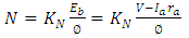 | (1) |
 | (2) |
3.1. Field Control
- In field control method field current is varied which varies the flux/pole (Ф) Limitations of speed control by field control: 1. ‘N’ below rated speed is not possible. Because Ф can be decreased and cannot be increased. 2. N α 1/ϕ and
 for a given armature current, this method suits for constant kW drives only where ‘T’ decreases if speed decreases. 3. Not suited for speed reversal [1].
3.2. Armature Voltage Control
- In this method, applied voltage across the armature of the DC motor is varied. This method is superior to field control in the following aspects: 1. This method provides a constant torque drive. (if the Ф and Ia are maximum, maximum torque can be obtained as
 ).2. Since main field ampere turns are maintained at large value, flux density distortion caused by armature reaction is limited.3. Unlike field control scheme, speed reversal can be easily implemented [1].
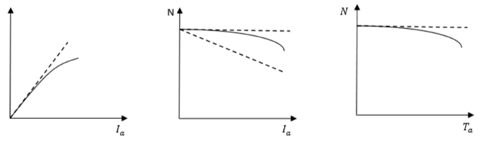 | Figure 2. Characteristics of DC shunt motor |
4. LabVIEW
- Laboratory Virtual Instrument Engineering Workbench (LabVIEW) is a system-design platform and development environment for a visual programming language from National Instruments. LabVIEW is commonly used for data acquisition, instrument control, and industrial automation on a variety of operating systems (OSs), including Microsoft Windows, various versions of Unix, Linux, and macOS [2]. LabVIEW is an integrated development environment designed specifically for engineers and scientists building measurement and control systems [3]. The programming language used in LabVIEW, named G, is a dataflow programming language. Execution is determined by the structure of a graphical block diagram (the LabVIEW-source code) on which the programmer connects different function-nodes by drawing wires. These wires propagate variables and any node can execute as soon as all its input data become available. LabVIEW integrates the creation of user interfaces (termed front panels) into the development cycle. LabVIEW programs-subroutines are termed virtual instruments (VIs). Each VI has three components: a block diagram, a front panel, and a connector panel. The last is used to represent the VI in the block diagrams of other, calling VIs. The front panel is built using controls and indicators. Controls are inputs: they allow a user to supply information to the VI. Indicators are outputs: they indicate, or display, the results based on the inputs given to the VI. The back panel, which is a block diagram, contains the graphical source code. All of the objects placed on the front panel will appear on the back panel as terminals. The back panel also contains structures and functions which perform operations on controls and supply data to indicators. The structures and functions are found on the Functions palette and can be placed on the back panel. Collectively controls, indicators, structures, and functions will be referred to as node [2]. LabVIEW is widely used in industries and research centers. LabVIEW has a wide spread use in engineering applications [4, 5].
4.1. MyRIO
- MyRIO is a real-time embedded evaluation board made by National Instruments. It is a real-time data acquisition and interfacing device [6]. It has in built FPGA processor, ADC, DAC, filters, timers and counters. myRIO is Wi-Fi compatible and hence it can be used as a wireless data acquisition device. It is used to develop applications that utilize its on-board FPGA and microprocessor. We use myRIO in this case to generate PWM signal and to acquire feedback signal [5].
 | Figure 3. LabVIEW front panel |
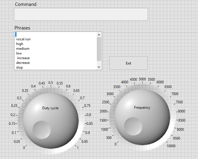
5. Pulse Width Modulation (PWM)
- Pulse-width modulation is a modulation process or technique used in most communication systems for encoding the amplitude of a signal right into a pulse width or duration of another signal, usually a carrier signal, for transmission. Although PWM is also used in communications, its main purpose is actually to control the power that is supplied to various types of electrical devices, most especially to inertial loads such as AC/DC motors. The average value of voltage (and current) fed to the load is controlled by turning the switch between supply and load on and off at a fast rate. The PWM switching frequency has to be much higher than what would affect the load (the device that uses the power), which is to say that the resultant waveform perceived by the load must be as smooth as possible. The rate (or frequency) at which the power supply must switch can vary greatly depending on load and application. The term duty cycle describes the proportion of 'on' time to the regular interval or 'period' of time; a low duty cycle corresponds to low power, because the power is off for most of the time. The main advantage of PWM is that power loss in the switching devices is very low. When a switch is, off there is practically no current, and when it is on and power is being transferred to the load, there is almost no voltage drop across the switch. Power loss, being the product of voltage and current, is thus in both cases close to zero [7]. PWM also works well with digital controls, which, because of their on/off nature, can easily set the needed duty cycle [8]. In this case PWM is generated in myRIO using simple LabVIEW Programs shown in fig 4.
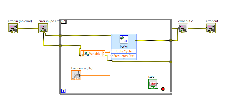 | Figure 4. Representation of PWM program |
6. IGBT Gate Driver
- The speed of the motor is controlled by using Pulse Width Modulation (PWM) method. The pulse is given to the gate of IGBT using a IGBT gate driver circuit. IC TLP250 is used in the IGBT gate driver circuit. The TLP250 is a optocoupler gate driver. TLP250 on its own is a low side driver. Pulse from myRIO is given to pin 3 of TLP250. From pin 7 or pin 6 the output is given to gate of the MOSFET or IGBT. The IC TLP250 requires 15V DC power supply. The MOSFET or IGBT is connected in series with the armature of the DC motor.
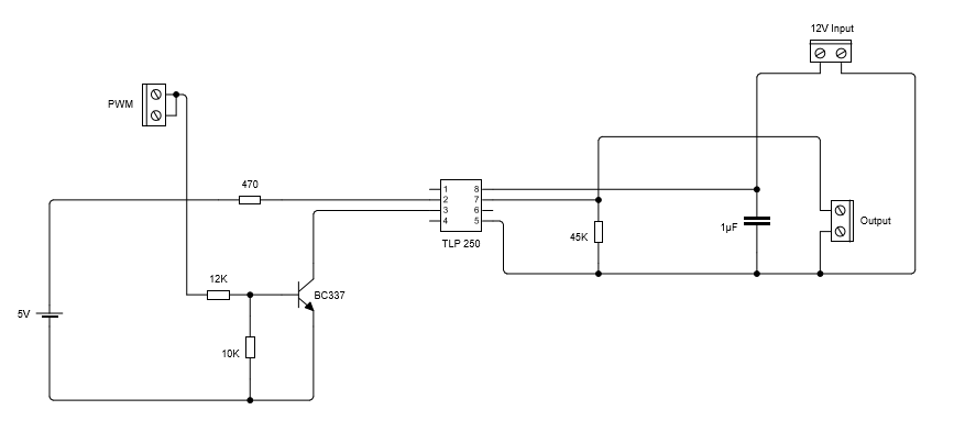 | Figure 5. IGBT gate driver circuit |
6.1. Isolation of Gate Signal
- Optocoupler driver IC TLP250 is used to provide electrical isolation between output of myRIO and gate of the IGBT. This ensures that the myRIO will not be damaged by the high voltages in the rest of the circuit.
7. Speech Recognition
- Speech recognition is the ability of a machine or program to identify words and phrases in spoken language and convert them to a machine-readable format. Speech recognition works using algorithms through acoustic and language modeling. Acoustic modeling represents the relationship between linguistic units of speech and audio signals; language modeling matches sounds with word sequences to help distinguish between words that sound similar. The most frequent applications of speech recognition within the enterprise include call routing, speech-to-text processing, voice dialing and voice search [9].
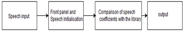 | Figure 6. Block diagram of speech recognition program |
7.1. Microsoft Speech SDK
- The Microsoft Speech Platform SDK 11 provides a comprehensive set of development tools for building voice-enabled applications that leverage Microsoft's redistributable speech engines. You can use the technologies and tools in the Speech Platform SDK 11 to give applications the ability to recognize spoken words (speech recognition) and to generate synthesized speech (text-to-speech or TTS). Using this SDK, you can give users an effective and natural way to interact with your applications, complementing the use of mice, keyboards, controllers, and gestures [10]. We will be using Microsoft speech SDK through LabVIEW programming for speech recognition.
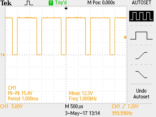 | Figure 7. Output of driver as viewed in DSO for 80% duty cycle |
7.2. LabVIEW Speech Programming
- The speech input is taken from either computer microphone input or myRIO microphone input. A list of phrases or words is initialized. The program responds only if these phrases or words are used. Speech recognition Grammar for theses phrases is build using the resources provided by Microsoft speech SDK. In order for speech recognition engine to return recognition from audio input, a grammar must be added to each speech control. A grammar is a representation of all the phrases a user will say with certain selections tagged with semantic properties and values. Here we are using Grammarbuilders and choices classes. The front panel and speech recognition engine is initialized. Speech recognition Grammar is loaded to the speech recognizer. A register is created for speech recognition event notification. After this the recognition starts. Several cases are created, if the recognition matches with any one of the case, the described action in the case is carried out [11]. This program is interfaced with the PWM program.
8. Conclusions
- The speed control of DC motor is achieved through speech recognition using LabVIEW and Microsoft SDK. The control of DC motor is implemented using pulse width modulation technique. The system has been tested on 0.5HP 220V 3A DC motor. The system was able to control the motor by using vocal commands of any person. The project has been successfully concluded.
ACKNOWLEDGEMENTS
- We would like to thank staff of Department of electrical and electronics engineering, St Joseph Engineering college for their support.