Divya K. Pai, Sheryl Grace Colaco
Electrical and Electronics Department, St Joseph Engineering College, Mangaluru, India
Correspondence to: Divya K. Pai, Electrical and Electronics Department, St Joseph Engineering College, Mangaluru, India.
| Email: |  |
Copyright © 2017 Scientific & Academic Publishing. All Rights Reserved.
This work is licensed under the Creative Commons Attribution International License (CC BY).
http://creativecommons.org/licenses/by/4.0/

Abstract
In order to have the reduced fuel consumption Engine speed at idle position should be low. But, since idle speed is set at low value, even slight fluctuations of the idle speed due to torque disturbances cause not only deterioration of vehicle performance but also unpleasant vibrations of the vehicle. Therefore, the primary goal of the idle speed control is to maintain a desired engine speed despite of torque disturbances. Dynamic modeling is an essential front end to control design. Sliding mode controller is designed for nonlinear engine (IC Engine) idle speed control. Simulation of the designed controller is carried out in MATLAB/SIMULINK. Simulink model of IC Engine is developed by interconnecting air, fuel and torque subsystems. The results indicate the ability to minimize idle speed variations under the rapid torque disturbances and the system nonlinearities/uncertainties.
Keywords:
Idle speed control, IC Engine model, Sliding mode control, Throttle
Cite this paper: Divya K. Pai, Sheryl Grace Colaco, Sliding Mode Idle Speed Control of IC Engine, Electrical and Electronic Engineering, Vol. 7 No. 2, 2017, pp. 52-59. doi: 10.5923/j.eee.20170702.08.
1. Introduction
The engine idle speed should be as low as possible for reduced fuel consumption. At low idle speed slight fluctuations of the idle speed due to torque disturbances could cause not only deterioration of vehicle performance but also unpleasant vibrations of the vehicle. Therefore, the primary goal of the idle speed control is to maintain a desired engine speed despite of torque disturbances. Automotive idle speed control (ISC) is a multivariable control issue. The selection of target idle speed corresponds to a tradeoff among fuel consumption, idle operation stability, and emission levels. On an average, about 30% of fuel consumption [2] in a city driving is spent at idle, and it continues to increase with increasing traffic levels. A reasonable target idle speed needs to be maintained in order to overcome mechanical frictions, misfiring, and load disturbances to prevent engines oscillation, vibration, hunting, and stalling under a variety of circumstances. At idle, both rich air to fuel (A/F) mixture and incomplete combustion are present due to in-cylinder residual gas fraction and low engine speed, giving rise to higher levels of HC and CO emissions. The primary goal of the ISC is to remain a desired engine speed despite of both the system nonlinearities/uncertainties and external torque disturbances due to the following reasons: air conditioning, power steering, alternator torque, and engagement of automatic transmission. In most vehicle engines while idling, the amount of air is controlled via a throttle bypass valve. The bypass valve also provides additional air during starting and prevents stalling as well as facilitates smooth transitions from higher engine speeds to idle speeds. In order to fulfill ISC system requirements model and control of IC Engine is necessary.Sliding mode control method has recently been developed as an alternative to linear control methods in number of application areas such as robotics and power plant control. It is a nonlinear controller design method that is directly applicable to set of nonlinear dynamic equations and directly considers the robustness to model errors and disturbance uncertainties in the design process. These features make this method highly desirable for designing a closed–loop controller.
2. Engine Dynamics
Three State Engine DynamicsThe engine model for a four stroke spark ignition engine was developed by Moskwa and Hedrick [6]. It was subsequently refined and used for different studies. The engine is continuous time model with three state variables given by,- the mass of air in intake manifold;- the engine speed;- mass flow rate of fuel entering combustion chamberThe following state equation is obtained by applying law of conservation of mass to the air flow in the intake manifold. | (1) |
Where,  = mass of air in the intake manifold;
  = mass rate of air in the intake manifold;
  = mass rate of air entering the intake manifold;
  = mass rate of air leaving the intake manifold and entering the combustion chamber. The mass rate of air entering the intake manifold (
 ) is given by,
 | (2) |
Where,  = the maximum flow rate corresponding to full open throttle, TC = Normalized Throttle characteristic, PRI = Normalized Pressure Influence function.Normalized Throttle characteristic is given by curve fit,
 | (3) |
Where α = the throttle angle.The Normalized Pressure Influence function PRI is calculated as a function of manifold to atmosphere pressure ratio and is given by curve fit, | (4) |
Where,  = intake manifold pressure,
  = atmospheric pressure. The intake manifold pressure
 and
and  the mass of air entering the intake manifold are modeled by ideal gas law,
  | (5) |
Where,  = Molecular weight of air, R =universal gas constant,
  = intake manifold temperature,
  = intake manifold volume. The flow of air from intake manifold to combustion
  chamber is given by,
 | (6) |
Where,  =engine angular velocity,
  = volumetric efficiency,
  is physical constant defined by,
  | (7) |
The volumetric efficiency  represents the effectiveness of engine’s induction process. The empirical formula is obtained from curve fit,
  | (8) |
The dynamics of the fuel injection process is modeled as follows, | (9) |
Where,  = fuel rate entering the combustion chamber,
  = command fuel rate,
  = effective fueling time constant, which is modeled as,
  | (10) |
Where,  = desired air/fuel ratio, MAX = the maximum flow rate corresponding to full open throttle.By applying Newton’s second law to the rotational dynamics of the engine the following equation is obtained,
 | (11) |
Where,  = effective inertia of the engine,
  = angular acceleration,
  = engine indicated torque,
  = engine friction torque,
  = accessories torque.In a four stroke engine, the process of torque production is discrete depending on the engine speed. The model used is continuous, thus two delays are introduced. The indicated torque is modeled by,
  | (12) |
Where,  = intake to torque production delay,
  = spark to torque production delay, AFI = normalized air fuel ratio influence function, SI = normalized spark influence function,
  = the maximum torque production capacity of an engine.The function, AFI is the normalized air fuel influence as a function of air to fuel ratio and is curve fitted from relation,
 | (13) |
Where A/F = actual air/fuel ratio of the mixture in the combustion chamber and is given by,  | (14) |
The function, SI is the normalized spark influence a function of spark advance/retard from MBT (minimum spark advance for best torque) and is curve fitted from relation,  | (15) |
Where, SA = tuning parameter representing the spark advance from Top Dead Center (TDC), MTB = the minimum spark advance from TDC for best torque. The engine friction torque is curve fitted from, | (16) |
Thus the engine model has three states  and three possible controls
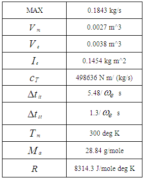
  .The parameter values of 4 stroke IC engine used for simulation are summarized in table 1.
Table 1. Simulation parameter values
 |
| |
|
3. Sliding Mode Control
A. IntroductionSliding mode control (SMC), is one of the effective nonlinear robust control approaches since it provides system dynamics with an invariance property to uncertainties once the system dynamics are controlled in the sliding mode. The gains in each feedback path switch between two values according to a rule that depends on the value of the state at each instant. The purpose of the switching control law is to drive the nonlinear plant’s state trajectory onto a pre-specified (user-chosen) surface in the state space and to maintain the plant’s state trajectory on this surface for subsequent time. The surface is called as switching surface. When the plant state trajectory is “above” the surface, a feedback path has one gain and a different gain if the trajectory drops “below” the surface. This surface defines the rule for proper switching. This surface is also called a sliding surface (sliding manifold). Ideally, once intercepted, the switched control maintains the plant’s state trajectory on the surface for all subsequent time and the plant’s state trajectory slides along this surface.The first step of SMC design is to select a sliding surface that models the desired closed-loop performance in state variable space. Then the control should be designed such that system state trajectories are forced toward the sliding surface and stay on it. The system state trajectory in the period of time before reaching the sliding surface is called the reaching phase. Once the system trajectory reaches the sliding surface, it stays on it and slides along it to the origin. The system trajectory sliding along the sliding surface to the origin is the sliding mode. The insensitivity of the control system to the uncertainties exists in the sliding mode, but not during the reaching phase. Thus the system dynamics in the reaching phase is still influenced by uncertainties.In sliding mode control the system structure is switched and the system state crosses the predetermined hyper-plane, so that the system slides along the reference trajectory. The resultant characteristic of the system may become far different from those of the original system and it has been known that the system becomes to be immune to the parameter variations and disturbances. In an ideal system, the switching frequency can be very high and the state slides smoothly on the reference trajectory. In real systems however, such as digital control systems the switching rate should be limited. Accordingly the system state chatters around the sliding line and the limit cycle occurs even in the steady state.The typical structure of sliding mode controller is composed of a nominal part, and of additional terms aimed at dealing with modeling uncertainty (parametric uncertainty or unmodeled dynamics) intuitively this method is based on the fact that it is much easier to control 1st order systems, be they non linear or uncertain, than it is to control nth order system.The following is simple introduction to sliding mode control method [1].Following single input dynamical system is considered, | (17) |
Where x is the output of interest, u is the control and f(x) and b(x) are nonlinear functions. | (18) |
 | (19) |
 | (20) |
 | (21) |
The sliding surface s (t) is defined by the scalar equation s(x,t)=0, where | (22) |
Given  the problem of trajectory tracking is equivalent to that of remaining on the sliding surface s(t) for all t≥0. If there is an initial condition mismatch, the control u should be designed so as to get the trajectory on the surface s (t). Once on the sliding surface, the dynamics are governed by equations (4.6), which represent a stable dynamical system with (n-1) Eigen values at –λ. If u keeps the trajectory on the sliding surface, asymptotic trajectory tracking can be achieved. Thus, the problem of tracking the dimensional vector
  can in effect be replaced by a 1st order stabilization problem in s (i.e. selection of u to keep s=0). Since the expression of s contains x(n-1), differentiation should be carried only once for u to appear. (In other words, the choice of s has resulted in a system with relative degree 1). Following lyapunov function is considered for the design of u,
  | (23) |
The derivative of this lyapunov function along with the trajectories of the system (4.1) is given by,  | (24) |
The choice of s is such that, the input u appears in the equation for  | (25) |
Therefore making  negative definite. This makes the surface makes s(t)=0 stable and attractive. The control law which achieve (8) results in high frequency chattering near the sliding surface s=0. High frequency chattering is undesirable as it needs large bandwidth actuators and reduces the life of the components.B. Controller DesignThe sliding mode control (SMC) scheme is a nonlinear controller design method that is directly applicable to a set of nonlinear dynamic equations and directly considers the robustness to model errors and disturbance uncertainties in the design process. These features make this scheme highly desirable for designing a closed-loop throttle controller. The SMC scheme considered is a kind of tracking control [1]. The object of the scheme is to keep the engine at a desired idle speed. To keep the design problem tractable, time delays are not taken into consideration and robustness properties of the sliding mode controller takes care of the mismatch.Sliding surface is designed as,
 | (26) |
 = engine speed,
  = desired engine speed.Differentiating equation 4.11
 | (27) |
Substituting for  ,
, | (28) |
Where, | (29) |
By using state equation for  in (2.1), the following equation is obtained,
 | (30) |
 | (31) |
Solving equation (14) and (17), the following equation is obtained, | (32) |
The above equation gives the desired TC value. The throttle characteristic is inverted to get the desired throttle angle, | (33) |
4. Results and Conclusions
A. Simulation resultsThe support software for simulation of the designed controller is MATLAB/SIMULINK under the assumption that the air-to-fuel ratio is of 14.7 (i.e., stoichiometric ratio). For the simulation, the specified closed throttle position is of 0.5 radians and the spark advance is assumed at 1 radians (i.e., MBT), and the idle speed should be maintained at about 100 radians/second under the external engine load torque disturbances. The simulation results are shown in the figures 1 to 8. The idle speed of the engine with no controller drops from 100rps to 19.36rps as shown in figure 3. But, the engine with the throttle-only controller has a small drop in the idle speed as shown in figure 7. This amounts to no more than about 50rps. Chattering problems occur at the boundary layer when sliding mode control is implemented as shown in figure 7.B. Responses without sliding mode controller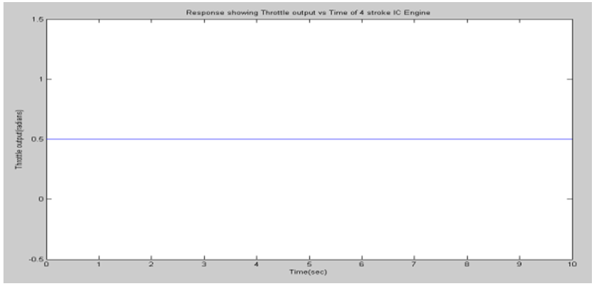 | Figure 1. Response showing throttle output |
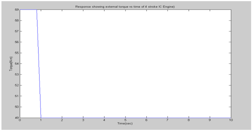 | Figure 2. Response Torque Vs Time of 4 stroke IC Engine |
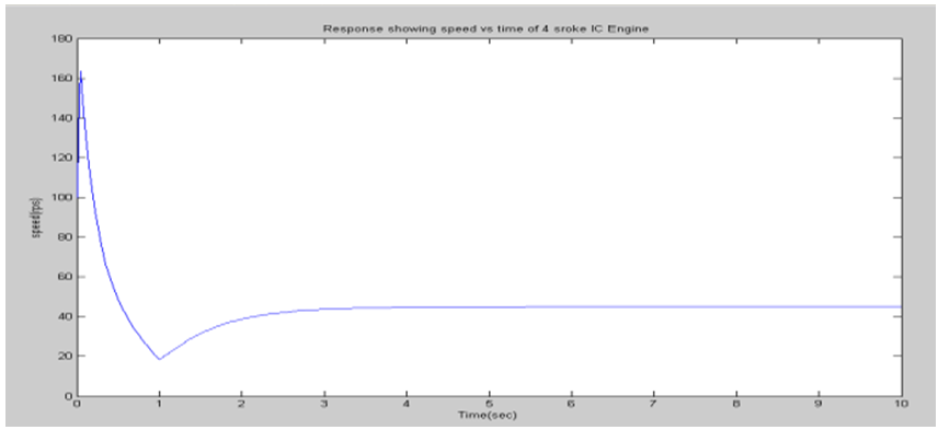 | Figure 3. Response of Speed Vs Time of 4 stroke IC Engine |
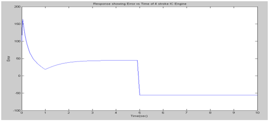 | Figure 4. Response of Error Vs Time of 4 stroke IC Engine |
C. Responses with sliding mode controller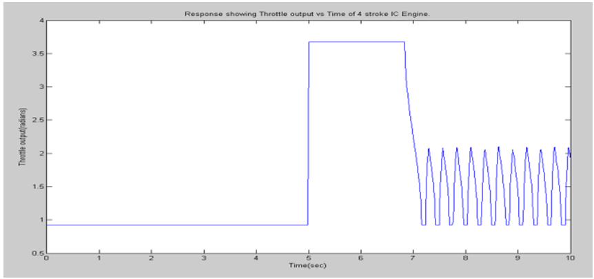 | Figure 5. Response showing throttle output |
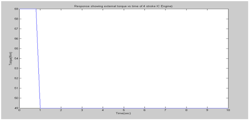 | Figure 6. Response of Torque Vs Time of 4 stroke IC Engine |
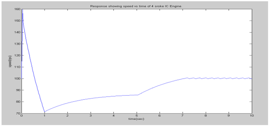 | Figure 7. Response of Speed Vs Time of 4 stroke IC Engine |
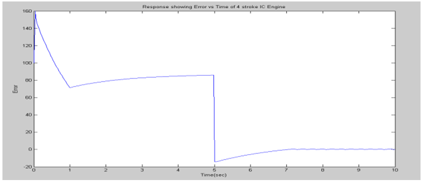 | Figure 8. Response of Error Vs Time of 4 stroke IC Engine |
5. Conclusions
1. IC Engine dynamics are so nonlinear that linearized perturbation equations and linear models have very limited validity, and as a result, closed loop controller designs based on linear models will inevitably lead to “gain scheduling”. Therefore sliding mode controller is designed for nonlinear engine idle speed control which has superior ability to minimize idle speed variations under the rapid torque disturbances and the system nonlinearities/uncertainties.2. Simulation of the designed controller is carried out in MATLAB/SIMULINK and responses with and without sliding mode controller is compared.3. It is observed that the idle speed of the engine with no controller drops from 100rps to 19.36rps. But, the engine with the throttle-only controller has a small drop in the idle speed and chattering problems occur at the boundary layer.4. Thus, it is evident that the proposed sliding mode idle speed control system has superior ability to minimize idle speed variations under the rapid external torque disturbances.
References
| [1] | Datta Godbole and Sinan Karahan, “Automotive Powertrain Modeling, Simulation and Control Using Integrated Systems Case Tools”, SAE paper, No.940180, 1994. |
| [2] | Hrovat and Jing Sun, “Models and control methodologies for IC engine idle speed control design”, Control Engineering Practice, Volume 5, Issue 8, August 1997, Pages 1093-1100. |
| [3] | D. Cho and J.K Hedrick, “Automotive Powertrain Modeling for Control’’, ASME Journal of Dynamic Systems, Measurement and Control, volume 111, pp568- 576, 1989. |
| [4] | Cho and J.K Hedrick, “A Nonlinear Controller Design Method For Fuel-Injected Automotive Engines’’, ASME Journal of Engineering for Gas Turbines and Power, Volume 110, pp313- 320, 1988. |
| [5] | R. Sarvanakumar, K. Vinoth Kumar and Dr. K. K. Ray, “Sliding Mode Control of Induction Motor Using Simulation Approach”, IJCSNS International Journal of Computer Science and Network Security, Volume 9, No.10, October 2009. |
| [6] | Moskwa, J. J. and Hedrick, J. K., “Nonlinear Algorithms for Automotive Engine Control”, IEEE Control System Magazine, Volume 10, No. 3, pp. 88-93, April 1990. |
| [7] | J. Moskwa and J.K. Hedrick, “Modeling and validation of automotive engines for control algorithm development”, ASME Journal of Mechanisms, Transmission and Automation in Design, Volume 114, no.2, pp. 278-285, 1992. |
| [8] | R.W. Weeks and J.J. Moskwa, "Automotive Engine Modeling for Real-time Control Using MATLAB/SIMULINK", SAE paper, No. 950417, 1995. |
| [9] | I. Utkin, “Sliding Mode Control Design. Principles and Applications to Electric Drives”, IEEE Transactions. Industrial. Electronics, Volume 40, No. 1, pp. 23-26, February 1993. |


 = mass of air in the intake manifold;
  = mass rate of air in the intake manifold;
  = mass rate of air entering the intake manifold;
  = mass rate of air leaving the intake manifold and entering the combustion chamber. The mass rate of air entering the intake manifold (
 ) is given by,
 = the maximum flow rate corresponding to full open throttle, TC = Normalized Throttle characteristic, PRI = Normalized Pressure Influence function.Normalized Throttle characteristic is given by curve fit,

 = intake manifold pressure,
  = atmospheric pressure. The intake manifold pressure
 and
and  the mass of air entering the intake manifold are modeled by ideal gas law,
 = Molecular weight of air, R =universal gas constant,
  = intake manifold temperature,
  = intake manifold volume. The flow of air from intake manifold to combustion
  chamber is given by,
 =engine angular velocity,
  = volumetric efficiency,
  is physical constant defined by,
 represents the effectiveness of engine’s induction process. The empirical formula is obtained from curve fit,

 = fuel rate entering the combustion chamber,
  = command fuel rate,
  = effective fueling time constant, which is modeled as,
 = desired air/fuel ratio, MAX = the maximum flow rate corresponding to full open throttle.By applying Newton’s second law to the rotational dynamics of the engine the following equation is obtained,
 = effective inertia of the engine,
  = angular acceleration,
  = engine indicated torque,
  = engine friction torque,
  = accessories torque.In a four stroke engine, the process of torque production is discrete depending on the engine speed. The model used is continuous, thus two delays are introduced. The indicated torque is modeled by,
 = intake to torque production delay,
  = spark to torque production delay, AFI = normalized air fuel ratio influence function, SI = normalized spark influence function,
  = the maximum torque production capacity of an engine.The function, AFI is the normalized air fuel influence as a function of air to fuel ratio and is curve fitted from relation,


 and three possible controls
  .The parameter values of 4 stroke IC engine used for simulation are summarized in table 1.


 the problem of trajectory tracking is equivalent to that of remaining on the sliding surface s(t) for all t≥0. If there is an initial condition mismatch, the control u should be designed so as to get the trajectory on the surface s (t). Once on the sliding surface, the dynamics are governed by equations (4.6), which represent a stable dynamical system with (n-1) Eigen values at –λ. If u keeps the trajectory on the sliding surface, asymptotic trajectory tracking can be achieved. Thus, the problem of tracking the dimensional vector
  can in effect be replaced by a 1st order stabilization problem in s (i.e. selection of u to keep s=0). Since the expression of s contains x(n-1), differentiation should be carried only once for u to appear. (In other words, the choice of s has resulted in a system with relative degree 1). Following lyapunov function is considered for the design of u,


 negative definite. This makes the surface makes s(t)=0 stable and attractive. The control law which achieve (8) results in high frequency chattering near the sliding surface s=0. High frequency chattering is undesirable as it needs large bandwidth actuators and reduces the life of the components.B. Controller DesignThe sliding mode control (SMC) scheme is a nonlinear controller design method that is directly applicable to a set of nonlinear dynamic equations and directly considers the robustness to model errors and disturbance uncertainties in the design process. These features make this scheme highly desirable for designing a closed-loop throttle controller. The SMC scheme considered is a kind of tracking control [1]. The object of the scheme is to keep the engine at a desired idle speed. To keep the design problem tractable, time delays are not taken into consideration and robustness properties of the sliding mode controller takes care of the mismatch.Sliding surface is designed as,
 = engine speed,
  = desired engine speed.Differentiating equation 4.11
 ,
,

 in (2.1), the following equation is obtained,


 Abstract
 Reference
 Full-Text PDF
 Full-text HTML