-
Paper Information
- Next Paper
- Previous Paper
- Paper Submission
-
Journal Information
- About This Journal
- Editorial Board
- Current Issue
- Archive
- Author Guidelines
- Contact Us
Electrical and Electronic Engineering
p-ISSN: 2162-9455 e-ISSN: 2162-8459
2017; 7(2): 48-51
doi:10.5923/j.eee.20170702.07

Automatic Voltage and Frequency Control of a Diesel Generator using NI myRIO
 Abstract
 Reference
 Full-Text PDF
 Full-text HTML
Joylon Cornelio, Anish D’Souza A., Basil Baby, Ismail Musharaf Hasan, Franco A. Menezes
Department of Electrical and Electronics Engineering, St Joseph Engineering College, Mangalore, Karnataka, India
Correspondence to: Joylon Cornelio, Department of Electrical and Electronics Engineering, St Joseph Engineering College, Mangalore, Karnataka, India.
| Email: |  |
Copyright © 2017 Scientific & Academic Publishing. All Rights Reserved.
This work is licensed under the Creative Commons Attribution International License (CC BY).
http://creativecommons.org/licenses/by/4.0/

The proposed project is a system to regulate the output voltage and frequency of a diesel generator using the NI myRIO programmed in LabVIEW. A motor-generator set, comprising of a three phase alternator directly coupled to a DC shunt motor, is used to demonstrate the working of the system. Two Class A choppers are used to control the field currents of both machines. The modifications required to retrofit the system to existing diesel generators, irrespective of size, are relatively simple and few.
Keywords: Alternator, LabVIEW, myRIO, Automatic Voltage Regulator, PID control, PWM, Chopper
Cite this paper: Joylon Cornelio, Anish D’Souza A., Basil Baby, Ismail Musharaf Hasan, Franco A. Menezes, Automatic Voltage and Frequency Control of a Diesel Generator using NI myRIO, Electrical and Electronic Engineering, Vol. 7 No. 2, 2017, pp. 48-51. doi: 10.5923/j.eee.20170702.07.
Article Outline
1. Introduction
- Diesel engine driven generators are used extensively in commercial and industrial establishments as backup power sources, especially in India. In a typical diesel generator, the output voltage varies with load and is also quite distorted. Moreover, the speed of the generator also changes considerably with load and hence the frequency varies. Due to these factors, the power quality of diesel generators is quite poor.The proposed project is a system to regulate the output voltage and frequency of a diesel generator using the NI myRIO programmed in LabVIEW. A motor-generator set, comprising of a three phase alternator directly coupled to a DC shunt motor, is used to demonstrate the working of the system. This is due to the non-availability of a diesel generator, and the cost involved in acquiring one just for this project.
2. System Overview
2.1. Theory of Operation
- The speed of a DC motor depends on load, armature voltage and field current. Hence, for a given load and armature voltage, speed can be controlled by controlling it’s field current. For an alternator, the frequency of the armature terminal voltage is a function of its speed, while its magnitude depends on speed, field current and armature current. Since the shafts of both machines are directly coupled, the speeds of both machines are the same. Therefore controlling the field currents of both machines gives us control over both the output voltage as well as the frequency [1].
2.2. Field Current Control
- A typical diesel generator is self-excited, i.e., the alternator’s field winding is fed from its own armature through a rectifier. Thus, in the proposed project, the alternator’s field winding is fed through a chopper drawing power from the alternator’s armature through a rectifier. However, the DC motor’s field is fed by another chopper supplied by the same DC source as its armature.
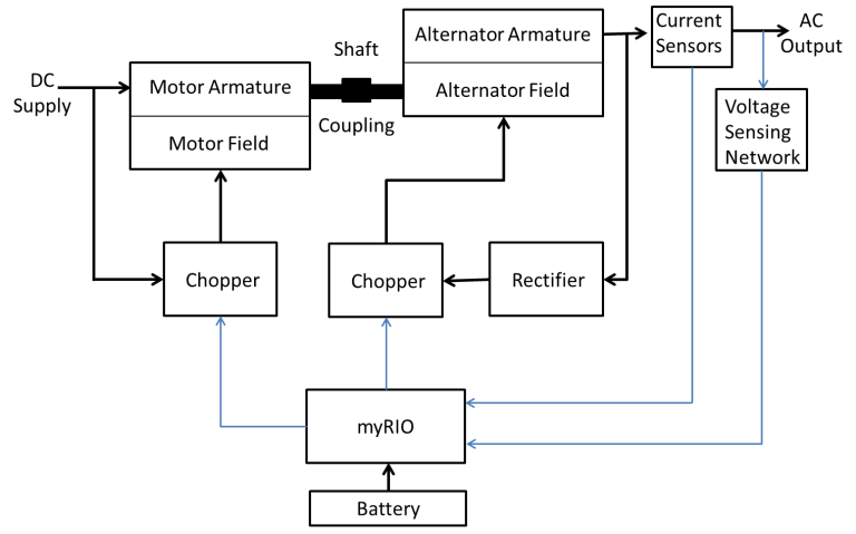 | Figure 1. Block diagram of the system |
2.3. Control Hardware and Software
- The myRIO is the system controller. The myRIO (Reconfigurable Input Output) is an embedded device which contains a dual core ARM Cortex A9 processor and a Xilinx FPGA. It has 40 digital I/O pins, 10 analog inputs and 8 analog outputs [2]. The myRIO is programmed in LabVIEW. LabVIEW is an integrated development environment for a graphical programming language developed by National Instruments [3]. It is designed specifically for engineering and scientific applications like measurement, signal processing and control systems [4, 5].
3. System Components
3.1. Electrical Machines
- DC Shunt Motor: 220V, 16A, 1500rpmAlternator: 5KVA, 415V, 3-Ø, 50Hz Excitation voltage: 200V
3.2. Choppers
- The choppers are both simple Class A choppers, as shown in figs 2 and 3. The motor field chopper consists of a single MOSFET (IRF740) and a fast recovery diode (UF4007). The generator field chopper uses FQPF7N80C MOSFETs and a pair of the same diodes connected in parallel. It is fed from a three phase full wave rectifier (with a capacitor filter) drawing power from the alternator armature. The rectifier consists of six 1N4007 rectifier diodes and the filter has four 150uF, 450V capacitors connected as shown. The gates of the MOSFETs are driven by two IR2110 gate drive ICs.
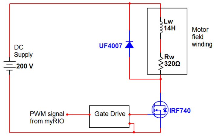 | Figure 2. Motor field chopper |
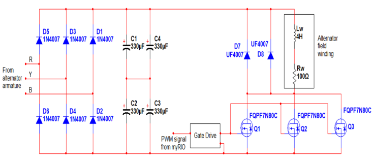 | Figure 3. Alternator field chopper |
3.3. Sensing Networks
- Hall Effect current sensors (ACS712) are used to sense motor and alternator armature and field currents. Three 230V/4.5V transformers connected in star-star are used to sense the three phase output voltages.
3.4. Protective Circuitry
- Overcurrent protection is provided for both the motor and the alternator. If an overcurrent is sensed in the motor input current or in any of the three phases of the alternator, the motor is isolated from its supply and the alternator is isolated from the load. The system is a latching type, i.e., once it has tripped, it cannot be reset until the motor armature rheostat (connected to limit starting current) is in the maximum position.
4. Selection of Components
4.1. Selection of Sensors
- Hall Effect current sensors were chosen considering the need for isolation between the various circuits of the system. The motor is rated for 16A and the alternator armature is rated at 7A RMS. Hence, 20A sensors were chosen for the motor armature current and the output three phase line currents. 5A sensors were chosen for the field currents as lower range Hall Effect sensors were not available.For ac voltage measurements, the 230V/4.5V, transformers were chosen, as transformers with lower secondary voltages were not easily available. As they are not expected to supply any significant load, transformers with the lowest available current rating (0.5A) were chosen.
4.2. Selection of Switching Frequency
- A low switching frequency is desirable from the point of view of MOSFET switching losses and gate drive circuit stress. Higher frequency switching means a smoother current waveform and lower torque ripples [6]. Hence, the switching frequency chosen must balance these conflicting requirements. The motor field winding has massive inductance of 14H. Due to the inertia of the rotating parts, the speed and torque are not significantly affected by moderately high ripple currents in the field winding. Hence, a switching frequency of 1 KHz in the motor field chopper would provide adequate performance. The alternator field winding has a lower inductance of 4H. Here, the current waveform needs to be much smoother to ensure a good armature output waveform. Hence, switching is performed at 5 KHz for the alternator field chopper.
4.3. Selection of Power Electronic Components
- The motor field chopper is supplied from a 200V dc supply and must handle a maximum current of 620mA. Hence, the IRF740, with a drain-source breakdown voltage of 400V and an RDS(ON) of 550mΩ, was chosen. Conduction losses at 620mA are 210mW. At 1 KHz, switching losses are assumed to be low, and the total loss is not expected to exceed 500mW. Hence, a single MOSFET with a small heat sink is used.The alternator output is fed to a three phase full wave rectifier. The maximum current required from the rectifier is 1.6A, which corresponds to an average current of about 550mA per diode. The maximum reverse voltage across the diodes is the peak of the line voltage (590V). Hence, 1N4007 diodes, which have a PIV of 1KV and maximum average current of 1A, were chosen.The rectifier feeds the alternator field chopper. The power switch chosen for the chopper must handle a peak voltage of 590V and current of 1.6A. Hence, two FGA25N120 IGBTs, with a collector to emitter breakdown voltage of 1200V and collector to emitter saturation voltage of around 1.5V at 1.6A, are paralleled. Conduction loss per device is 1.2W. Considering switching losses, the total loss per device is estimated to be a little more than 2W. Hence, the IGBTs are mounted on a single large heat sink with a fan for cooling.Due to the inductive nature of the windings, freewheeling diodes are absolutely essential. The diodes chosen must be able to handle the peak currents and voltages, and must also be able to switch at the chosen switching frequency. Hence, UF4007 ultrafast recovery rectifier diodes, with PIV rating of 1 KV, continuous current rating of 1A, and reverse recovery time of 75ns, were chosen. The motor chopper uses only one diode. The alternator chopper uses two in parallel due to its higher current requirement.
5. Signal Conditioning
5.1. Current Sense Signal Conditioning
- The output voltage of the current sensors is given byVCS=ZCO+S*Iwhere ZCO = Zero Current Offset, i.e., the voltage when the current through the sensing element is zero, S is the sensitivity of the sensorI is the current through the channelAccording to the datasheet, ZCO = 2.5V, S=185mV/A for 5A sensors and 100mV/A for 20A sensors. Practically, it was found that the value of ZCO varies between 2.48V to 2.54V, and is not fixed for a given sensor. Also, since the sensitivity is very low, the noise in the circuit affects measurements considerably, causing errors of ±800mA, as shown in fig 4. To eliminate noise in current measurements, op-amp based active filters are used.
5.2. Transformer Voltage Signal Conditioning
- The myRIO’s ADC can sense voltages between 0 to 5V. The transformer output voltages swing between 7V to -7V. Hence, both scaling and offset are required before the signals can be fed to the myRIO. Each transformer’s output is scaled to ±1.5V using resistive voltage dividers. An offset of 2.5V is provided using a KA431 precision shunt regulator. This offset voltage is connected at the neutral of the star connected secondary windings. Hence, the voltages at the analog inputs of the myRIO swing between 1V to 4V.
6. Control Algorithm
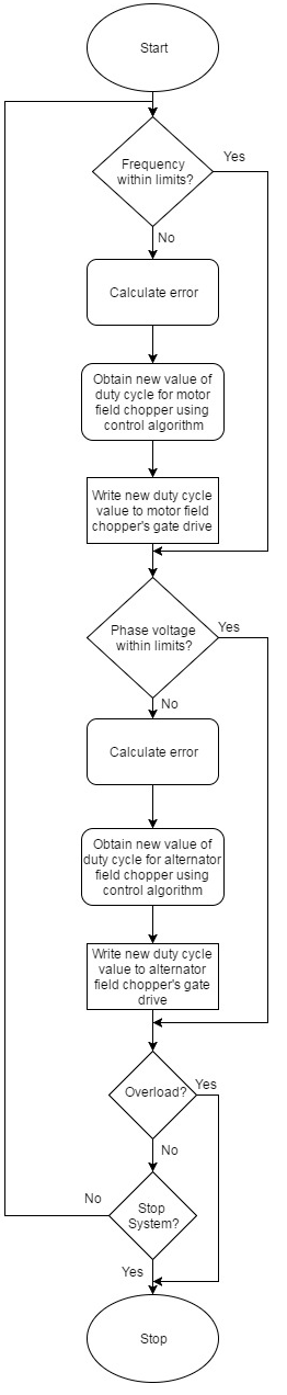
- The control system consists of two independent subsystems: voltage control and frequency control.
 | Figure 6. Basic block diagram of the system |
6.1. Voltage Control
- The voltage control system continuously monitors the RMS values of voltages of all three phases. The necessary corrective action is taken by changing the duty cycle of the alternator field chopper.
6.2. Frequency Control
- Alternator output frequency is calculated by measuring the time between zero crossings of the output voltages. Corrective action is taken by adjusting the duty cycle of the motor field chopper.
6.3. Pulse Width Modulation (PWM)
- The signals fed to the gate drive circuits are square waves with a duty cycle determined by the control program. For Class A choppers, a higher duty cycle corresponds to a higher current in the circuit. Hence, the current in the circuit can be controlled by the width of the pulses given to the drive circuit. This method of control is called Pulse Width Modulation (PWM).
7. Conclusions
- An automatic voltage and frequency regulation system was implemented with a PID algorithm with a myRIO programmed in LabVIEW. Class A choppers, controlled through PWM, were used for field current control. The system improved the alternator’s frequency regulation from ±1.5Hz to ±0.5Hz and voltage regulation from ±30V to ±10V.