-
Paper Information
- Next Paper
- Previous Paper
- Paper Submission
-
Journal Information
- About This Journal
- Editorial Board
- Current Issue
- Archive
- Author Guidelines
- Contact Us
Electrical and Electronic Engineering
p-ISSN: 2162-9455 e-ISSN: 2162-8459
2017; 7(2): 24-27
doi:10.5923/j.eee.20170702.03

Concept of Solar and Pedal Powered Electric Bicycle
 Abstract
 Reference
 Full-Text PDF
 Full-text HTML
Sathisha K., Deepesh S. Kanchan
Electrical & Electronics Department, St Joseph Engineering College, Mangaluru, India
Correspondence to: Sathisha K., Electrical & Electronics Department, St Joseph Engineering College, Mangaluru, India.
| Email: |  |
Copyright © 2017 Scientific & Academic Publishing. All Rights Reserved.
This work is licensed under the Creative Commons Attribution International License (CC BY).
http://creativecommons.org/licenses/by/4.0/

Global warming and scarcity of traditional resources are becoming major problems in the current scenario. Due to the economic challenges India is facing in the automotive sector, the hybrid bicycle market has a huge growth potential. The main objective is that it can be used in remote or rural places, where the energy generated by pedaling is utilized to motor the cycle during commute. It makes use of the abundantly available solar energy which makes it a viable means to travel as well as a means to light up houses. The proposed model consists of a Solar panel, PMDC machine and a detachable battery. The motor is connected to the bicycle through suitable chain drive system. An electronic controller assists the control of the vehicle speed, charge output of the panel and prevents battery discharge when not in use. It inherits protection logic for voltage and current fluctuations and prevention of overcharging of battery during generation. It can also be charged using an AC supply when not in use. This project simplifies riding with minimal effort on flat paths as well as gradients. In addition to this, solar energy utilization and hybrid economy ensures a cleaner and more economical solution to the energy crisis. Boost converter raises the generator output of 6V to13V as input to the battery with 80% duty cycle.
Keywords: PV Panel, Buck-Boost Converter, DC Motor
Cite this paper: Sathisha K., Deepesh S. Kanchan, Concept of Solar and Pedal Powered Electric Bicycle, Electrical and Electronic Engineering, Vol. 7 No. 2, 2017, pp. 24-27. doi: 10.5923/j.eee.20170702.03.
1. Introduction
- The current trend in the power sector is to change societies dependent on fossil fuels, to a world opting for alternate renewable resources, for their energy requirements, so as to conserve the natural energy [1, 2]. Soon the world is going to be depleted of all - nonrenewable resources, like oil and gas reserves, if the world's demand for energy from fossil fuels continues at the present rate. This idea is an example of replacing conventional vehicles used for transportation, which are dependent on fuel, with a more cost effective and environment friendly system, dependent on electricity, since it is the most efficient non-polluting source of energy known to man-kind today.
2. Materials and Methods
- Cycle: A normal gearless cycle is required to generate the power; it is being used as a prime mover, and also as the means of transportation [3, 4].DC machine: A 200W DC machine is used to convert electrical energy to mechanical energy and vice-versa. The power from the rotation of the pedal is fed to the battery through this DC machine. And it rotates the wheel during motoring.Solar Panel: This 30W 12V Panel converts solar energy to electrical energy and supplies it to the battery. It is equipped with a charge controller which prevents battery from overcharging.Battery: The 12V battery stores the energy in electrical form, it is supplied charge from the solar panel and DC machine working as generator. Since it is detachable, we can use the charge in it for non-transportation purposes also. Sprocket-chain gear assembly: This mechanism allows us to run the shaft of the generator at rated speed of 1500rpm from the normal riding speed of the bicycle; and vice-versa.Mechanical Switching: There is a DPDT switch, which enables the rider to go to motoring mode when there is charge in the battery and also allows the system to trip the battery while the charge is below specified limits. Acceleration control is optional.The AC step-down Rectifier circuit at power frequency is used to charge the battery to full capacity (12V) while parked near AC mains plug point. The step-down transformer brings down the value of voltage from 230V to 12V, while the rectifier circuit converts it into regulated and filtered DC 12V. It is then fed into the battery through the power electronic protection circuit. The circuit prevents the battery from overcharging by tripping the supply once it is fully charged, and also gives an indication. Now the bicycle is ready to be motored. On travelling, the motor can be switched on, by the user, whenever its assistance for riding is required and the power electronic circuit supplies the charge of the battery to the motor. There is a decrease in charge when motoring takes place. Now in case the rider is going down-hill or speeding up in a level road, he can switch over to generation by pedaling action by using the circuit buttons provided. Now the DC machine can act as a generator, supplying the lost charge back to the battery during commute. This action also happens only until battery reaches full charge.In case the battery is fully discharged on commuting, using the motoring action for a long time, the circuit prevents it from motoring further until sufficient charge is built-up in the battery again.The solar panels also charge the battery through the charge controller whenever sufficient light intensity falls on it. This action can happen when the cycle is parked under direct sunlight. The charge controller is used to regulate the output of the panel which keeps varying, so that the battery is charged uniformly by the panel, until full-charge. This product can also be used as a generator, by supplying the charge to an empty battery during commute and through solar panels, and then removing the detachable battery with its circuit we can supply the charge to household equipment like bulbs and fans. Figure 1 and figure 2 shows block diagram of the proposed method and model of solar and pedal powered electric bicycle respectively.
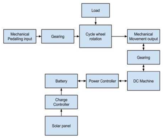 | Figure 1. Block Diagram of the solar and pedal powered bicycle |
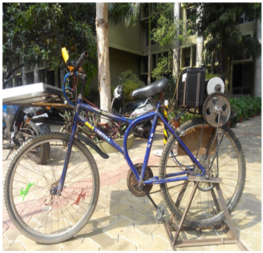 | Figure 2. Model of Solar and Pedal Powered Electric Bicycle |
3. Results and Discussions
- Various tests were conducted on the DC machine, and experimental results were tabulated before and after mounting the circuitry on the bicycle. The following are the graphs and their explanation showing the various characteristics of the machine.DC Motor Characteristics:Brake test on the DC machine by applying varied load on the shaft of the motor gave the results as tabulated below. It was inferred that there is a decrease in the terminal voltage of the machine as the current through the motor increases owing to the resistance of the winding. Fig. 3 depicts the characteristics for two different trials.
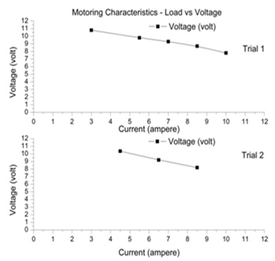 | Figure 3. Motoring characteristics |
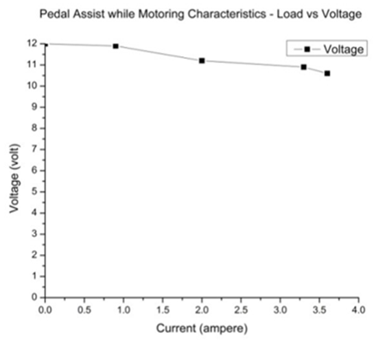 | Figure 4. Pedal assist while Motoring Characteristics |
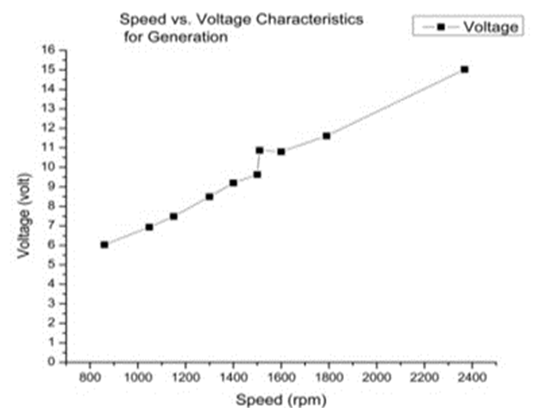 | Figure 5. Generation characteristic |
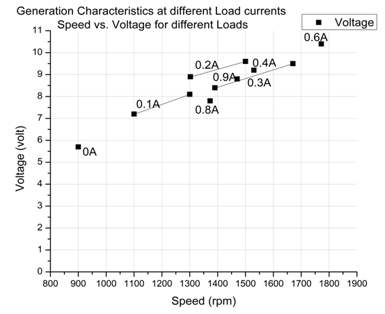 | Figure 6. Generated voltage vs. speed at different load currents |
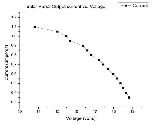 | Figure 7. Solar panel output current vs. voltage |
4. Conclusions
- The pedal and solar powered electric bicycle was tested on level, inclined and drooping roadways of Vamanjoor with satisfactory results. The innovative component of the developed model is the use of regenerative braking and use of solar panel to ride an electrically motorized bicycle. Under motoring mode and level road conditions, the DC machine mounted on the bicycle exhibits an overall conversion efficiency of 85% for a single rider with a top speed of 15kmph without pedal power in use. This higher conversion efficiency is attributed to the fact that the permanent magnet DC motor was used which eliminated the field copper losses. In generating mode, the bicycle was able to generate 35 watts of power going downhill and the solar panel gives a variable output in the range of 12 Watts (dawn) to 17 Watts (midday) which continuously charges the battery.The product could incorporate monitoring and display devices which could help the rider to change from generation to motoring modes and vice versa. It is possible to use a hub motor instead of a permanent magnet DC motor as it does not need extra gear sprocket arrangement. This reduces the overall weight of the system. A small wind energy generator can be incorporated as an auxiliary system into the bicycle mainframe so that it can add up with the main generating system to charge the battery.