Lavanya H., Pradeep Kumar
Department of Electrical and Electronics, NMAMIT, Nitte, Karkala Taluk, India
Correspondence to: Lavanya H., Department of Electrical and Electronics, NMAMIT, Nitte, Karkala Taluk, India.
| Email: |  |
Copyright © 2017 Scientific & Academic Publishing. All Rights Reserved.
This work is licensed under the Creative Commons Attribution International License (CC BY).
http://creativecommons.org/licenses/by/4.0/

Abstract
A Single phase load compensation with grid interface without using PLL is presented in this paper. Power factor correction with reduced harmonics with maximum power point tracking is main objective of the paper. Instead of PLL a notch filter is used to synchronize the frequency for grid connection. The need of PI controller reduces due to removal of PLL and using notch filter, which interns increases the stability and robustness. MATLAB software is used to simulate the concept.
Keywords:
Solar photovoltaic system, Harmonics mitigation, Phase locked loop, Notch filter, Grid
Cite this paper: Lavanya H., Pradeep Kumar, Grid Interfaced Load Compensating Solar PV Generation System without using PLL, Electrical and Electronic Engineering, Vol. 7 No. 2, 2017, pp. 18-23. doi: 10.5923/j.eee.20170702.02.
1. Introduction
Photovoltaic (PV) single-stage inverters are winding up noticeably more appealing as for twofold phase models because of their minimization, ease and unwavering quality. As of late, utilization of sustainable power source, for example, photovoltaic, wind energy and energy component are ending up plainly more prominent. A PV framework changes over daylight into power. The primary target of designer needs to decrease the two major drawbacks of solar PV generation, it's named as moderate efficiency and other one is intermittent nature.The issue of moderate efficiency is reduced by utilizing MPPT systems to extract maximum power from PV modules. A converter is used to transfer the maximum power from PV framework. Three sorts of MPPT procedures are there. In this paper P&O algorithm is used. It gives constant perturbation of PV model's voltage and current. It compares the measured parameters before and after the perturbation at MPP. Another drawback of PV power is intermittent nature. This can be overcome by utilizing power network as energy buffer. The control algorithm permits the power zero voltage direction, voltage regulation and maximum power can be extracted from PV panel.The nonattendance of PLL decreases the framework dependency on PI controller tuning, which in turn enhances the dynamic response of the framework. The proposed paper predominantly focuses on the control algorithm for single phase grid tied VSC. The notch filter is used to estimate unit vectors and to estimate active power component of load current.
2. Block Diagram of the System
The block diagram of proposed system is shown in fig 1. In this system a power electronic dc-dc boost converter is used to extract the maximum power from PV modules and transfer this power to grid.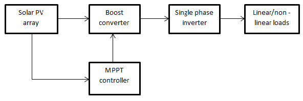 | Figure 1. Block Diagram |
PV panel can be outlined by the rating requirement. PV panel is interfaced with boost converter. DC-DC Boost converter duty cycle is obtained by P&O MPPT algorithm. Boost converter is interfaced with single stage inverter with power grid and load. This framework is intended to get most extreme power for PV array and transfer it to the grid while getting local load responsive power request and eliminating harmonics which is created by nearby nonlinear loads.
3. Proposed System
The system arrangement of the twofold stage single phase grid interfaced solar PV system is appeared in Fig.2. The framework has two power stages that use power electronics converters to produce the maximum power from the solar PV modules and transfer it to the grid. PV array will be designed according to the rating requirement the of PV module. PV array is interfaced with a boost converter. The duty cycle of boost converter is obtained by P&O algorithm, ensuring MPP operation. The boost converter is interfaced to a voltage source converter through a DC link capacitor. The VSC is interfaced with the local load; grid and a ripple filter, through an AC inductor at the point of common coupling. The grid frequency and grid voltage are kept to be constant. The load can be linear and nonlinear in nature. The system setup is made to extract the maximum power from the PV array and that power is transfer to the grid, while compensating the power demand and reducing harmonics that produced by local load. The detail of control algorithm developed for the system is explained in chapter 3. The variable "ipv" is the PV array current and "vpv" is the PV array voltage.  is the current entering the PCC from the VSC. Grid current is denoted by
  and load current is denoted by
  . PCC voltage is denoted by
  .
.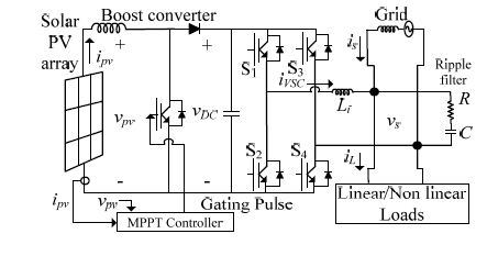 | Figure 2. Proposed system of the double-stage single-phase grid connected solar PV system |
4. Control Algorithm
The control strategy consists of two stage, MPPT control block and control of single phase VSC.
4.1. Text Maximum Power Point Tracking (MPPT)
The issue of MPPT has been tended to in various routes in the writing be that as it may, particularly for ease usage, the annoy and watch (P&O) maximum power point following algorithm is the most generally used strategy because of its simplicity of implementation. A PV cell voltage and power is used as a contribution to the P&O MPPT controller which gives the duty cycle of boost converter to track MPP and creates control signal to DC-DC boost converter. This signal contrasted and saw-tooth waveform and the output signal controls the duty cycle of DC-DC boost converter with a specific end goal to track maximum power from sun based PV panel.
4.2. Control of Single Phase VSC
VSC control block is shown in below fig.2. This VSC control block can be controlled by determining (‘iL’) in-phase component of load current, magnitude of real component of load current (‘ILp’), amplitude of the PCC voltage (‘Vsp’) and switching losses of VSC. 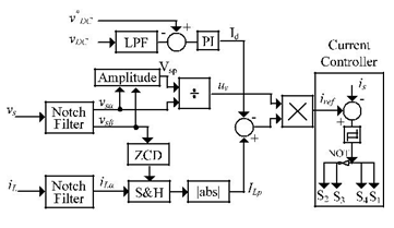 | Figure 3. VSC Control Block |
To In-phase current can be calculated by designing notch filter which doesn’t contain any harmonics. Magnitude of real component can be determined by using 90° out of phase component PCC voltage, ZCD, a sample and hold logic.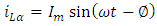 | (4.1) |
 | (4.2) |
 | (4.3) |
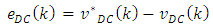
To calculate a unit template, ‘uv’ the following equation is used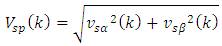 | (4.4) |
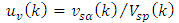 | (4.5) |
Current signal for PI controller can be calculate by using following equation, | (4.6) |
 | (4.7) |
‘Kp’ is proportional gain and ‘Ki’ is integral gains of PI controller respectively.The PI controller output is subtracted from magnitude of load current. The present signal is then synchronized with the grid voltage by multiplying it with unit template  of PCC voltage to produce reference framework current. At that point reference signal is subtracted from detected grid current to produce error signal. At that point this current is contrasted and the upper and lower edge at each testing moment.In this paper rather than PLL a notch filter is used to remove the harmonic part of load current. The absence of PLL decreases the framework dependency on PI controller tuning, which enhances the dynamic response of the framework and furthermore it make the framework very robust. A notch filter is intended to concentrate harmonic free component of load current. The frequency of grid is kept constant. The system outline is appeared in fig.4.
  | Figure 4. Block Diagram of Notch filtering |
5. Matlab Based Simulation Studies
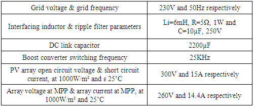
The proposed twofold phase single-stage grid connected sun oriented PV framework is modeled using MATLAB/SIMULINK. The model is simulated with the parameter as shown in the table 1 below.Table 1. System Parameter
 |
| |
|
The simulation model of proposed system is appeared in figure 5. PV modules are planned by the rating requirement. P&O algorithm produce the duty cycle for DC-DC boost converter. Reference grid current can be gotten by VSC control block.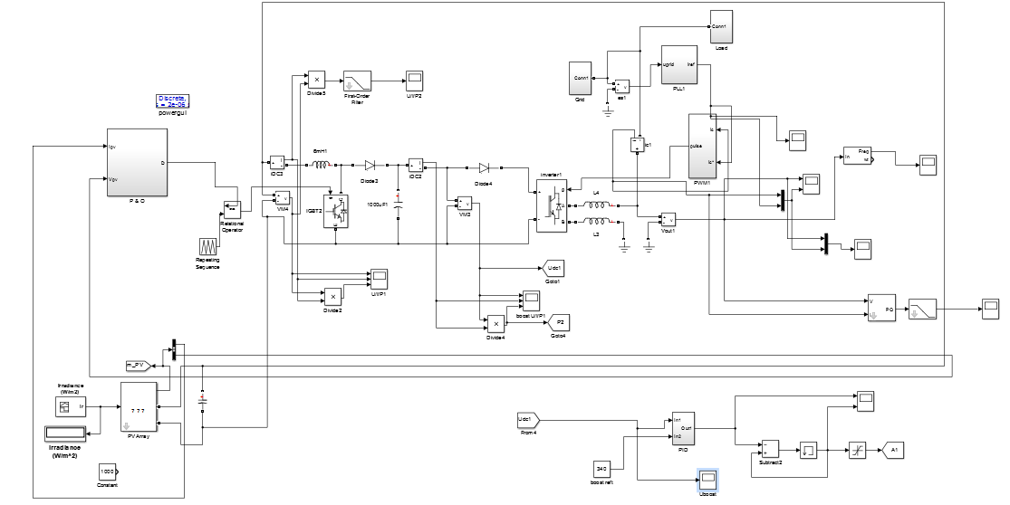 | Figure 5. Simulation model of twofold phase single-stage framework |
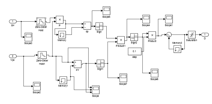 | Figure 6. P & O MPPT simulation model |
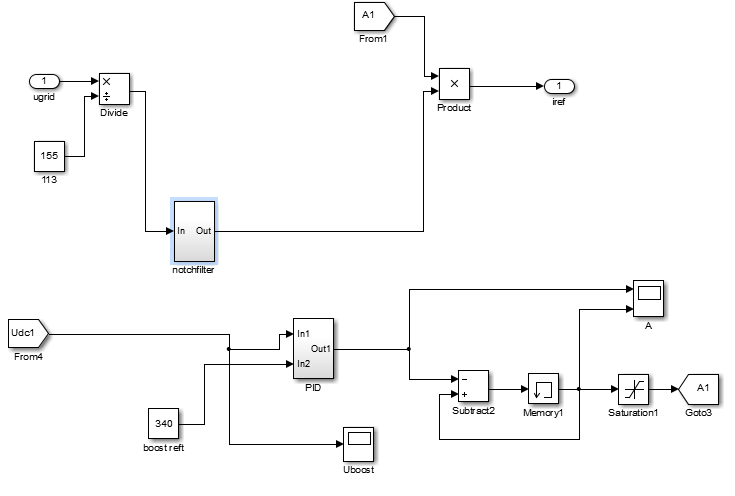 | Figure 7. VSC simulation model |
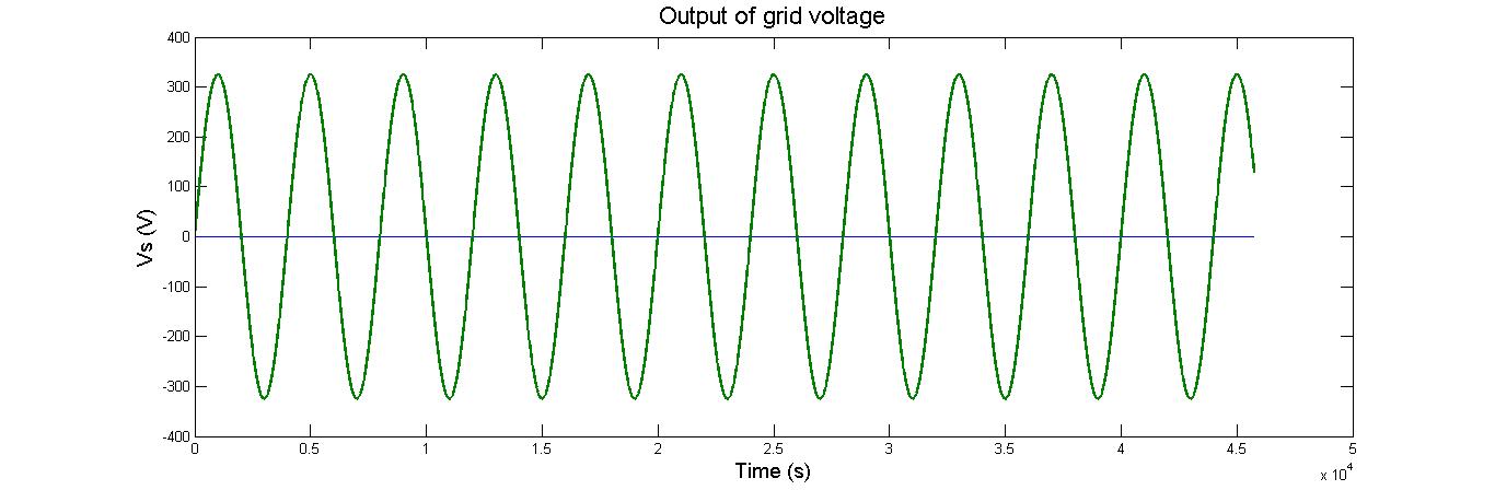 | Figure 8. Output of Grid Voltage |
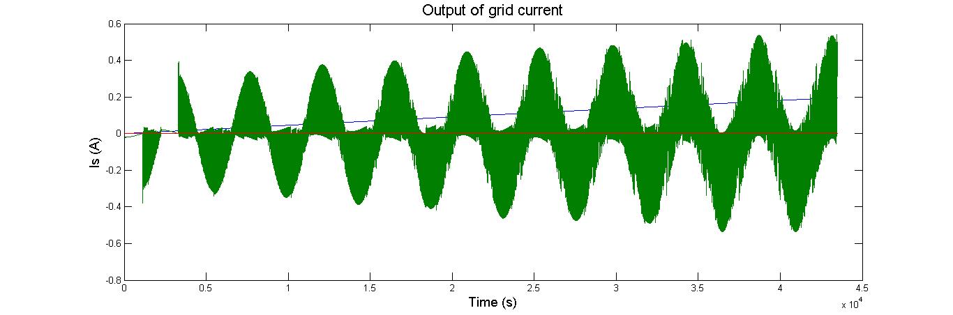 | Figure 9. Output of Grid current |
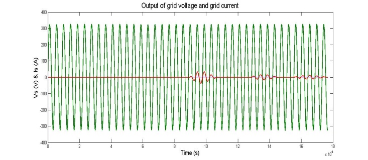 | Figure 10. Output of Grid Voltage and Grid Current |
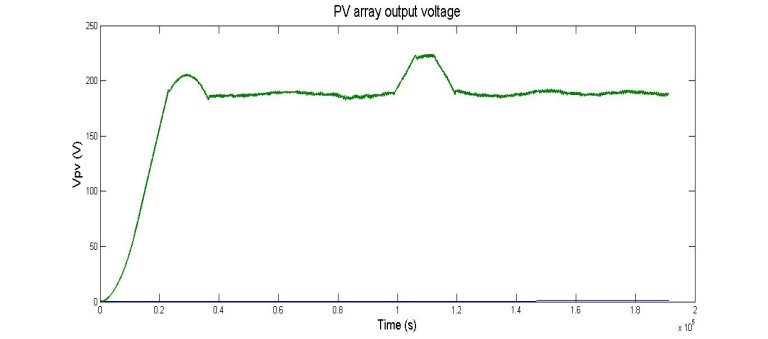 | Figure 11. PV array output voltage |
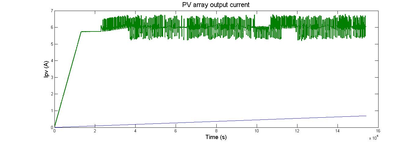 | Figure 12. PV array output current |
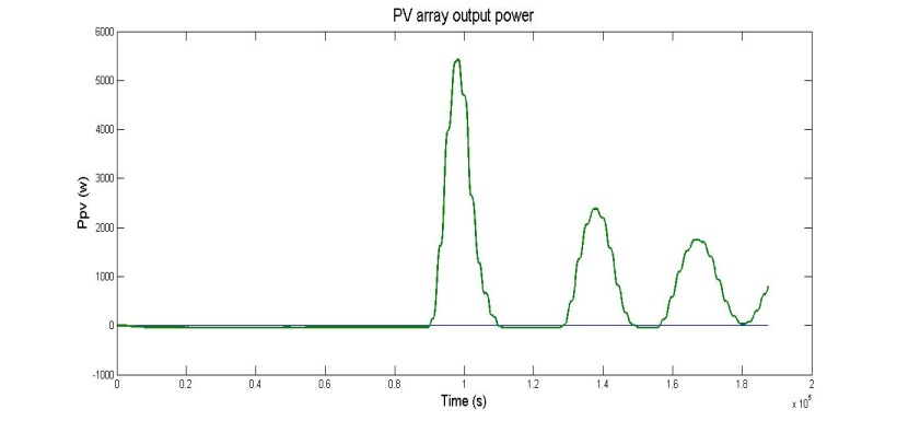 | Figure 13. PV array output power |
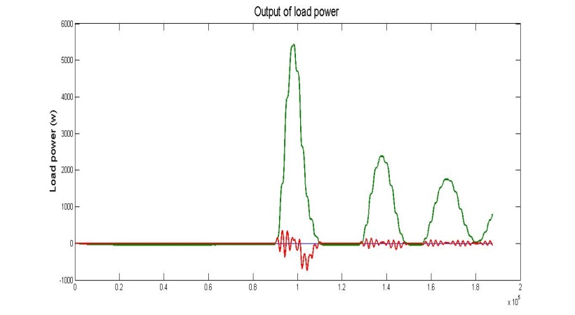 | Figure 14. Output of load power |
6. Conclusions
The Simulation of the above mentioned system is done in MATLAB software tool. Based on simulation result, it can be observed that DC power from PV array can be boosted and converted into sine wave AC output with very less harmonics distortion. The fundamental frequency of the AC output lies within 50HZ. The extracted power will be utilized by local loads and excess power will be feedback to grid.
ACKNOWLEDGEMENTS
I express my sincere gratitude to Mr. Pradeep Kumar, Assistant professor, Dept of E&E, for his cooperation and guidance. I extend my sincere thanks to our esteemed institution NMAM Institute of Technology, nitte Education Trust & VTU, Belgaum in carrying out the research work.
References
| [1] | S.B. kjaer, J, K. Pedersen, “A rewiew of single-phase grid connected inverters for photovoltaic module,” IEEE Trans.on Industry applications, sep-oct. 2005. |
| [2] | Yang chen & K.M. Smedley, “A cost effective single-stage inverter wit maximum power point tracking,” IEEE Trans.on power electronics, Sept. 2004. |
| [3] | M. Fortunato, A. Giustiniani, “Maximum power point tracking in a one cycle controlled single stage photovoltaic inverter,” IEEE Trans. on industrial electronics, July 2008. |
| [4] | Tsai-Fu Wu, Hung-shou Nien, “A single-phase inverter system for PV power injection & activepower filtering with nonlinear inductor consideration,” IEEE trans on industry applications, July-Aug. 2005. |
| [5] | A.K. Verma, B. singh and D.T. Shahani, “Grid interfaced solar photovoltaic power generating system with power quality improvement at ac mains,” in Proc. of IEEE third international conference on sustainable energy technologies, Sept. 2012. |
| [6] | Fangrui Liu, Shanxu Duan, Fei Liu, “A variable step size INC MPPT method for PV systems,” IEEE trans. on industrial electronics, July 2008. |

 Abstract
 Reference
 Full-Text PDF
 Full-text HTML