Nazhat S. Abdul-Razak, Hayder I. Hashim
Department of Software Engineering, Information Institute for Postgraduate Studies, University of Information Technology and Communications, Iraq
Correspondence to: Hayder I. Hashim, Department of Software Engineering, Information Institute for Postgraduate Studies, University of Information Technology and Communications, Iraq.
| Email: |  |
Copyright © 2017 Scientific & Academic Publishing. All Rights Reserved.
This work is licensed under the Creative Commons Attribution International License (CC BY).
http://creativecommons.org/licenses/by/4.0/

Abstract
Smart garage is one of modern technology that provide an appropriate environment with high level of welfare and security to protect cars from theft through electronic symptoms that cannot be opened only by the smart card and imprint car owner. The system will be implementation in three phases:- First, simulation of smart garage system is usually perform by using special software, such as (ISIS 7 Professional and Fritzing programs). Simulation is used before building the system in real-world, to reduce the chances of failure to meet specifications, to eliminate unexpected obstacles, to prevent under or over-utilization of resources, and to optimize system performance. Second, the implementation of the system as hardware in the beginning without the use of expert systems and through the implementation of the system found that there is no coordination of work among the electronic parts that have been programmed and linked with each other. Third, hardware implementation of the system by using an expert system with the presence or absence of fuzzy logic and through the implementation of the system by using the expert system with existence of fuzzy logic I found the accuracy and consistency in work among the electronic parts, but in the case of implementation of the system by using the expert system without using fuzzy logic found that there are some pieces no accuracy in execution there functions for example, garage casual for entering to the garage is inaccurate when open and close operations. And as a result we have built a system characterized by high protection against theft and difficulty of penetrating the system and tinker with sabotage from third parties and the system provides flexibility and ease of use and simplicity of its facades and guidance provided for new users.
Keywords:
Fuzzy Logic, Fuzzy Expert System, PIC Microcontroller, Arduino, Temperature Sensor, MQ-5 Gas Sensor, Fingerprint Sensor, Simulation
Cite this paper: Nazhat S. Abdul-Razak, Hayder I. Hashim, Design a Reliable Engineering System by Using Fuzzy Expert System, Electrical and Electronic Engineering, Vol. 7 No. 1, 2017, pp. 1-10. doi: 10.5923/j.eee.20170701.01.
1. Introduction
To deal with the increasing number of the population in developing countries, hence appear the need for a cars parking that provide high security and ease of use In addition to the aspect service provided by it. From here appear they need for smart garage system is now looking feasible to adopt more easily. Smart garage system is begin as a small digital parking to management a vehicles by using radio frequency identification (RFID) technology This digital vehicle management system will enhance the utilization of parking space and help user check the availability of the parking space remotely since the system is connected to the Internet. The project will be implemented in four stages. The first stage consists of embedding the code into a tag and assigning the same to a car. The second stage is reading the data from the RFID tag to the microcontroller. In the third stage, the data is uploaded from microcontroller to the Ethernet network. The final stage is to keep a track of vacancies of the parking spaces. And he concluded by making use of the Paramount’s RFID kit and Silicon labs’ C8051F120 microcontroller and AB4 Ethernet development board with this digital parking system, a car with authorized RFID tag can fast enter the parking lot without manually scanning the parking permit. This parking system will also help users view the availability of the parking space remotely. Therefore, this system helped user reduce the wasting time of search parking lot and also improve the parking lot utilization [1-3]. Microcontroller based Multi-Level automatic car parking system Thus we have chosen to build an idea about this fact to have a worry free transportation system by using IR card security system. We are using IR because it’s cheap, does not require manual inspection or optical scanning and its interrogators can be integrated with IT infrastructure (databases, etc), and he concluded automation facilities are still not available in many of our industries because of high initial cost. Although there are some limited industries having automatic control systems, in case of malfunctioning. To overcome all these problems, our engineers should have adequate theoretical as well as technical knowledge about all types of automatic control systems. To face the challenge of automation in the industrial field we need vast knowledge. In this project we worked with Microcontroller, IR transmitting and receiving system. To increase the knowledge about automation this project will be helpful to us [4]. A Reservation based vehicle parking reservation system to overcome the problem of unnecessary time consumption in finding parking spot in commercial parking areas. In this proposed system, we reserve the parking slot in shopping malls, theatres and offices by using short message service (SMS). User reserves the slot by sending a message to GSM modem placed at the parking end. GSM modem gives slot number and a password if the slots are available which is used to allow or deny access to the parking area at the entrance and exit. IR sensor is used for the indication of empty slot with a green LED. The main contribution is the system has more security. Thus users can just reserve the parking slots using the SMS.And he concluded the objectives of this project is the hassle in searching for available parking slots has been completely eliminated by reserving the slots beforehand via the SMS system and RFID System. These system helps users reduce the wasting time of search parking slot and also improve the parking slot utilization [5].
2. Experimental Part
2.1. Introduction
Building smart garage system will be perform in a sequential stages starting from simulation of system through using simulations programs (such as ISIS 7 Professional program, and Fritizing program), and after then it has been building the hardware parts such as fixing ground structure and ending with last special electronic part to build this system, finally execution and performance assessment to the system to check the operation and perform of the system.
2.2. Engineering Design
In this stage, the project was implemented step by step, where we started to work on the outer circumference of the project consisting of cork Alvrthur a thickness (3 cm)used in the models of buildings by engineers architecture where we used to install the sensors on its (such as lighting, LED, LCD, fingerprint sensor,.... etc) and also give appropriate shape to understand the purpose of this project by anyone to give him the best impression about the system, and from other hand it is important to also absorb the largest part of the idea of the project by looking before entering the precise details of the project and explain fully system in details and shown how each part of the system is worked in detail additional to clarifying the function of each part within the system.
2.3. Simulation of Smart Garage System
Simulation is the emulation of the system operations in a real-world or check system over time. And usually perform on a computer with appropriate software. Simulation enable perceive the interactions that would otherwise be apparent because of their separation in time or space. Simulation is used before an existing system is altered or a new system built, to reduce the chances of failure to meet specifications, to eliminate unforeseen bottlenecks, to prevent under or over-utilization of resources, and to optimize system performance. Simulation which applied to our system to work the simulation of all components of the system for checking the efficiency and reliability of the system as well as to make sure that all system components are working in a coordinated manner with each other and also trained to use the system and reduce the cost that is spent in the event of system damage and damage to one of the electronic components and thus be replaced so that the system returns to work from a new, addition to the many features that have been mentioned above, which can be used when making a simulation of the system by using the two programs and two (Fritzing software and ISIS 7 Professional software).In the smart garage system the information of user request must be checked in database of system to make sure this and there are two chooses:- first if request is correct (smart card is known & fingerprint of user is identical) then open casual, operation lighting and offer guidance to the user to help him in stop his car, and second if request is not correct then the system denial request. Figure 1. shown schematic of smart garage.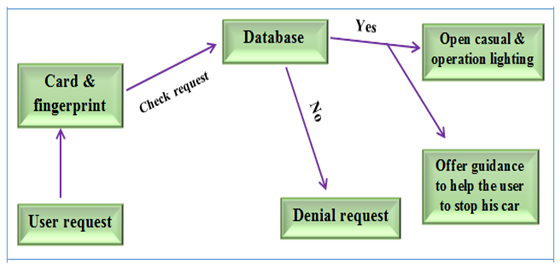 | Figure 1. Schematic of Smart Garage |
2.3.1. Simulation of Smart Garage System
It is necessary to translate model into computer recognizable format. The model of the system must be programming in a simulation language by using special simulation software such as:-ISIS 7 Professional, Fritzing. As shown in Figure 2. A & B.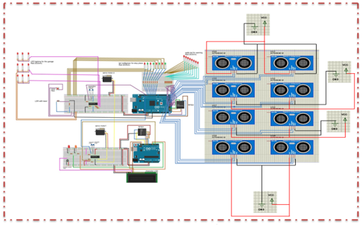 | Figure 2. A) Simulation of Smart Garage System by Using Fritzing |
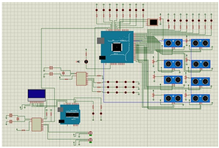 | Figure 2. B) Simulation of Smart Garage System by Using ISIS 7 Professional |
The main thing behind the system simulate is to running the model and trying to understand the results. A simulation is an experiment that needs to be designed and implementation of the system in reality to Identify purpose of the project or system.The goal of simulation experimental design is:-A) Find out quickly which factors are unimportant and forget about them.B) Build simple proxy models of complicated, expensive simulation models.C) Use simulation to optimize system performance.D) Use simulation to measure the effect of changes in factor levels.After then it has been perform verification and validation on the experimental design of the system that design by simulation programs. In verification process determining if the operational logic is correct to debugging the simulation software. And in validation process determining if the model accurately represents the system and comparison of model results with collected data from the real system that we build it. As shown in Figure 3.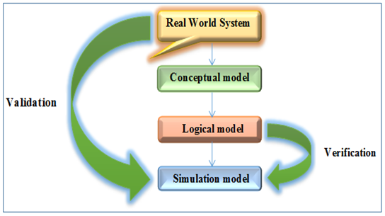 | Figure 3. Verification & Validation Process |
2.4. Design Smart Garage System
At this phase the system has been built in reality in several stages where they are testing and experimenting and checking system by users where the user using the system and submit his opinion on the system when it is used here are the opinion of the users who will be judged on the system with success or failure, and here judgment process on the system depends on the flexibility provided by the system addition to smoothness and ease of use of the system and also the reliability and accuracy of the system is based.
2.4.1. Ground Structure
Ground floor structure consists of cork Alvrthur White proportions (60cmX60cm) and also was installed walls consisting also of cork on the floor of the temple with a thickness (2 cm). In addition to installing roofs and reinforced from the inside to give it the stability of high and ensure that its downfall. Designed of the garage structure by using a program (3DMAX) and has printed and completing the desired shape in order to explain the bulk of the project by looking at him. Figure 4. shown ground structure of the system.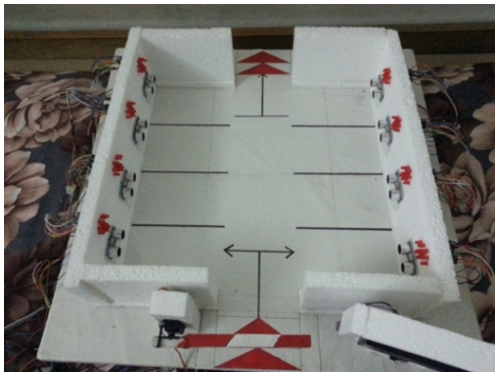 | Figure 4. Ground Structure |
2.4.2. Arduino UNO
Arduino UNO R3 is a microcontroller board based on the ATmega328P [6, 7]. It has been connecting several parts with it and controlling on its, and these electronic pieces that connecting with it is ((PIC Microcontroller) to control on the servo motor in open and closing garage casual, (LCD Screen) for display information, command and notes for users, (RFID1) to read smart card of users and after check it send signals to arduino and wait imprint of user for open garage casual in case card UID and imprint is identify open garage casual and in case card UID and imprint of user is unknown not open garage casual. also the work of RFID(1) is linked with fingerprint sensor They work together, (fingerprint sensor) used to scanning the finger of user and perform process of matching fingerprint this person with the fingerprints stored in the internal memory to check it if identifying or not after then send signal to arduino to check the information that sending from fingerprint sensor). As shown in Figure 5.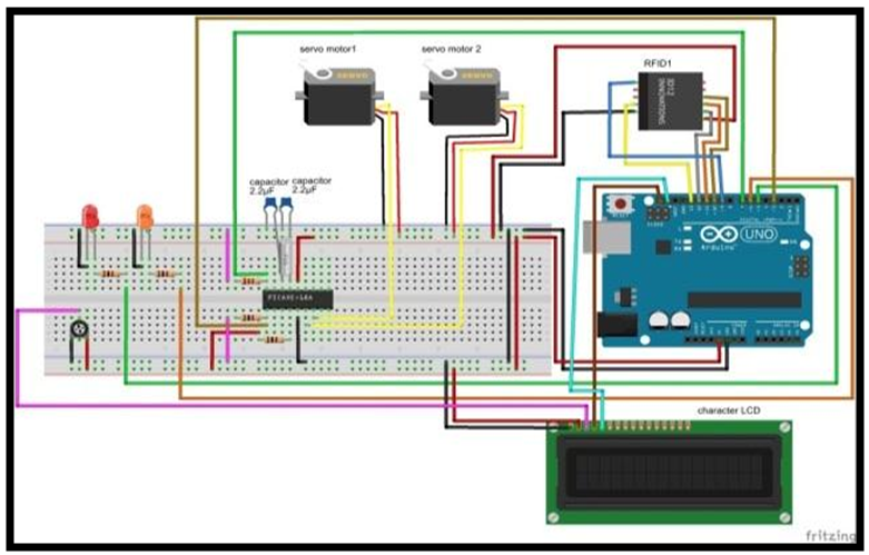 | Figure 5. Connection Diagram between Arduino UNO and Other Part in the System |
Arduino has made in control of all operations, including check the person's information and verification of the fingerprint person and after the verification of all the person's information and compliance with the system database and make sure it is correct then the Arduino sends signals are serialized parts associated with it and all of these parts fumbles transmitted signal him by Arduino and performs a specific function.
2.4.3. Arduino Mega 2560
The Arduino Mega 2560 is a microcontroller board based on the ATmega2560 [6, 8]. Arduino Mega 2560 is responsible for several functions including controlling on the ultrasonic sensors and LEDs stop in the ceiling and RFID which in turn is responsible for controlling the opening and closing casual exit of the garage, addition the Arduino Mega 2560 is sending signals to PIC Microcontroller, which in turn control of the smart lighting of the garage. As shown in Figure 6.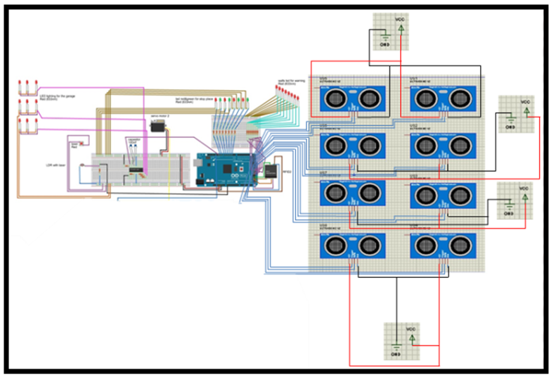 | Figure 6. Connection Diagram between Arduino Mega 2560 and Other Part in the System |
A) Ultrasonic sensorThe Ultrasonic Sensor HC-SR04 is one of the most commonly used for distance measuring, ultrasonic sensors works extremely well with Arduino. As shown in Figure 7.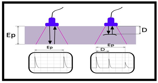 | Figure 7. Ultrasonic Waves |
Ultrasonic sensor contain sender ultrasonic waves where he sends ultrasound waves forward and when these waves hit the car will bounce back and receive by waves recipient ultrasonic waves and when the sensitive receives these waves, it calculates the time of the transmitter and colliding with the car and bounced back multiplied by the speed of sound to calculate the car distance from the wall of the garage, and when it becomes the distance of the car from the wall is (5 cm) the sensitive of ultrasound waves sends a signal to Arduino Mega 2560 and then the Arduino Mega 2560 send a prompt to run LEDs installed in the wall of the garage to alert the driver that he close to wall of the garage. Figure 8. shows ultrasonic sensor and LEDs wall.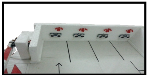 | Figure 8. Ultrasonic Sensor and LEDS Wall |
B) LEDs wallA light-emitting diode (LED) is a two-lead semiconductor light source. LEDs function as an alert driver of the car he close to wall of the garage the LEDs turn on and turn off after ultrasonic sensor sensitive that the car closed from the wall of the garage (5 cm), and this value is variable depending on what has been the ultrasonic sensor programmed and after the ultrasonic sensor is a sensitive the distance of the car is becoming (5 cm) from the wall of the garage sends a signal to Arduino Mega 2560 and Arduino sends a signal to the LED connected with this sensor where this LEDs work in the form of flashes alert the driver of approaching from wall of the garage. Show Figure 9. LEDs wall.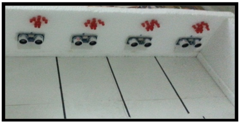 | Figure 9. LEDS Wall |
C) LEDs stop in the ceilingThis LEDs similar to the LEDs used to alert the car driver is approached from the wall of the garage, but the difference in the function performed in addition to this LEDs site be in the ceiling of the garage and its function is to facilitate to the driver of the car For knowledge the empty spaces in the garage to parking his personal car and therefore shorten the time that takes the driver of the car to find empty places to stop his car. Two colors of LEDs are used and these two colors are red, which indicates that this place is not available or there is a car parked in this place either the other color is a green color, which indicates that this place is empty or available to stop the car and this LEDs work after that the ultrasonic sensor Give stop signal to the driver by alert him using LEDs installed in the wall of the garage and at the same time ultrasonic sensor sends signal to the Arduino Mega 2560 to alert the system that this place became unavailable or reserved or was stopped car in it. Figure 10. shows the LEDs stop in the ceiling.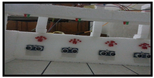 | Figure 10. LEDs Stop in the Ceiling |
D) PIC Micro controller 16F84aThis PIC Microcontroller difference form PIC Microcontroller connected with the Arduino Uno only in function of where this PIC Microcontroller to control the Smart Garage lighting. The principle of operation is after it is opened casual garage and then enter the car to a garage is cut light emitter from the laser and the laser wavelength is about LDR causing the passage of current flowing in this light resistance smoothly and thus Ardino Mega 2560 is sensitive this current through ports analog located in it, and then sends a signal to PIC Microcontroller and then the PIC Microcontroller run lighting own for the garage and this feature has been added for the purpose of reducing the power consumption and thus reduce the wages of the electric power consumption for this garage. Show Figure 11. Arduino mega 2560 with LDR, LEDs and laser connection. Figure 12. shows the LEDs installation, LDR and laser.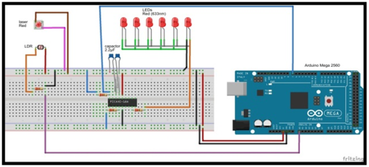 | Figure 11. Arduino Mega 2560 with LDR, LEDs and Laser Connection |
 | Figure 12. LEDs, LDR and Laser Installation |
E) RFID2 (Radio Frequency Identification)RFID (2) similar in function to the RFID (1) which was responsible for the entry of cars to a garage but the difference is that RFID (2) is responsible for door car out of the garage as well as the RFID (2) connected with Arduino Mega 2560. Figure 13. shows the connection diagram of RFID (2) and servo motor (2) with arduino mega 2560.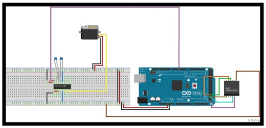 | Figure 13. Connection diagram of RFID (2) and servo motor (2) with arduino Mega 2560 |
2.4.4. Arduino UNO R3
Arduino uno in this part it is used to connecting and controlling on gas sensor (model MQ-5), LM35 IC temperature sensor and FAN. It is coordinates the work between gas sensor, temperature sensor and FAN in efficiently and accurately forms as shown in Figure 14.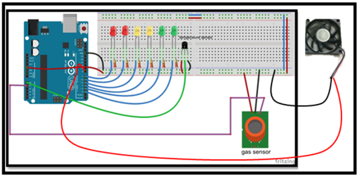 | Figure 14. connecting between arduino UNO & gas sensor & temperature sensor & FAN |
A) Gas sensor (MQ-5)In this electronic piece that connected with arduino is responsible for sense H2, LPG, CH4, CO2 gases emitted by leakages and as a consequence this sensor sense this gases and after then the sensor send signal to the arduino, after then arduino send signal to turn on FAN to reduce the percentage of gas inside the garage to keep people's lives from the danger of these gases. As shown in Figure 15.B) Temperature sensor (LM35)In this electronic piece that connected with arduino is responsible for sense temperature of the place, if the sensor sense the temperature is 1000 degrees Celsius or higher then temperature sensor send signals to arduino that connected with it, and arduino in turn send two signal, the first signal is to stop the operation of gas sensor to prevent this sensor from send signal to arduino to turn on the FAN, second signal to operation of fire extinguishing system using foam and special gases to extinguish the fire and turn on LEDs red for danger alert. And if temperature is less than 1000 degrees Celsius the sensor send signal to arduino and arduino in here turn send signal to turn on yellow LEDs to alert of the average danger. And if the temperature is less than 200 degrees Celsius the sensor send signal to arduino and arduino in here turn send signal to turn on green LEDs to alert from slight danger. As shown in Figure 15.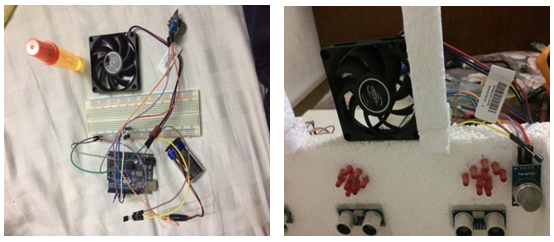 | Figure 15. Gas Sensor & temperature sensor |
2.5. Building a Fuzzy Expert System
The architecture of a fuzzy expert system showing the flow of data through the system is shown in Figure 16.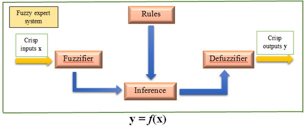 | Figure 16. Generic Architecture of a Fuzzy Expert System |
The general process of constructing such a fuzzy expert system from initial model design to system evaluation is shown in Figure 17.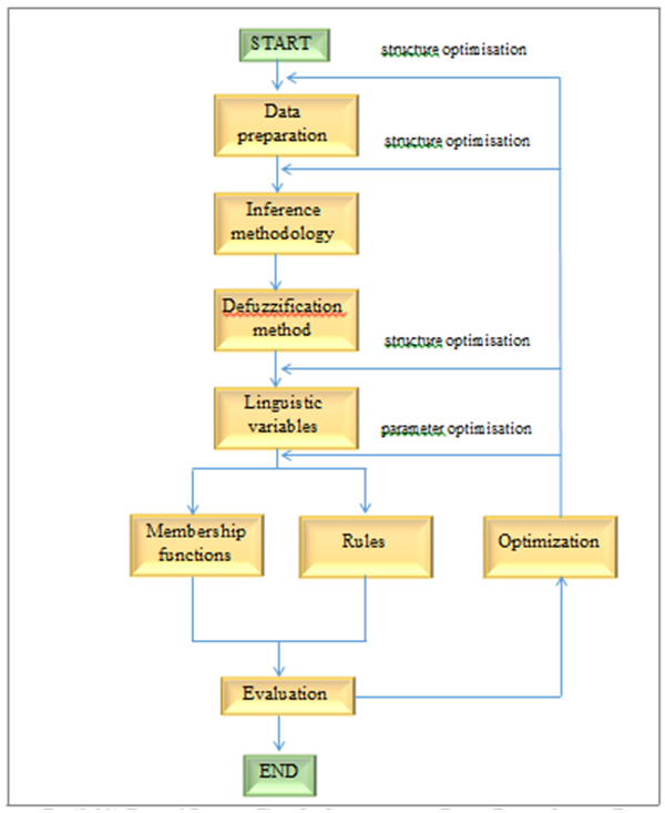 | Figure 17. Typical Process Flow in Constructing a Fuzzy Expert System for Smart Garage |
1) In the beginner to design a fuzzy expert system to the smart garage you must be define the problem clearly and in this system we faced three problems and They are explain as follows:-v Average waiting time (time_delay).v The system ability to repair errors (repair_error).v Maximum number of the car can be Borne by the garage (mcar_no).2) Data Preparation and PreprocessingData preparation and preprocessing is an essential and fundamental component of fuzzy expert system design. In the smart garage system we use three primary variables (sm_card, imprint and mcar_no) as input variables to the system. And we used difference information such as daily, weekly or monthly differences to keeping reports of errors that may occur when the wrong use of the system or at a certain defect occurs during the system works (the daily, weekly and monthly differences of repair_error) and produced three output variable advice, error message and open casual garage. Alternatively, it might be that all useful information was contained in daily differences so that only three input variables were used. Viewed this way, an optimization technique might be employed to carry out combinatorial optimization from a fixed choice of input variable combinations. Alternatively, the period (no. of days) over which the difference is calculated could be included as a tunable parameter within data preparation which could be carried out under control of a parameter optimization technique. 3) Inference MethodologyA) Mamdani InferenceIn this research we used this method for derivation rules that well be used in build the system (smart garage system). In Mamdani inference, rules are of the following form:Ri if x1 is Ai1 and. . .and xr is Air then y is CiFor i = 1, 2, . . . , LWhere L is the number of rules, xj (j = 1, 2, . . . , r) are the input variables, y is the output variable, and Aij and Ci are fuzzy sets that are characterized by membership functions Aij(xj) and Ci(y), respectively. The important thing to note is that the consequence of each rule is characterized by a fuzzy set Ci. When applying Mamdani inference on smart garage system for an illustrative eight-rule system. The final output of a Mamdani system is one or more arbitrarily complex fuzzy sets which needed to be defuzzified.IF fingerprint is identical and card UID is knowing and garage is not full Then casual garage is openIF fingerprint is identical and card UID is undefined and garage is not full Then casual garage is not open and error message is showIF fingerprint is not identical and card UID is knowing and garage is not full Then casual garage is not open and error message is showIF fingerprint is not identical or card UID is undefined and garage is not full Then casual garage is not open and error message is showIF fingerprint is identical and card UID is knowing and garage is full Then casual garage is not open IF fingerprint is not identical or card UID is undefined or garage is full Then casual garage is not open and error message is showIF fingerprint is not identical and card UID is knowing and garage is full Then casual garage is not open and error message is showIF fingerprint is identical and card UID is undefined and garage is full Then casual garage is not open and error message is show 4) Linguistic Variables and Membership FunctionsIn the smart garage system there are three primary variables (sm_card, imprint and mcar_no) as linguistic variables are used for interpretation. In the context of a fuzzy expert system, the source of membership functions would ideally be domain experts. However, again, there is no generally accepted method for eliciting membership functions from experts. It have been identified membership based on the experience of experts and based upon we design the decision-table. An excellent survey of methods for membership function elicitation and learning is given by Simon (1977) [9] that use decision-making process as shown in Table 18.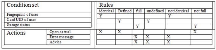 | Table 18. Fuzzy Decision-Making of Smart Garage System |
5) DefuzzificationThere are two principal classes of defuzzification, arithmetic defuzzification and linguistic approximation. We are used the method linguistic approximation because there is no needed to extract the single value that represents the ‘best’ value in the arbitrarily complex consequent fuzzy set, only we need to compared against the actual output set in a variety of combinations until the ‘best’ representation is obtained in natural language. In linguistic approximation a similarity measure is used to compute the distance between the actual output set and an arbitrary collection of primary terms, connectives and hedges. In the smart garage system we used three primary variables (sm_card, imprint and mcar_no) in my system produce a composite linguistic term such as sm_card and imprint to open casual garage after making sure of the input data. One such similarity metric is the Euclidean distance between fuzzy sets, given by: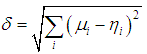 | (1) |
Where μi is the membership of the output set and ηi is the membership grade of the currently considered linguistic approximation the minimum value of δ will determine the best match. Alternatively, the degree of overlap, γ, of two fuzzy sets, A and B, can be calculated by dividing the area of intersection by the area of the union of the sets: | (2) |
To give a value between zero (for disparate sets) and one (for coincidental sets) the maximum value of γ will determine the best match. After then search is initiated to find the best match whilst attempting to limit the complexity of the combination of terms, in order to produce comprehensible output.6) EvaluationThere are many terms used to evaluation expert system (verification, validation, Credibility, assessment and evaluation). The validation test has been used in this research. We found after using the validation test, that the validation is the process of ensuring that the knowledge embedded within the expert system is an accurate representation of the domain. The purpose of this test is to ensure the efficiency and effectiveness of the system and its responsiveness to the instructions that generated by users of the smart garage system and speed of implementation as quickly as possible based on the knowledge base that existing within the fuzzy expert system.Usually we need to validate the model to measure the generality of the model. Since a model is never absolutely valid its acceptance is very dependent upon the intended use and user. For this reason model builders have started to focus more on credibility. And the model would be more credible, but there is no guarantee that a valid model will be perceived as credible.7) Model OptimizationOptimization is an essential part of developing any fuzzy expert system. It may be used to adapt a fuzzy expert system in a certain domain to changes in the environment. Effectively, it can be viewed as the process of adapting an fuzzy expert system to the specific characteristics of the training and testing data available at the time. Thus the optimization process could be applied at several stages in the lifetime of an fuzzy expert system in order to update the knowledge embedded in the fuzzy expert system. The most significant influences on the performance of an fuzzy expert system are likely to be the number and location of the membership functions and the number and form of the rules. There is no general result to state that any one optimization technique is guaranteed to be better than any other. This does not necessarily apply to any given subset of optimization problems (e.g. specifically to optimization of fuzzy models). The construction of a successful fuzzy expert system is a difficult process that requires considerable expertise from engineer in domain fuzzy knowledge. It is probably the large number of design choices and tunable parameters of the resultant expert system that are partly responsible for the success of fuzzy expert systems for smart garage. Fuzzy expert system have been designed which will automatically adapt itself somehow to the environment it faced.
2.6. Execution and Performance Assessment
The implementation of the system and applied and tested in reality and tested myself inside my personal garage by used my personal car and apply all the commands required for entry into the garage (the use of smart card and fingerprint) as a user who the will using the system and all electronic parts installing inside Read the garage and run entirely through my use of the system and found the ease of handling and high flexibility and speed of implementation, additional the instructions that provided to the user when they do not know how to using the system correctly or the user used the system for the first time.The implementation of the smart garage system by using fuzzy expert system in three stages:-Firstly, the implementation of the system by using simulation software on computer for the purpose of the facility and to identify the mistakes or errors very easily in addition to test and check the work of all electronic parts by simulation programs before piloted in reality and these programs are ISIS 7 professional and fritizing for simulation.Secondly, the implementation of the system as hardware in the beginning without the use of expert systems with presence or absence of fuzzy logic and through the implementation of the system and found that there is no coordination of work among the electronic parts that have been programmed and linked with each other.Thirdly, the implementation of the system by using an expert system with the presence or absence of fuzzy logic and through the implementation of the system by using the expert system with existence of fuzzy logic and through him I found the accuracy and consistency in work among the electronic parts, but in the case of implementation of the system by using the expert system without using fuzzy logic found that there are some pieces for example, garage casual for entering to the garage is inaccurate when open and close operations and smart lighting for garage is not accurate.
3. Result & Discussion
The system has been implemented in three phases as explained above and during each phase of the entire system has been tested and watch the results or outcomes after the implementation of the system below:-First: Hardware Implementation At the beginning the system implemented as hardware only without use of fuzzy expert system and through the implementation of the system it has been found that there is no coordination of work among the electronic parts that have been programmed and linked with each other, where it is through the operation of the system without the presence of an expert system noticed that electronic parts do not work in a coordinated manner with each other and all the pieces was programmed according to their function and place that put in and found that it does not doing the implementation and function correctly or as it is required to accomplish. The reason is the lack of knowledge base that system built upon. When implementing my system for example servo motor does not open the garage casual accurately additional to that lighting ceiling that work when sensitive entry of cars but also it does not work correctly. Figure 19. shown the implementation of the system without using expert system.a) In this picture LEDs celling and places LEDs (places LEDs used to indicate that a place is reserved or there is a car that parked in this place) does not work correctly according to what has been programmed it.b) In this picture it has been used smart card and fingerprint to open garage casual to allowed the cars to entry to the garage and garage casual is moved by servo motor and this motor is not been work correctly.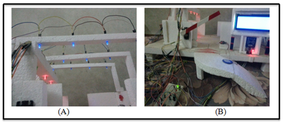 | Figure 19. Implementation of the System without Using Expert System (A, B) |
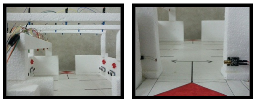
Second: The implementation of expert systemThe implementation of the system by using an expert system, through the implementation process of the system it has been found that there are some pieces for example, garage casual for entering to the garage is inaccurate when open and close operations. But there is some smart in some electronic parts, for example, ultrasonic sensor and LEDs ceiling for alarm which refers to the place where the vehicle stops is reserved or not, additional to that casual that responsible for the entry and exit of cars needed to vary high accuracy in the degrees of opening and closing the casual, but there are not getting all them with using the system expert only. The reason goes back to that voltage value on which servo motor runs it variable and not fixed, thus servo motor needs a high accuracy in handling and calculate the opening and closing angles and for this reason the use of an expert system only inadequate, because we need to calculate the angle of the casual accurately. In addition to that ultrasonic sensors also need to calculate the impacting waves with body car and waves feedback to a recipient in the same sensitive ultrasonic and then send a signal to arduino, the arduino in turn sends a signal to the LEDs ceiling responsible for alerting that place is reserved or not. Figure 20. shown implementation of the system with using expert system.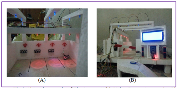 | Figure 20. Implementation of the System with Using Expert System (A, B) |
a) In this picture operation of system and check LEDs ceiling, places LEDs & ultrasonic sensors to check it work correctly or not.b) In this picture operation of system and check garage casual and accuracy of servo motor and it synchronize with PIC depending on the signals that send from arduino.Third: The implementation of fuzzy expert system By using fuzzy expert system can be achieved several goals such as high accuracy in executed instructions and coordination between electronic pieces because fuzzy logic works here in the analysis of decimal values (non-real) and makes them intelligible in machine language and making electronic pieces able to distinguish these numerical values which are usually not understood in machine language because machine language is only able to distinguish values (0 or 1), here we needed to have a fuzzy logic to transform these decimal (non-real) values into values that could be understood by electronic pieces and the implementation of instruction is very careful for example garage casual that responsible for entered and exit for the garage become more accurate in opening the bar and stopped at a 90 degree angle to enter cars that registered to enter the garage and close the bar and stopped at 0 degree angle, this prevent the entry of undesirable cars from entered. And also the ultrasonic sensors operated on various voltages (between 3.3V minimum & 5V maximum) and which is helped to alert the driver of the car is near to the wall by sending a signal to arduino and from arduino to LEDs linked and programmed with arduino and waiting for the signal in order to operate in it turn to alert the driver through operate and extinguish LEDs wall and LEDs ceiling which indicates that the place reserved or empty. All this depends on the accuracy of ultrasonic sensors and the extent of its speed and accuracy in the measurement of the distance and the major factor depends on the voltage supplied from the source. In order to maintain the accuracy of the system it must be work with voltage (3.3V) and this has been obtained through the use of fuzzy logic with the expert system and benefit from the knowledge base of the system that built upon. In additional LEDs ceiling of the garage which are associated with the laser are emitting light (LDR) that passes the package in a straight line and there from the opposite side photoresistor being an electric current through them and these photoresistor sensitive to laser light, thus hinder the current flow through it easily, when the car is entering cutting laser light this cause the passage of power easily without any resistance. As a result the operation of lighting the garage is done but current flow through the photoresistor is calculated in the form of values, these values very depending on the voltage that system is working on it, also to measure these values accurately we used fuzzy logic to approximate the real values to decimal values can be handled quite easily and also we must work into account that the photoresistor affected with the normal light, any normal lighting as well as daylight and values (values that may be obtained as a result Light resistance inside of photoresistor) must be calculated for each of them and the ignoring these values and focus only on the light which is emitting from laser only, thus it has been built a system characterized by high protection against theft and difficulty of penetrating the system and tinker with and sabotage from third parties and provides flexibility, ease of use, simplicity of its facades and guidance provided for new users. The system provided high security to protect cars from theft by using of smart card and fingerprint and do not be allowed unwanted cars to enter to the garage. Also the system provided ease with high flexibility to the users. Figure 21. implementation of the garage system with expert system by using fuzzy logic (A, B, C, D, E).a) In this picture operated all parts of the system.b) In this picture it has been used (smart card & fingerprint) of user to permitting to enter to the garage or not.c) In this picture after read ID of smart card and fingerprint of user and check it identify to the system, as a result open garage causal this permit car to enter to the garaged) In this picture after car enter to garage the driver of car select blank place depending on celling LEDs when he found led green operated the place is blank, or when found he led red operated the place is reserved.e) This picture represented the overall implemented of smart garage system by using fuzzy expert system. 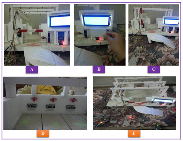 | Figure 21. Implementation of the garage system with expert system by using fuzzy logic (A, B, C, D, E) |
4. Conclusions
The conclusions of the present work are:-1. Smart garage using an expert system with a fuzzy logic providing high security to save personal cars from stolen or tampered with those persons who are unwelcome, and using fuzzy logic increased the accuracy and efficiency of the system.2. When implementing the system just as Hardware it has been found a weakness of consistency and accuracy in work among the electronic parts and the reason is due to the lack of knowledge base can system return to it when performing operations and thus we are lost the most important characteristics that must be met in the system which is considered a measure of the success of the system, and these characteristics are verified and validation and credibility and efficiency.3. Using an fuzzy expert system for implementing the garage provides an important advantage according to knowledge base used by the expert system that system built upon which implemented the special operations of the system.4. Using the devices (fingerprint sensor, gas sensor, PIC microcontroller and LMR sensor, RFID) increased the accuracy, constancy, security and efficiency of the system. 5. Simulation process of the system facilitated operation of building the garage and helped in discovery of errors on early. Also the simulation environment tested in terms of accuracy in the work, the speed of response, ease of use, efficiently of the system and reduces the costs that may be occur as a result to be lose same electronic pieces, the reason back to Instability of current voltage or errors in connecting electronic parts the work of system.
References
| [1] | Milan Verle, “PIC Microcontrollers - Programming in C”, micro Elektronika, 1st Edition, 2009. |
| [2] | Dogan Ibrahim, "Advanced PIC Microcontroller Projects in C: from USB to RTOS with the PIC18F series", 2008. |
| [3] | Uma Kanth Ranga, Xiaolong Li, "Design and Implementation of a Digital Parking Lot Management System", Technology Interface Journal, Vol. 10, No. 1, 2009. |
| [4] | Kamrul Hassan, Md. Mustafizur Rahman, Fatema-Tuz-Zohra, Mohammad Sakib Hossain, R.M.M. Hasan, "Multi-Level Automatic Car Parking With IR Card Security System", International Journal of Scientific & Engineering Research, Vol. 3, Issue 12, December-2012. |
| [5] | K. Sushma, P. Raveendra Babu, J. Nageshwara Reddy, "Reservation Based Vehicle Parking System Using GSM and RFID Technology", Int. Journal of Engineering Research and Applications, Vol. 3, pp.495-498, Sep-Oct 2013. |
| [6] | http://0x9.me/ML7FA. Datasheet_11/2015. |
| [7] | https://www.arduino.cc/en/main/arduinoBoardUno. |
| [8] | https://www.arduino.cc/en/Main/arduinoBoardMega2560. |
| [9] | Jie Lu. Guangquan Zhang, Da Ruan, Fengjie Wu" Multi-Objective Group Decision Making", Vol. 6, 2007, p.5-9. |

 Abstract
 Reference
 Full-Text PDF
 Full-text HTML