-
Paper Information
- Previous Paper
- Paper Submission
-
Journal Information
- About This Journal
- Editorial Board
- Current Issue
- Archive
- Author Guidelines
- Contact Us
Electrical and Electronic Engineering
p-ISSN: 2162-9455 e-ISSN: 2162-8459
2016; 6(4): 68-73
doi:10.5923/j.eee.20160604.03

A Compact Ultra-Wideband Antenna with Time Domain Analysis
 Abstract
 Reference
 Full-Text PDF
 Full-text HTML
Umair Rahim, Baskaran Kasi
Department of Electrical and Electronics Engineering Infrastructure University Kuala Lumpur, Kajang, Malaysia
Correspondence to: Umair Rahim, Department of Electrical and Electronics Engineering Infrastructure University Kuala Lumpur, Kajang, Malaysia.
| Email: |  |
Copyright © 2016 Scientific & Academic Publishing. All Rights Reserved.
This work is licensed under the Creative Commons Attribution International License (CC BY).
http://creativecommons.org/licenses/by/4.0/

The Ultra-Wideband (UWB) communication systems has emerged as a technology that offers a great promise to fulfil the growing demands for short-ranged, high-speed wireless communications. Hence, this paper proposes the use of a compact patch bevel shaped microstrip ultra-wideband antenna design which has the capability to operate between a 3.1 GHz to a 10.6 GHz frequency range. An in depth investigation is conducted on the proposed antenna type whereby the partial ground plane and radiating patch, with parameters in frequency domain and field radiation patterns is examined. Apart from that, the measured S11 features that display the aptitude of an antenna as effective radiating elements, along with time domain analysis are also probed into. As a concluding outcome, the simulation results demonstrated a judicious agreement with the measurement results, signalling a good ultra-wideband linear transmission performance being achieved in the time domain.
Keywords: Ultra-wide band (UWB), FR4, Microstrip, Patch antenna, Frequency domain, Time domain
Cite this paper: Umair Rahim, Baskaran Kasi, A Compact Ultra-Wideband Antenna with Time Domain Analysis, Electrical and Electronic Engineering, Vol. 6 No. 4, 2016, pp. 68-73. doi: 10.5923/j.eee.20160604.03.
Article Outline
1. Introduction
- An antenna is defined as electrical device which converts electric energy into radio waves, and vice versa. Which is very useful with a radio transmitter or radio receiver. The antenna becomes an important part of electrical devices in wireless communication system in the late1888; Heinrich Hertz (1857-1894) were first who explained the radio waves [1].The Ultra-wideband (UWB) communication systems has emerged as a technology that offers great promise to fulfil the growing demand for short-range high-speed wireless communications [2]. Since the release of the UWB frequencies by the Federal Communication Commission (FCC) [3] ranging from 3.1GHz to 10.6GHz in 2002, UWB communications systems have received much attention to develop UWB antennas for emerging applications. UWB has promised to offer higher data rates, saturation of the frequency spectrum, low power and wide bandwidth are some of the reasons that increased the interest in the UWB during the past few years [4-7]. UWB, in comparison with narrowband systems, the antennas have greater impact in UWB system because of the optimized antennas due to its extremely wide bandwidth, the antennas transmit pulsed signals not continuous wave signals. Standard parameters in the frequency domain such as return loss, gain, radiation efficiency, etc. have been defined for narrowband antennas. Therefore analyzing UWB antennas only in the frequency domain is not enough as pulse distortion is an important parameter that should be controlled. Thus it is required to study the antenna characteristics in the time domain as well [8].In this paper, a simple and compact bevel shaped microstrip ultra-wideband antenna for UWB application is proposed. For bandwidth enhancement four different techniques are used such as partial ground, partial radiator and beveling technique on both ground and radiating patch. The return loss –10 dB bandwidth of the antenna covers 2.8 to 11 GHz which satisfies the UWB system requirement. The outline of this paper is as follow. Section 2 describes the proposed antenna geometry and configuration. Simulation and simulated results are presented in Section 3 and the conclusions are summarized in Section 4.
2. Antenna Design and Configuration
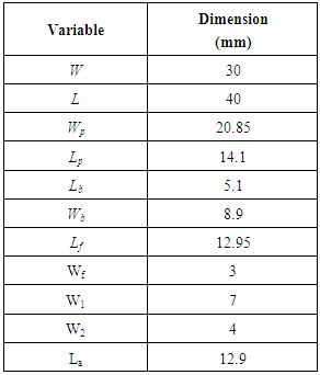
- The proposed compact UWB antenna configuration and its geometrical parameters are shown in Figure 1 and table 1 respectively. This proposed antenna design consists of partial radiating patch fed by a microstrip line printed on a partial ground and FR4 substrate with a total area of 40mm×30mm, thickness of 1.6 mm, permittivity of 4.4. The microstrip feed line is designed to match a 50 Ω characteristic impedance.
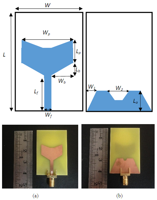 | Figure 1. Geometry and prototype of the proposed antenna (a) front view (b) back view |
|
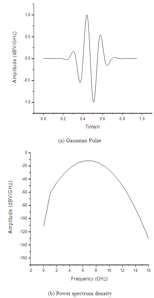 | Figure 2. Excitation signal in time domain and power spectrum density |
3. Results and Discussion
- The simulated and the measured return loss S11 of the proposed antenna is shown in Figure 3.
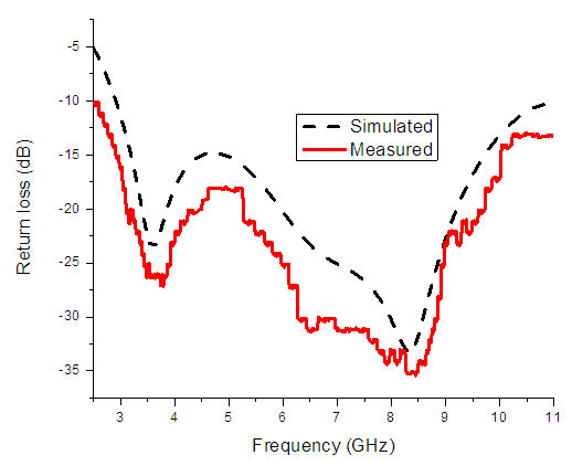 | Figure 3. Simulated and measured return loss of the proposed antenna |
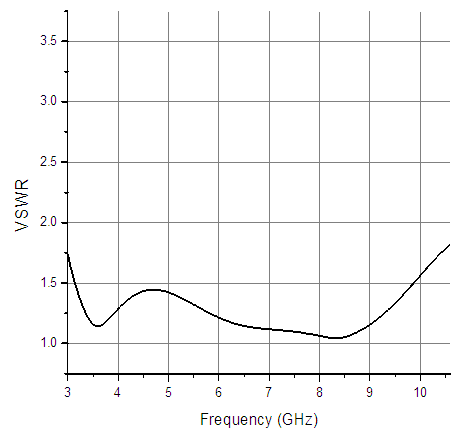 | Figure 4. Simulated VSWR of the proposed antennas |
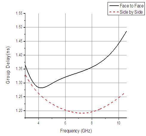 | Figure 5. Group delay of proposed antenna |
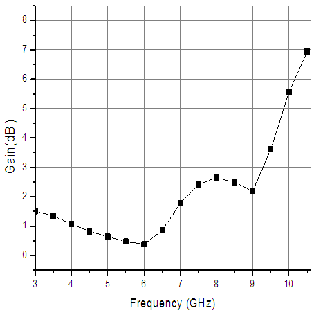 | Figure 6. Simulated gain of the proposed antenna |
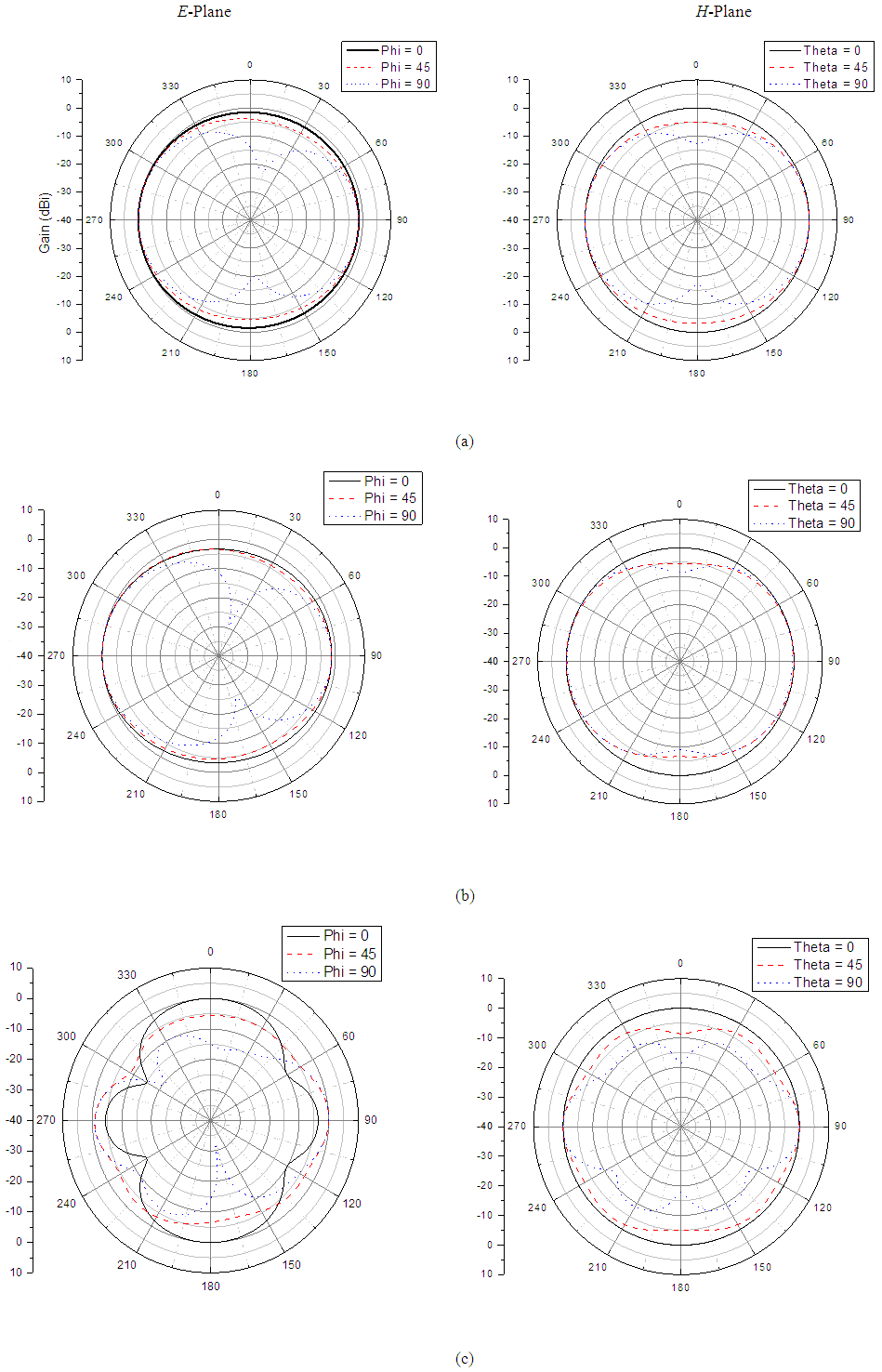 | Figure 7. Simulated E-plane and H-plane radiation pattern at (a) 3.5 GHz (b) 6.5 GHz (c) 10.5 GHz |
4. Time Domain Analysis
- In order to measure the antenna efficiency in time domain analysis, the pulse base signal is excited with the Gaussian pulse. Figure 8 shows the radiated E field which is virtually place probe in simulation to study the effect of radiated signal. From this figure the antenna is fixed at azimuth angle ϕ of 90, and the probe is placed at four different positions for θ of 0°, 30°, 60° and 90°. The results shows that the proposed antenna has good potential in transmitting UWB signals with minimum distortion.
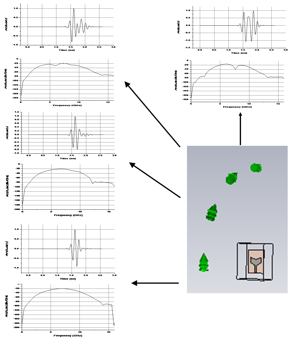 | Figure 8. Signal seen by virtual probe and respective power spectra density |
5. Conclusions
- This paper starts from a compact patch bevel shape microstrip ultra-wideband antenna for UWB applications. Frequency domain and time domain analysis has been carried out for proposed antenna. Total size of the antenna is equal to 40mm×30mm and have the ability to achieving an input impedance bandwidth from 2.8 to 11 GHz. The measured results of the proposed antenna fulfil the -10 dB return-loss requirement for UWB as defined by the FCC from 3.1 to 10.6 GHz. In addition, the antenna provides omnidirectional radiation pattern in both E-planes and H-planes. Finally, the proposed antenna can be considered as a strong candidate for cost effective UWB applications due to its very wide bandwidth.