-
Paper Information
- Next Paper
- Previous Paper
- Paper Submission
-
Journal Information
- About This Journal
- Editorial Board
- Current Issue
- Archive
- Author Guidelines
- Contact Us
Electrical and Electronic Engineering
p-ISSN: 2162-9455 e-ISSN: 2162-8459
2016; 6(4): 62-67
doi:10.5923/j.eee.20160604.02

Simulation of 12 Pulse DSTATCOM for Voltage Sag Mitigation
 Abstract
 Reference
 Full-Text PDF
 Full-text HTML
S. Salimin, A. Mohamad Shukri
Faculty of Electrical and Electronic Engineering, Universiti Tun Hussein Onn Malaysia, Malaysia
Correspondence to: S. Salimin, Faculty of Electrical and Electronic Engineering, Universiti Tun Hussein Onn Malaysia, Malaysia.
| Email: |  |
Copyright © 2016 Scientific & Academic Publishing. All Rights Reserved.
This work is licensed under the Creative Commons Attribution International License (CC BY).
http://creativecommons.org/licenses/by/4.0/

With the ongoing growth of technologies, maintaining the stability and reliability of power distribution to the load is vital. In this paper, a distribution STATCOM (D-STATCOM) is applied to help in the better utilization of a network operation under normal and voltage sag condition. The technique is propose by using PSCAD/EMTDC software. The study of the operation and control, including phase control technique had been carried out. Design and simulation of a 12-pulse D-STATCOM is done and analyzed where it shows the effectiveness of 12-pulse D-STATCOM in controlling and mitigating voltage sags occurring in distribution system line.
Keywords: 12 pulse D-STATCOM, Voltage sag, Distribution line, PSCAD
Cite this paper: S. Salimin, A. Mohamad Shukri, Simulation of 12 Pulse DSTATCOM for Voltage Sag Mitigation, Electrical and Electronic Engineering, Vol. 6 No. 4, 2016, pp. 62-67. doi: 10.5923/j.eee.20160604.02.
Article Outline
1. Introduction
- Flexible AC transmission systems, so-called FACTS devices, has been known to reduce power flow on overloaded lines [1]. In order to find the best location to install these devices, a graphical user interface (GUI) based on a genetic algorithm (GA) is normally used which able to find the optimal locations and sizing parameters of multi-type FACTS devices in large power systems [2]. FACTS devices can be shunt connected and series connected where the common devices implemented are Static Var Compensators (SVCs), Distribution Static Synchronous Compensators (DSTATCOMs), Static Synchronous Series Compensators (SSSCs), Thyristor Controlled Series Compensators (TCSCs), and the Unified Power Flow Controllers (UPFCs). For certain application, two or three FACTS devices may be in operation in one time in order to increase power transfer capacity, power system reliability, and power system controllability [3]. Shunt devices are normally connected at the receiving end of the power system network [4]. For the purpose of this project, 12 pulse DSTATCOM is applied to mitigate voltage sags occurred in distribution line, thus improve the power transfer capability. DSTATCOM generate and absorb reactive power at a faster rate because no moving part are involve plus it goes on well with advances energy storage facilities, which opens opportunities for other applications like energy market and security [5]. There are several papers that have been published mentioned on the effectiveness of D-STATCOM to improve power quality especially voltage sags [5-9].
2. Literature Review
2.1. Review on Power Quality Issues
- Ideally, electrical power supply should transfer a perfect sinusoidal voltage waveform to consumers. However, this is hard to achieve because of some reasons. Connection of non- linear loads and power electronics components are the most important reason for this problem to happen. In general, these two reasons may lead to power quality problems. Two vital problems are unwanted harmonics injection and voltage sags. In the past, harmonics was less of a problem but now, with the increasing use of non-linear loads, harmonic distortion in the distribution networks are on the rise [10]. Reference [11-15] are some of the methods proposed to reduce these harmonic distortions which results to improvement in power quality transfer. This paper concerns on another power quality issue that is voltage sags. Voltage sags occurs when there are short duration reductions in the voltage cause by faults in the supply system or during starting of large loads [16]. Voltage sags are commonly occur which can affect power quality. Reference [17] stated that, ‘a sag is a decrease in rms voltage to between 0.1 pu to 0.9 pu for durations from 0.5 cycles to 1 min’. To overcome sags problem, shunt and series device are normally applied to the system. This paper is therefore to enhance the 6 pulse DSTATCOM technique and simulate the 12 pulse DSTATCOM using PSCad. Then, analysis is done to the output before and after its application during fault.
2.2. Review on DSTATCOM
- A distribution STATCOM or DSTATCOM is a voltage source inverter coupled with a transformer and connected to the network as shown in Figure 1 [18]. The purpose is to inject a near to perfect sinusoidal current at the point of connection. The voltage source inverter converts an input dc voltage into a three phase output voltage at fundamental frequency. These voltages are controlled in phase and coupled with ac system through reactance of the coupling transformer.
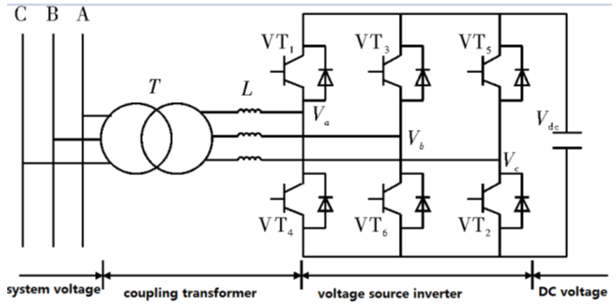 | Figure 1. Basic structure of STATCOM [18] |
3. Methodology
- A distribution line had a line-to-line voltage, 11kV is assumed load with IMVA at 0.9 power factor lagging had been design. The voltage source will act as secondary part of the transformer and is directly connected to the three-phase wye-connected load. The calculation for load impedances are done by considering only one phase. Therefore, using the values given earlier, the value for load resistance is 36.3 Ω whilst the value for load inductance is 0.05596 H. For this research, two 6 pulse DSTATCOM connected in parallel are used. The power switches are of gate turn-off thyristor (GTO) because of its capability to turn off and turn on by applying a positive gate signal. In order to maintain so that the load voltage is kept 1 p.u., PI controller is used to control the GTO. Besides that, PWM switching method is also applied to generate a three phase 50 Hz sinusoidal voltage. Figure 2 shows the test system with fault model in PSCad before the application of 12-pulse DSTATCOM.
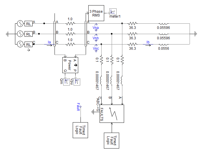 | Figure 2. Simulation System with Fault without 12 pulse DSTATCOM |
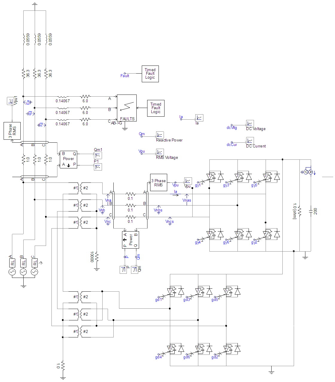 | Figure 3. Simulation System with Fault with 12 pulse DSTATCOM |
4. Results and Discussions
4.1. Simulation with Fault without DSTATCOM
- The distribution system that included the three phase balanced faulted was simulated for two second. The voltage sag had occurred at time 1.5 sec for duration 0.6 sec. Real and reactive power meter is used to measure the real and reactive power in the distribution line system. The reactive powers are important part for STATCOM because it will generate the reactive power to mitigate the voltage sag that was occurred. In this system, an 11kV, 50 Hz and 15MVA AC source and 1MVA load with 0.9 lagging power factor for each single phase are used.
4.1.1. Simulation Results of Single Phase to Ground Fault
- During fault at single phase in damage to land, it is categorized as a single line to ground. Single line to ground is one of the most common damage to the three-phase system. Based on the test systems, single fault line is assumed that the phase which has touched the ground since the system could not be loaded before damage was applied.The percentage of voltage sag condition occurs and disturbs three phase balanced fault occurs at distribution line system. Illustrated diagram as in figure 4 shows the Vrms voltage had decreased from 0.959 to 0672 per unit. This means that the total losses in the input voltage has an A phase to ground as many as 30% of the total losses in the input voltage has an A phase to ground. Changing the fault impedance can change the depth of the sag.
 | Figure 4. Simulation result of Single Phase to Ground fault without STATCOM |
4.1.2. Simulation Results of Three Phase to Ground Fault
- Next, three phase fault is created. Result in figure 5 shows the voltage sag occurs and disturbs the system. This time, the Vrms voltage had decreased from 0.959 to 0.052 per unit. This means that the total losses in the input voltage has an ABC phase to ground as many as 94.6% of the total losses in the input voltage has an ABC phase to ground.
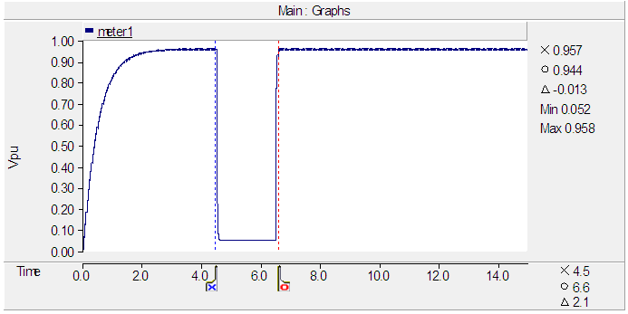 | Figure 5. Simulation result of three phase fault without STATCOM |
4.2. Simulation with Fault with STATCOM
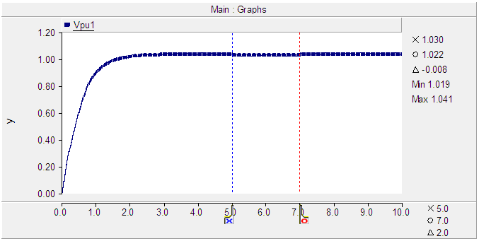
4.2.1. Simulation Result of Single Phase to Ground Fault with 12-Pulse DSTATCOM
- Next, a 12 pulse DSTATCOM is applied by connecting two 6 pulse DSTATCOM in parallel to the network. When the test model with single phase to ground is simulated, result of the system output voltage is as in figure 6.
 | Figure 6. Simulation with Fault with 12-PulseSTATCOM Single Phase to Ground |
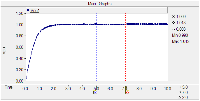
4.2.2. Simulation Result of Three Phase to Ground Fault with 12-Pulse DSTATCOM
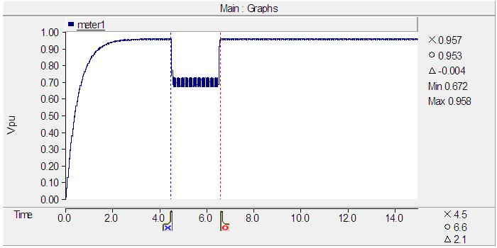
- With the connection of 12 pulse DSTATCOM, almost the same result is observed when the three phase fault occurred. This can be seen in figure 7. It shows the sag before has been totally mitigated and the Vrms output voltage is maintained 1 p.u. If the graph shows a spike at the beginning and at the end of the sag are due to the capacitor charging and discharging.
 | Figure 7. Simulation with three phase fault with 12-Pulse STATCOM |
5. Conclusions
- The implication of this study is that the generation of 12 pulse DSTATCOM in PSCAD is shown and results show the improvement in voltage performance after 12 pulse DSTATCOM is applied. From the result obtained, the 12-pulse DSTATCOM manage to mitigate and compensate the voltage sag of single line to ground fault and three phase fault without any difficulty. The performance of the power system with FACTS devices installed in it is better compared to the performance of the power system without the devices installed in it. The power quality problem cannot be eliminated wholly, but it can be reduced causing the consequences of this problem to be minimize as much as possible.
ACKNOWLEDGEMENTS
- The authors are grateful to Universiti Tun Hussein Onn Malaysia for supporting the expenses to this conference.