Siti Amely Jumaat, Firdaus Mohamad, Shamsul Aizam Zulkifli
Faculty of Electrical and Electronic Engineering, Universiti Tun Hussein Onn Malaysia, Malaysia
Correspondence to: Siti Amely Jumaat, Faculty of Electrical and Electronic Engineering, Universiti Tun Hussein Onn Malaysia, Malaysia.
| Email: |  |
Copyright © 2016 Scientific & Academic Publishing. All Rights Reserved.
This work is licensed under the Creative Commons Attribution International License (CC BY).
http://creativecommons.org/licenses/by/4.0/

Abstract
This project aims to develop a Portable Case Solar Battery Charger that can be carried anywhere for the use of electronic and electrical devices. In the Portable Case Solar Battery Charger there are two main systems that play a major role which is battery charger circuit and battery voltage level indicator circuit. The function Battery charger circuit is to control the output voltage of the solar panel by using a variable resistor in the circuit. Meanwhile, the battery voltage level indicator circuit is used to monitor the voltage level of the battery by using the LED display. The output of this project is produced two types of output, which is direct current (DC) and alternating current (AC) by using converter circuit and the inverter device. Other than that, this project also involved with a design to ensure that the solar case is easy to be carry. Furthermore, the construction of the solar panel frame is also designed to facilitate solar panel to be placed in accordance with the position of the sun.
Keywords:
Solar, Battery charger, Solidwork, Portable
Cite this paper: Siti Amely Jumaat, Firdaus Mohamad, Shamsul Aizam Zulkifli, Development of Portable Case Solar Battery Charger, Electrical and Electronic Engineering, Vol. 6 No. 4, 2016, pp. 55-61. doi: 10.5923/j.eee.20160604.01.
1. Introduction
The use of electrical power is a necessary nowadays, no matter at home, garden light system, work, camping, or outdoor activities. Use of electronic devices such as mobile phones, laptop and other increased from time to time, however it should be recharged as the battery power runs out. Therefore the user will face difficulties to charge their device without electrical power supply units. In solar system operation the circuit control charging battery is very important to avoid battery overcharged. In addition, it is important to selection of solar panel and battery that suitable to produce solar system that is easy to carry anywhere and can generate direct current (DC) and alternating current (AC) output for various electrical appliances. The purposes of this research are:(i) To design a portable battery charger.(ii) To design the system with direct current (DC) and alternating current (AC) source power supply.(iii)To construct a hardware of portable case solar battery charger.(iv)To develop battery charging circuit to regulate the output voltage of a solar panel and battery level indicator circuit.
2. Specification of Components
This part discusses the components that used on this research.
2.1. Module Photovoltaic
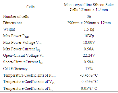
The module photovoltaic is used to harvest sunlight and actively convert it to electricity. The conversion of sunlight to become a usable electrical energy is called the ‘photovoltaic effect’. Solar cells are also called photovoltaic cells are typically constructed with crystalline silicon and arranged in a grid-like pattern on the surface of the solar panel. The more amounts and quality of solar cells in a solar panel, the more total electrical output the solar panel will produce. It’s difficult to give an exact value of output because different types of solar panel will come out with distinct output and average percentage of efficiency. For this project, types of mono crystalline silicon cells are suitable for use as an input generating electric. Mono or single crystalline silicon cells are made from very pure mono crystalline silicon and have a single and continuous crystal lattice structure with almost no defects or impurities. This type of solar panel is most efficient (17%) as in converting the sunlight absorbed into electricity. Therefore, it is the most expensive. It can do better in lower light condition than the other types of solar panel. Figure 1 shows the solar panel mono crystalline silicon cells and Table 1 shows the specification of solar panel.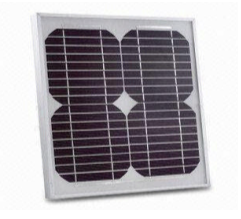 | Figure 1. Mono crystalline silicon cells |
Table 1. Specification of solar panel
 |
| |
|
2.2. Battery Lead Acid
A battery is a device that converts chemical energy contained in its active material into electricity. A battery consists of two or more cells connected in series or parallel. However the term “battery” is also used for single cells. A typical battery cells consist of a liquid, paste or solid electrolyte, a positive electrode and a negative electrode. The electrolyte is an ionic conductor. When the electrodes are connected to load, one of the electrodes will react and producing electron, while the other will accept electrons. This action will cause electrical current flows through the load. Batteries, in which the chemicals cannot be reconstituted into their original form once the energy has been converted or battery has been discharged are called primary cell or voltaic cells. Batteries in which the chemicals can be reconstituted by passing electric current through them in the direction opposite that of normal cell operation are called secondary cells, rechargeable cells, storage cells or accumulators. Lead acid battery which is shown in Figure 2.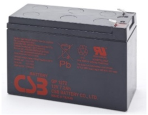 | Figure 2. Battery lead acid |
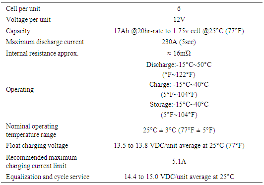
The characteristic of Lead Acid Battery is shown in Table 2. Normally, the lead acid battery does not lend itself to fast charging, typical charge times are 8 to 16 hours depends on the characteristic solar panel and sunlight day.Table 2. Specification of battery lead acid
 |
| |
|
3. Hardware Development
This research is adopting methods approach involving some developments to enhance the portable case solar battery charger project. Which, it is discuss about the circuits that used at every part in project system and mains component involving at every that part.
3.1. Hardware Design
The portable case solar battery charger design has four view positions such as front, top, left, and trimetric. The dimension of the case is the length × width × height = 400mm × 340mm × 220mm that suitable for place the battery, solar panel, inverter and circuit inside portable case. Figure 3 shows the hardware design using Solidwork software. 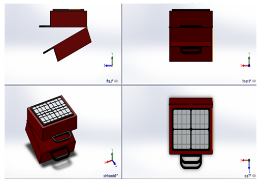 | Figure 3. Hardware design |
3.2. Converter Circuit
In the simulation, the battery supplies a voltage of 12V DC input circuit.1N4007 diode D1 component that is used to keep the current flowing in one direction only and to prevent current flow back to the battery. While the capacitors C1 and C2 which are used to store charge in the circuit. Next, input from 12V battery will be regulated by the LM7805 component of the voltage converter to produce a constant output voltage at 5V. In this circuit system component of the switch SW1 is used to control whether the circuit during operation or not in operation. This circuit use for supply 5V DC voltage to USB port. Figure 4 shows the converter circuit 5V DC design using Protues 8 Profesional software.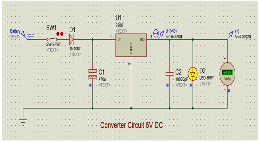 | Figure 4. Converter Circuit 5V DC |
3.3. Battery Charging Circuit
Figure 5 shows the battery charger circuit using LM317 IC component as the main component for controlling the output voltage. In this circuit the voltage is determined by controlling the resistance of the resistor RV1 component adjustable. During the process of charging the battery on a BC547 transistor Q1 will control battery voltage. If the battery voltage is full, the BC547 will act as switches to slow charging and turn off the battery charge. Diode in the D2 functions as determining the current flow is in one direction so that the battery does not flow into the solar panel, which can cause damage. Battery charger circuit system is controlled by switches on SW1 to switch off and switch on the circuit.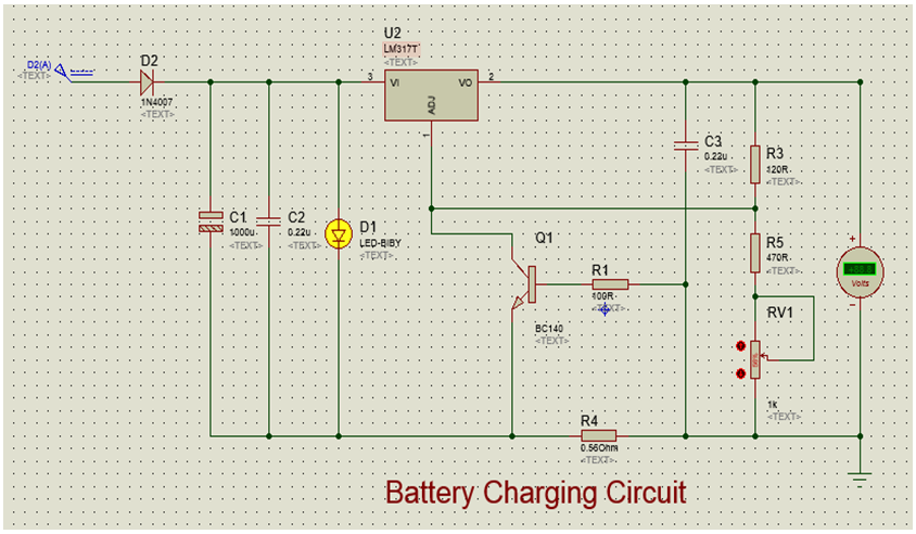 | Figure 5. Battery charging circuit |
3.4. Battery Level Indicator Circuit
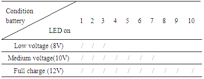
The main component this circuit is LM3914 display driver IC is used to convert the battery voltage to indicate leds. The IC LM3914 can operate with a wide range of supply voltage (3V to 25V DC). We can control the brightness of led by using variable resistor RV2. In this project battery level indicator circuit used for give information about state of battery whether low, medium or full charges. That is precaution step when overcharging occur and easy to monitor the condition of battery.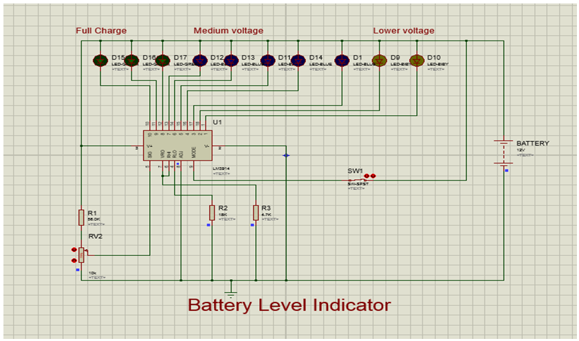 | Figure 6. Battery level indicator circuit |
3.5. Converter Circuit 12V DC and 9V DC
The converter circuit 9V DC and 12V DC uses as the input voltage for the cooling fan and the digital meter. The main component in this circuit is the LM7809 and LM7812 as to produce a constant voltage. Figure 7 shows converter circuit 12V DC and 9V DC.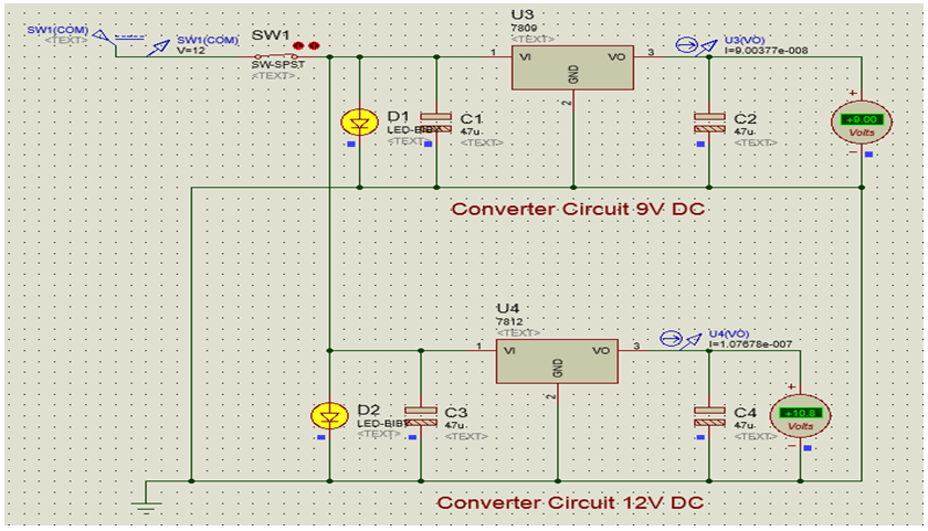 | Figure 7. Converter circuit 12V DC and 9V DC |
4. Results and Analysis
This section discusses about results for each circuit or hardware used should be tested for its effectiveness. In addition, this section also shows a prototype of project has been built.
4.1. Analysis Solar Panel
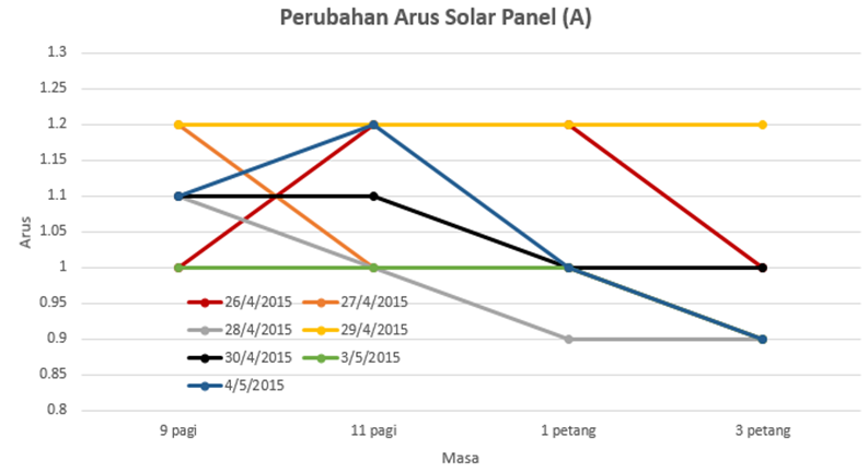
From this analysis, the value that can be generated by solar panels with practically almost on the specifics of the solar panels. This means that solar panels used in good condition. In addition, the solar panel voltages value depends on the weather e.g: bright or cloudy. Meanwhile, the current changes in solar panel changes depending on the temperature. The maximum voltage of solar panel is on 30th April 2015. In other hands, the maximum of current solar panel is on 29th April 2015. Figure 8 shows the changes of voltage solar panel and Figure 9 shows the changes of current solar panel.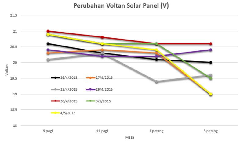 | Figure 8. The change of voltage solar panel |
 | Figure 9. The change of current solar panel |
4.2. Results of Battery Charging
From this analysis, the battery charge is dependent on weather conditions. Therefore, the peak time is chosen from 9am until to 3pm. Besides that, the battery charging without load the voltage rises more than the battery charging using loads e.g. mobile phone or laptop. Figure 10 shows the voltage of battery charging without the load and Figure 11 shows the voltage of battery charging with the load.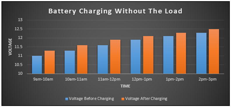 | Figure 10. The Voltage of battery charging without the load |
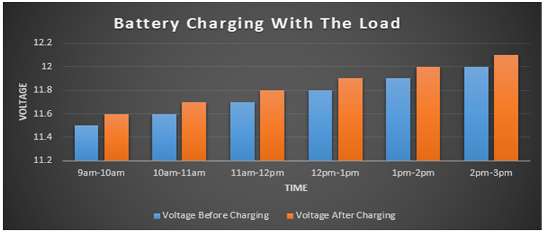 | Figure 11. The Voltage of battery charging with the load |
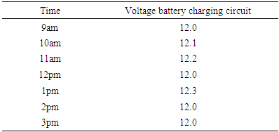
The battery charging circuit analysis was taken for 6 hours in 1 day and data are taken every 1 hour. This process is carried out in hot weather and cloudy. Table 3 shows the data for the battery charger circuit which is taken for 6 hours and Figure 12 shows the output waveform generated straight on 12V DC voltage using the oscilloscope.Table 3. Results of battery charging circuit
 |
| |
|
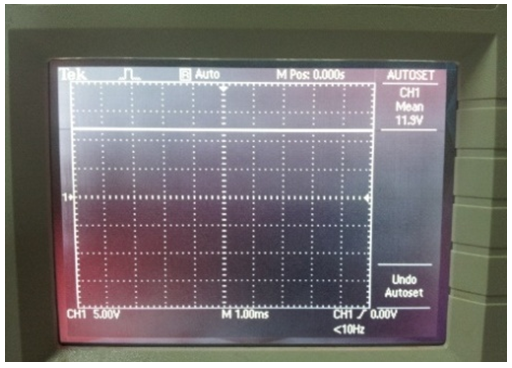 | Figure 12. The Voltage Waveform of Battery Charging Circuit |
4.3. Results of Converter Circuit 5V DC
In analysis data 5V DC converter circuit by used equipments are the multi-meter and an oscilloscope to observe the output. Output 5V DC of this circuit will be connected to the Universal Serial Bus (USB) for charging mobile phones. From practical analysis the output voltage is same with simulation value. Table 4 shows the results of converter circuit 5V DC and Figure 13 shows the voltage waveform of converter circuit 5V DC.Table 4. Results of converter circuit 5V DC
 |
| |
|
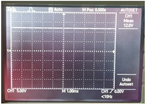 | Figure 13. Waveform converter circuit 5V DC |
4.4. Results of Battery Indicator Circuit
In this project the battery voltage level indicator circuit used for precautions to make sure the battery is charged does not exceed the ability to keep the voltage. With this circuit, the battery can be monitored more easily. So battery life can last longer. Table 5 shows results of battery indicator circuit.Table 5. Results of Battery Indicator Circuit
 |
| |
|
4.5. Results of Converter Circuit 12V DC and 9V DC
In this project 9V DC converter circuit is used to the supply voltage for the cooling fans. In addition, the 12V DC converters circuit is used to the supply voltage of digital meters. Table 6 shows the converter circuit 12V DC and 9V DC from a multi-meter.Table 6. Results of converter circuit 12V DC and 9V DC
 |
| |
|
4.6. Results of Inverter Circuit
The inverter device in the project is used to convert direct current (DC) to alternating current (AC) output. The inverter used for high voltage equipment. This analysis is intended to ensure that the results are practically same as the specifications contained in this inverter device. Table 7 show the data inverter device taken during the analysis is performed using the multi-meter. Figure 14 shows the waveform sine of inverter device.Table 7. Results from the inverter circuit
 |
| |
|
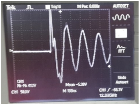 | Figure 14. Waveform inverter circuit |
4.7. Prototype of Project
Figure 15 shows the prototype portable case solar battery charger that made of wood and aluminum materials in the production of a cassis which can be carried anywhere and can generate high voltage for use electrical and electronic equipment.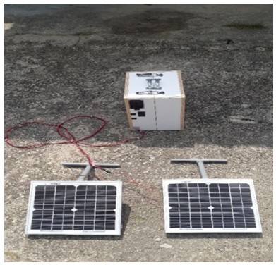 | Figure 15. Prototype portable case solar battery charger |
5. Conclusions
From this project, the charging circuit is designed to be able to charge the battery at peak hour. Meanwhile the battery level indicator circuits are able to detect condition of battery. In addition, the converter circuit 5V DC and inverter device are capable to produce output for loads especially for electronic and electrical equipment. This project has reach its goal of producing a solar system that can generate output AC and DC as well as convenient to be carried anywhere.
References
| [1] | Mahadi Bin Abidin, “Solar Battery Charger Using PIC Controller” University Tun Hussein Onn 2010. |
| [2] | Ng Peir Zuen, “Thesis Portable Solar Charger” University Tun Hussein Onn 2011. |
| [3] | Md Zamdil bin Md Zapin “Lighthouse Using Automatic Solar Charging Systems” University Tun Hussein Onn 2009. |
| [4] | Mohd Azlee bin Hj Zainal “Electric Fence Using Solar Energy” University Tun Hussein Onn 2012. |
| [5] | Aizuddin bin Abd Rahim “Portable Solar Powered Battery Charger” University Tun Hussein Onn 2010. |
| [6] | Deo Prasad and Mark Snow “Solar Power” University of New South Wales, Australia 2005. |
| [7] | Tomas Markvart “Solar Electricity” University of Southampton, UK 2000. |


 Abstract
 Reference
 Full-Text PDF
 Full-text HTML


