-
Paper Information
- Previous Paper
- Paper Submission
-
Journal Information
- About This Journal
- Editorial Board
- Current Issue
- Archive
- Author Guidelines
- Contact Us
Electrical and Electronic Engineering
p-ISSN: 2162-9455 e-ISSN: 2162-8459
2016; 6(3): 49-54
doi:10.5923/j.eee.20160603.02

New Technique for Cluster Identification of FACTS Placement
 Abstract
 Reference
 Full-Text PDF
 Full-text HTML
Siti Amely Jumaat1, Ismail Musirin2, Nur Hanis Mohamad Radzi1
1Faculty of Electrical and Electronics Engineering, Universiti Tun Hussein Onn Malaysia, Batu Pahat, Malaysia
2Faculty of Electrical Engineering, Universiti Teknologi MARA, Shah Alam, Malaysia
Correspondence to: Siti Amely Jumaat, Faculty of Electrical and Electronics Engineering, Universiti Tun Hussein Onn Malaysia, Batu Pahat, Malaysia.
| Email: |  |
Copyright © 2016 Scientific & Academic Publishing. All Rights Reserved.
This work is licensed under the Creative Commons Attribution International License (CC BY).
http://creativecommons.org/licenses/by/4.0/

This paper presents a new technique to identify the cluster of FACTS device placement in power system network. The technique is Evolutionary Particle Swarm Optimization (EPSO) with objective function to minimize the transmission loss of the system. Tests were performed on the IEEE-118 RTS to realize the effectiveness of the proposed technique, while verification was conducted through comparative studies with Evolutionary Programming (EP) and Particle Swarm Optimization (PSO).
Keywords: Static var compensator, Transmission loss, Evolutionary particle swarm optimization
Cite this paper: Siti Amely Jumaat, Ismail Musirin, Nur Hanis Mohamad Radzi, New Technique for Cluster Identification of FACTS Placement, Electrical and Electronic Engineering, Vol. 6 No. 3, 2016, pp. 49-54. doi: 10.5923/j.eee.20160603.02.
Article Outline
1. Introduction
- Electric utilities are forced to manage the systems close to their thermal and stability limits due to major hurdles such as environmental, right-of-way and cost problems for the power transmission network expansion [1]. Hence, there is an interest for better utilization of available capacities by installing Flexible AC Transmission Systems (FACTS) Devices to minimize the transmission loss. FACTS device can help decrease the flows in heavily loaded lines, resulting in raised loadability, low system loss, improved stability of the network, reduced cost of production and fulfilled contractual requirement. They can enable lines to flow the power near its nominal rating and maintain its voltage within the desired level while enhancing power system security during contingencies [2-4]. For a meshed network, an optimal location of FACTS device allows to control its power flow and also to improve the system loadability and the security [5]. The effect of FACTS device on power system security, reliability and loadability has been studied according to proper control objectives as reported in [5-7]. Researchers have tried to find suitable location for FACTS device to improve power system security and loadability in [8-11].This paper presents a new technique to develop cluster of SVC installation in power system network. The technique is Evolutionary Particle Swarm Optimization (EPSO) with objective function to minimize the transmission loss of the system. Tests were performed on the IEEE-118 RTS to realize the effectiveness of the proposed technique, while verification was conducted through comparative studies with Evolutionary Programming (EP) and Particle Swarm Optimization (PSO).
2. Static Var Compensator (SVC)
- The Static Var Compensator (SVC) is a shunt-connected static VAR generator or absorber whose output is adjusted to exchange capacitive or inductive current so as to maintain or control specific parameters of the electrical power system (typically bus voltage [12, 13]. SVC helps to maintain a bus voltage at a desired value during load variations. It injects or absorbs its reactive power, QSVC at a chosen bus. It injects reactive power from the system if QSVC<0 and absorbs reactive power from the system if QSVC >0 [14]. The working range of SVC is 0MVar until +100MVar. The principle of shunt reactive power (var) compensation as illustrated in Figure 1 and the SVC is modeled as a generator or absorber of reactive power as shown in Figure 2.
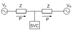 | Figure 1. SVC Installation on a Transmission Line |
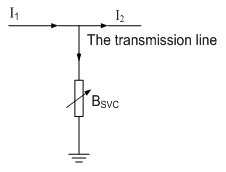 | Figure 2. Current Flow Directions with SVC Installation |
3. Evolutionary Particle Swarm Optimization (EPSO)
- Several methods have been applied to solve power system problem in recent years, such as Evolutionary PSO (EPSO) [15-17], improved PSO [18, 19], and adaptive PSO [20] Z.A Vale et al [20] present a method to placement reactive power compensation using EPSO technique to find the best operation point for minimizing power losses. EPSO [21-24] is an improved version of traditional PSO with additional Mutation to the strategic parameters and Selection, by Stochastic Tournament, of particles passing to the next movement iteration. In terms of particle swarms, EPSO relies on involving weights in the movement equation, instead of an explicit random factor. Therefore, EPSO is less dependent on parameter externally defined by the user. EPSO has proven to be efficient, accurate and robust, with successful applications to power system problem [21, 26]. G. Baskar et. al [27] proposed improved PSO, PSO, EP, fast-EP, and Mean Fast-EP technique to alleviate line overloading for contingency constrained economic load dispatch (CCELD) with win objectives function are minimization of fuel cost and minimization of severity index. IPSO method has stable convergence characteristics and non-oscillatory which gives minimum fuel cost. Jong-Bae Park et. al [28] present an efficient approach for solving economic dispatch problems with non-convex cost functions using IPSO. The proposed IPSO is applied to three different non-convex economic dispatch problems with valve –point effects, prohibited operating zones with ramp rate limits as well as transmission network losses, and multi-fuels with valve-points effects. The general scheme of EPSO is given in the following operators: a) Initialization – to generate random numberb) Replication – each particle is replicatedc) Mutation - each position and velocity has its strategic parameters mutated. Reproduction – each mutated particle and velocity generates an offspring according to the particle and velocity movement rule. d) Evaluation – each offspring has its fitness evaluatede) Selection – by stochastic tournament or order selection procedure, the best particles survive to form a new generation. The general flowchart for EPSO is shown in Figure 3.
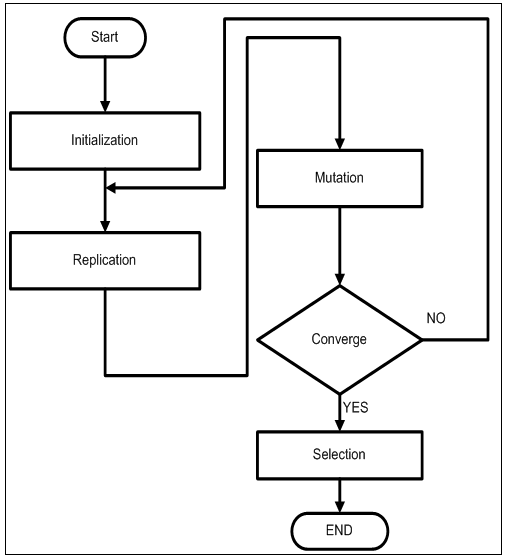 | Figure 3. Flowchart of General Evolutionary Particle Swarm Optimization (EPSO) Process |
4. Results and Discussion
- Validation of the proposed technique has been conducted on the IEEE 118-RTS. The size and location are conducted through offline study so as to avoid the system from experiencing over compensation or under compensation. The SVC installation in the system is conducted when load increased of 50, 100, 150 and 180MVar subjected to buses 20 of IEEE-118 RTS.
4.1. SVC Installation
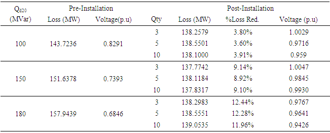
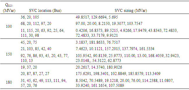
- In order to enhance the breadth of the study, similar process was performed to IEEE 118-Bus RTS. For this system, the load variation is increased to 180MVar before the system collapse is subjected to buses 20 and 53 respectively. Results of the transmission loss minimization when load variation is subjected to bus 20 are tabulated in Table 1. Results of location and sizing of SVC when loading variation is subjected to Bus 20 are tabulated in Table 2. For example, when load is increased to 100MVar at Bus 20, the transmission loss is minimized to 138.1MW (3.91% reduction) when ten units of SVC are installed into the system and the voltage is improved to 0.959p.u.. Subsequently, when load is increased to 150MVar, the transmission loss is minimized to 137.7742MW (9.14% reduction) with three units of SVC are installed into the system; while voltage is improved to 1.0047p.u.. Besides that, when load is increased to 180MVar at bus 20, the transmission loss is minimized to 138.2983MW (12.44% reduction) when three units of SVC are installed into the system. Also, the voltage is improved to 0.9767p.u.. The location and size of SVC when loading variation is subjected to bus 20 are tabulated in Table 2. For instance, the optimal location and sizing of SVC installation when Qd20=100MVar are buses 11, 115, 20, 63, 92, 25, 64, 111, 30, and 98 with 0.4206MVar, 16.8373MVar, 89.5215MVar, 4.9266MVar, 17.9479MVar, 43.8343MVar, 72.4833MVar, 72.4833MVar, 33.7179MVar, 9.9121MVar, respectively. On the other hand, the optimal location of SVC installation when Qd20=150MVar are buses 45, 20, and 75 with the sizing are 3.1837MVar, 181.8633MVar, 76.7517MVar, respectively. In addition, the optimal location and sizing of SVC installation when Qd20=180MVar are buses 19, 37, 20 with the sizing are 20.2617MVar, 14.3740MVar, and 180.9026MVar, respectively. From the results, three units of SVC installed into the system give better performance in terms of transmission loss reduction when loading variation is subjected to Bus 20.
|
|
4.2. Cluster Identification
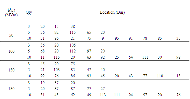
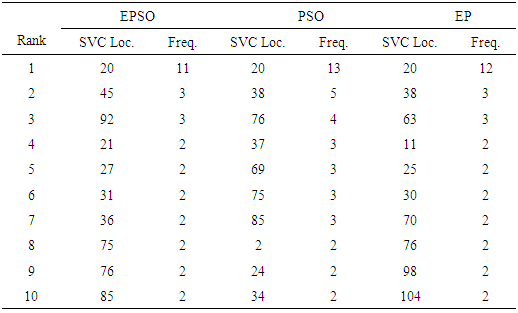
- The cluster identification for the IEEE 118-bus system was conducted by looking at the frequency of such buses chosen for the SVC installation. In other words, the participated buses are monitored for each installation i.e. for 3 SVC, 5 SVC and 10 SVC installations [38]. Table 3 tabulates the results for SVC installation when load variation is subjected to Bus 20 in the system. Besides that, Table 3 tabulates the ranking of SVC installation based on the frequency of particular buses chosen for SVC installation via EPSO, PSO and EP. From Table 3 and Table 4, when load is increased to 180MVar, the top-ten locations are chosen to form the clusters using EPSO method are buses 20, 45, 92, 21, 27, 31, 36, 75, 76, and 85. These buses are closely connected to bus 20. The top-ten locations chosen to form the clusters via PSO and EP technique are tabulated in the same table. The buses are highlighted in the system to form the clusters via EPSO, PSO and EP techniques as illustrated in Figure 4. From Table 4 and Figure 4 it is observed that buses 20 and 76 in the rank of cluster formation using EPSO, PSO and EP techniques.
|
|
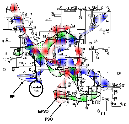 | Figure 4. Cluster Identification of SVC Installation when Load Variation is subjected to Bus 20 Using EPSO, PSO and EP |
5. Conclusions
- This paper has presented Evolutionary Particle Swarm Optimization Technique for Optimal Location and size of and Cluster Identification. In this study, location and size of SVC installation with single objective function has be implemented to minimize the transmission loss, while monitoring the voltage profile. The proposed technique was implemented on IEEE 118-bus system buses 20 are subjected to loading variation condition respectively. Next, results obtained from the EPSO technique were compared with PSO and EP. Experiment results demonstrated that the proposed EPSO technique is feasible for loss minimization scheme in other power system network. It was found that EPSO is superior with respect to PSO and EP techniques in most cases. Finally, the results also presented the formation of cluster for SVC installation in power system. The clusters were formed based on the frequency of particular buses chosen for the SVC installation into the system. As the conclusion, the clusters of SVC installation are located close to the weak buses. The results and proposed technique from this study could be used by power system planner in order to perform loss minimization scheme in their system.