Hoo Choon Lih
School of Engineering, Taylor’s University, Subang Jaya, Malaysia
Correspondence to: Hoo Choon Lih, School of Engineering, Taylor’s University, Subang Jaya, Malaysia.
| Email: |  |
Copyright © 2016 Scientific & Academic Publishing. All Rights Reserved.
This work is licensed under the Creative Commons Attribution International License (CC BY).
http://creativecommons.org/licenses/by/4.0/

Abstract
Motor control, regardless of for speed or position, is very important in the industry especially with the increasing demand for electric motor in various industrial applications. Windup is a common challenge in electric motors when controlled using a PI controller especially when it is designed to work close to its saturation region. Windup happens when a control system falls under a saturated control state that causes the system to experience overshoot and even instability. PI controlled system will also experience tuning gain coupling, where it is not possible to tune the contribution of each control (proportional or integral) independently. This restrains the possibility of having short settling time with no overshoot performance. A novel anti-windup PI controller, SIPIC, was proposed and shown to have a good response in permanent magnet synchronous motor speed control application with field oriented control. The closed-loop integral with reference set fed by input command and external torque structure allows the system to quickly regain unsaturated control. SIPIC also reduces the tuning gain coupling effect which gives more flexibility in obtaining desired short settling time with no or little overshoot. The PSIM simulation result shows that the SIPIC exhibit little to no overshoot and faster recovery torque performance compared to the conventional PI controller for both no load and loading step response conditions.
Keywords:
Anti-windup, Proportional-integral, Speed control, Permanent magnet synchronous motor, Field oriented control
Cite this paper: Hoo Choon Lih, The Application of Anti-windup PI Controller, SIPIC on FOC of PMSM, Electrical and Electronic Engineering, Vol. 6 No. 3, 2016, pp. 39-48. doi: 10.5923/j.eee.20160603.01.
1. Introduction
The Proportional-Integral (PI) controller still gained a lot of interest from many in the field of motor control. The application includes motor speed and position control on field oriented control for direct current (DC) motor, induction motor (IM) and permanent magnet synchronous motor (PMSM) [1]. Recently work has been explored into indirect FOC which consist of decoupled torque and flux components for high performance application [2]. Some comparison works show that Fuzzy pre-compensated PI [3] and Model Predictive Control (MPC) [4] are better than conventional PI controller. PI controller is easy to implement in the control system with established tuning theory and analytical study. However, PI suffers from saturated control state due to the integral control which termed as windup. Windup phenomenon happened when the PI control output exceeds the limit of the system plant input. The control system is said to be saturated and the system is not controllable which may introduce instability. Furthermore, PI controller also experience tuning difficulty. Despite having comprehensive tuning method, the PI control structure leads to the coupling of tuning parameter, kp and ki. Tuning of kp will affect the contribution of ki and vice versa due to their dependency. This results in the complication in having short settling time under no overshoot performance.Many works have been done in introducing anti-windup controllers that aim to bring the control back to the unsaturated state as soon as possible. The most commonly discussed anti-windup techniques include the conditioning [5], Tracking back calculation [6] and Integral State Prediction [7] methods. The methods differ in their way of controlling their integral control in order for the control system to quickly regain the unsaturated control.In year 2015, [8] studied on the possibility in decoupling the tuning gain. References [9, 10] proposed a new anti-windup, Steady-state Integral PI Controller (SIPIC) which contains the ability to decouple the tuning gains without the need to switch between two control methods as how conventional anti-windup controllers did. SIPIC has its separate integral loop fed by the steady state integral value that consistently drives the integral control towards the steady state integral value. The system was shown to perform better with smaller overshoot while able to tune the rise time and settling time as compared to the other conventional PI and anti-windup PI controller [9, 10] on a DC motor speed control.This research intends to investigate the application of SIPIC on FOC of PMSM on speed control. Only simulation work was considered in this work. This paper will continue with Section 2 that explain the dynamical equation of a generic control system. Section 3 will discuss about SIPIC while Section 4 describes the working principle of FOC. Simulation setup and results will be discussed in Section 5 and 6 respectively. This paper ends with a summary of the overall work.
2. Dynamical Control System
Figure 1 shows the block diagram of a general PI control system. The PI output will be constrained by the limiter which restrains the PI control output from exceeding certain safe voltage/current value to prevent any damage to the hardware component. This limitation is responsible for the study of saturated control that leads to the anti-windup control. Saturated control system will cause the system uncontrollable and even introduce instability. This is usually observed as the overshoot in system response. The anti-windup control aims to bring the control system into the unsaturated state to regain the control.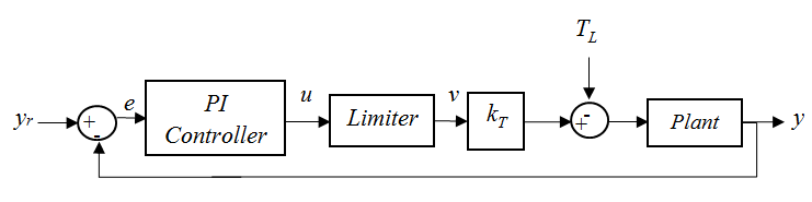 | Figure 1. PI controller in a closed loop system |
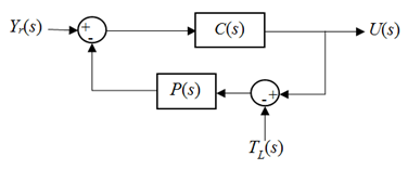
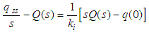
To derive the controller’s output signal, the signal is taken as the output of a closed loop system as depicted in Figure 2. The output of the controller can be deduced as detailed in Equation (1).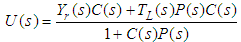 | (1) |
 | Figure 2. Closed loop system with the control signal as the output |
Since the both PI controller and SIPIC consist of the proportional and integral components, the controller Laplace form can be expanded into (2) and substituting into Equation (1) results in (3).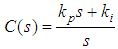 | (2) |
 | (3) |
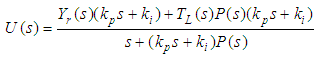
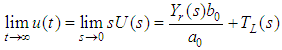
For an nth order plant with a generic transfer function as described in Equation (4), it can be shown that the DC gain of the PI controller in the closed-loop configuration depicted in Figure 2 at steady state is as described in Equation (5). The steady state output of a PI controller is affected by the input reference, parameters from the plant and the torque affecting the system.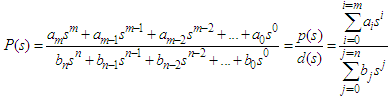 | (4) |
 | (5) |
3. SIPIC
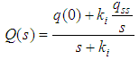
References [9, 10] discussed that any controller that requires zero steady state error must satisfy condition (6). Based on this understanding, the authors proposed a new anti-windup PI controller, SIPIC (Steady-state Proportional Integral Controller) with the structure as given by equation (7). SIPIC works under the approach where its integral control has a separate loop that fed with integral steady state value. Equation (8) denotes the integral control form of a SIPIC. The SIPIC method has decoupled kp and ki which could be tuned to have no overshoot and still maintain a zero steady state error. For conventional PI controller, a short rise time response will always induces overshoot.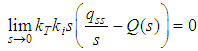 | (6) |
 | (7) |
 | (8) |
4. Field Oriented Control
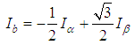
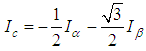
In a FOC (field oriented control), there are a few signal (abc-αβ-dq) transformation phases. The transformation is performed by Park, Clarke and their respective inverse transformations. This allows conversion of fixed/rotating referencing axes signal type in different phases of the control system. The signals can be obtained by the following the transformation formulae (9)-(17):Clarke Transformation: Convert 3 phase current/voltage into stationary reference frame (α-β). | (9) |
 | (10) |
Park Transformation: Convert current/voltage from stationary reference frame (α-β) to rotating reference frame (d-q).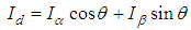 | (11) |
 | (12) |
Inverse Park Transformation: Convert current/voltage from rotating reference frame (d-q) to stationary reference frame (α-β). | (13) |
 | (14) |
Inverse Clarke Transformation: Convert current/voltage from stationary reference frame (α-β) into 3 phase current/voltage. | (15) |
 | (16) |
 | (17) |
The inverter converts DC (direct current) to AC (alternating current) and its conversion can be done with the SVM (Space Vector Modulation) method. The conventional SVM can be performed with 6 IGBTs (insulated-gate bipolar transistors) in producing 3 phase voltage and current. The generated switching pattern from the PWM (pulse width modulation) gives the switching sequence for the IGBTs in producing the corresponding AC with respect to the desired angle within one period which complete the DC to AC conversion process.
5. Simulation Setup
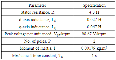
A simulation has been attempted with the circuit as shown in Figure 3 using the PSIM & CPad for Borland C++ compiler software in order to compare the motor speed performance of conventional PI controller and SIPIC. The CPad for Borland C++ compiler is meant to create the dll block in performing the PWM function. The specification of the PMSM (permanent magnet synchronous motor) is given in Table 1 while the current regulator has been tuned according to the conventional method as given by (18)-(21). | (18) |
 | (19) |
 | (20) |
 | (21) |
Table 1. Specification of the PMSM
 |
| |
|
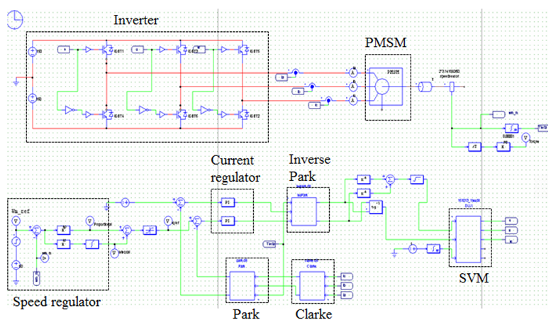 | Figure 3. FOC structure in PSIM |
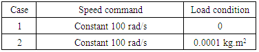
Figure 4 depicts the block diagram of SIPIC as reflected by (7) in PSIM used for the simulation. The simulation was performed in four cases that require different speed input command and loading condition as detailed in Table 2. For each of the cases, the tuning parameters of the speed regulator will be simulated for kp=1 and ki=1, kp=1 and ki=2, kp=1 and ki=3, kp=2 and ki=1, and kp=3 and ki=1. This selection of tuning parameters is meant to show a significant difference of the performance between the two controllers.Table 2. Simulation Cases
 |
| |
|
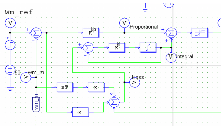 | Figure 4. SIPIC in PSIM |
6. Simulation Results
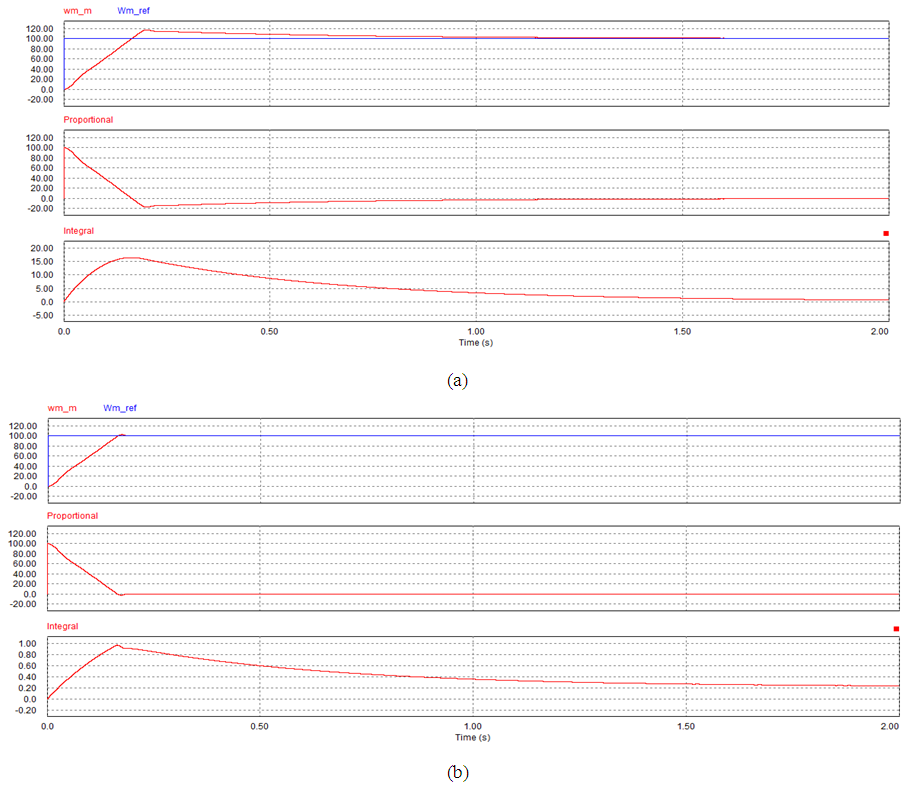
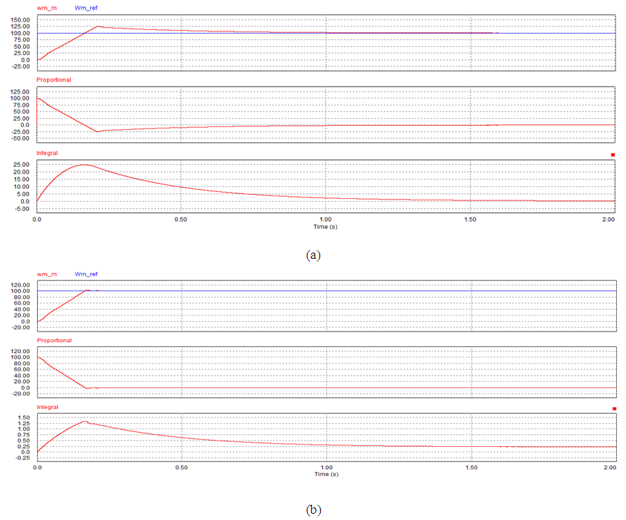
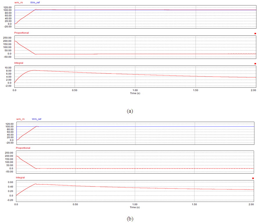
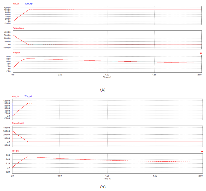
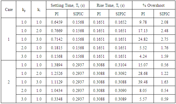
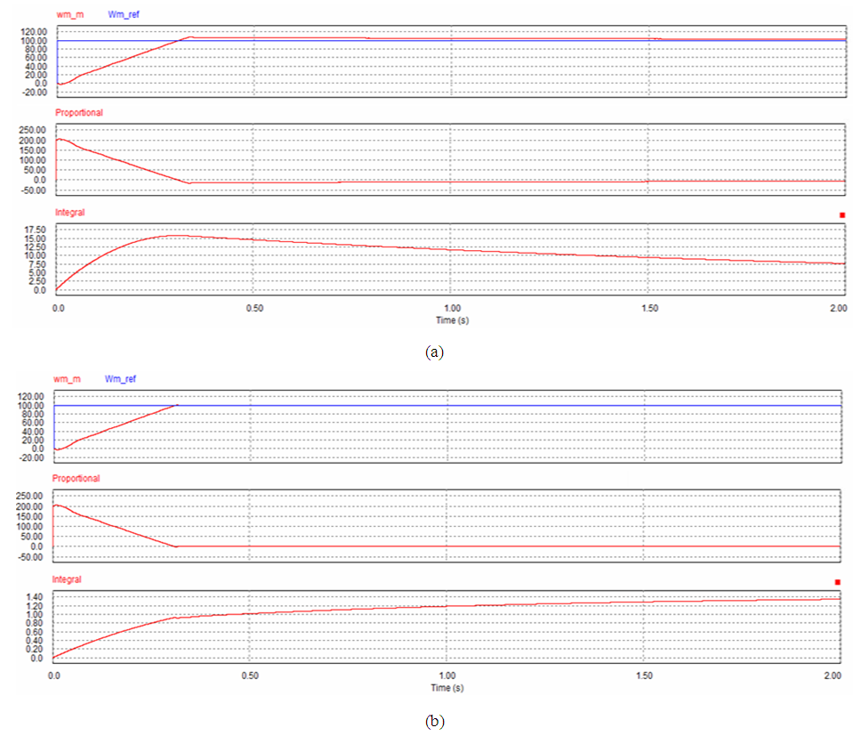
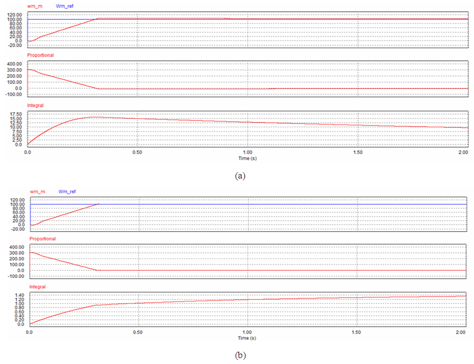
6.1. Case 1
Figure 5 to Figure 9 show the speed performance comparison between a PI controller and SIPIC for case 1 with respect to different tuning parameters. However the analytical work has been summarised in Table 3 in terms of the settling time, rise time and percentage overshoot. In case 1, PI and SIPIC do not show much change in their rise time. However, SIPIC has the shortest settling time regardless of any tuning parameters change. This can be explained by the integral control of SIPIC, which attains steady state integral value earlier than the PI controller. PI controller and SIPIC exhibit increasing overshoot with ki value, but SIPIC has a very minimal overshoot percentage. | Figure 5. Simulation result for case 1 at kp=1 and ki=1. (a) PI. (b) SIPIC |
 | Figure 6. Simulation result for case 1 at kp=1 and ki=2. (a) PI. (b) SIPIC |
 | Figure 7. Simulation result for case 1 at kp=1 and ki=3. (a) PI. (b) SIPIC |
 | Figure 8. Simulation result for case 1 at kp=2 and ki=1. (a) PI. (b) SIPIC |
 | Figure 9. Simulation result for case 1 at kp=3 and ki=1. (a) PI. (b) SIPIC |
Table 3. Summary of the Simulation Result
 |
| |
|
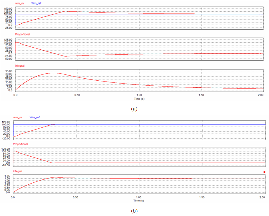
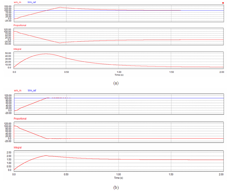
6.2. Case 2
Figure 10 to Figure 14 give the speed response, Proportional and integral control comparison between a PI controller and SIPIC for case 2 with respect to different tuning parameters. The same observation can be seen for case 2 with loading condition. Even though PI controller has short rise time, this accompanied by large overshoot percentage. SIPIC allows the adjustment of rise time through increasing tuning parameters without affecting much on the overshoot. This is due to the tuning parameter decoupling effect of a SIPIC where the change of a tuning parameter, kp will not greatly affect the contribution of ki. This indirectly indicates that the change in tuning parameter will not drastically affect the damping state of SIPIC, which then allows more flexible tuning range for co-existence of minimal overshoot and no steady state error response.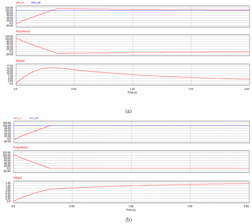 | Figure 10. Simulation result for case 2 at kp=1 and ki=1. (a) PI. (b) SIPIC |
 | Figure 11. Simulation result for case 2 at kp=1 and ki=2. (a) PI. (b) SIPIC |
 | Figure 12. Simulation result for case 2 at kp=1 and ki=3. (a) PI. (b) SIPIC |
 | Figure 13. Simulation result for case 2 at kp=2 and ki=1. (a) PI. (b) SIPIC |
 | Figure 14. Simulation result for case 2 at kp=3 and ki=1. (a) PI. (b) SIPIC |
7. Conclusions
SIPIC can be applied on FOC PMSM control and show an improved motor speed performance as compared to the conventional PI controller. The simulation result shows that SIPIC has lower overshoot percentage and short settling time regardless of the loading condition. PI controller may have smaller rising time in loading condition, however PI controller exhibits larger overshoot. This shows that SIPIC is potentially applicable to FOC motor control, which serves to be an alternative method in motor control field where anti-windup is required. However, the simulation was only done for constant speed, further simulation need to be performed on changing input command to determine its robustness. SIPIC will also be experimentally tested for different speed and other application for further verification.
ACKNOWLEDGEMENTS
This work was inspired by the collaboration research in Sakura Science Exchange Program and supported by the TRGS under grant TRGS/ERFS/1/2015/SOE/018.
References
| [1] | X. Zhang, X. Xie and R. Yao, "Field oriented control for permanent magnet synchronous motor based on DSP experimental platform," in 2015 27th Chinese Control and Decision Conference (CCDC), Qingdao, 2015. |
| [2] | S. Chacko and S. Jain, "TS -Fuzzy controller based rotor resistance estimation for indirect field oriented controlled IM drive utilizing rotor flux," in 2014 Annual IEEE India Conference (INDICON), Pune, 2014. |
| [3] | G. Singh and G. Singh, "A fuzzy pre-compensated-PI controller for indirect field oriented controlled induction motor drive," in 2014 Innovative Applications of Computational Intelligence on Power, Energy and Controls with their impact on Humanity (CIPECH), Ghaziabad, 2014. |
| [4] | A. A. Z. Diab, D. A. Kotin, V. N. Anosov and V. V. Pankratov, "A comparative study of speed control based on MPC and PI-controller for Indirect Field oriented control of induction motor drive," in 2014 12th International Conference on Actual Problems of Electronics Instrument Engineering (APEIE), Novosibirsk, 2014. |
| [5] | J. K. Seok, “Frequency-spectrum-based antiwindup compensator for PI controlled systems,” IEEE Trans. Ind. Electron., Vol. 53, No. 6, pp. 1781-1790, Dec. 2006. |
| [6] | H.-B. Shin, “New antiwindup PI controller for variable-speed motor drives,” IEEE Trans. Ind. Electron., Vol. 45, No. 3, pp. 445-450, Jun. 1998. |
| [7] | H.-B. Shin and J.-G. Park, “Anti-Windup PID Controller With Integral State Predictor for Variable-Speed Motor Drives,” IEEE Trans. Ind. Electron., Vol. 59, No. 3, pp. 1509-1516, Mar. 2012. |
| [8] | C. L. Hoo, S. M. Haris, E. C. Y. Chung and N. A. N. Mohamed, "The Generalisation and Decoupling Mode of PI-Based Control: Theoretical Approach," ICIC Express Letters, vol. 9, no. 7, pp. 1991-1996, 2015. |
| [9] | C. L. Hoo, S. M. Haris, E. C. Y. Chung and N. A. N. Mohamed, "New Integral Antiwindup Scheme for PI Motor Speed Control," Asian Journal of Control, vol. 17, no. 6, pp. 2115-2132, November 2015. |
| [10] | C. L. Hoo, S. M. Haris, E. C. Y. Chung and N. A. N. Mohamed, "Steady-State Integral Proportional Integral Controller for PI Motor Speed Controllers," Journal of Power Electronics, vol. 15, no. 1, pp. 177-189, 2015. |

 Abstract
 Reference
 Full-Text PDF
 Full-text HTML