-
Paper Information
- Paper Submission
-
Journal Information
- About This Journal
- Editorial Board
- Current Issue
- Archive
- Author Guidelines
- Contact Us
Electrical and Electronic Engineering
p-ISSN: 2162-9455 e-ISSN: 2162-8459
2016; 6(1): 11-17
doi:10.5923/j.eee.20160601.03

Slot Loaded Square Microstrip Patch Antenna for Dual Band Operation
 Abstract
 Reference
 Full-Text PDF
 Full-text HTML
Faria Jaheen 1, Abdullah Al Noman Ovi 2, Marjan Akhi 3
1Department of Electrical & Electronics Engineering, American International University-Bangladesh, Dhaka, Bangladesh
2Department of Electrical & Electronics Engineering, Faculty of Engineering, Purdue University, West Lafayette, United States
3Department of Electrical & Electronics Engineering, Faculty of Engineering, Ahsanullah University of Science and Technology, Dhaka, Bangladesh
Correspondence to: Faria Jaheen , Department of Electrical & Electronics Engineering, American International University-Bangladesh, Dhaka, Bangladesh.
| Email: |  |
Copyright © 2016 Scientific & Academic Publishing. All Rights Reserved.
This work is licensed under the Creative Commons Attribution International License (CC BY).
http://creativecommons.org/licenses/by/4.0/

In this paper, a design to obtain dual band performance in square microstrip patch antenna has been proposed. This high directive probe feed antenna has only 30 mm  30 mm patch. It provides dual-band operation by means of three narrow slots close and parallel to the patch radiating edges. It shows quiet analogous and satisfactory radiation pattern at both frequencies in the face of using a relatively facile feeding technique named co-axial feeding. The directivity of proposed antenna is above 6.5 dB at both bands. The dual band results and their radiation performances are observed using ‘CST Microwave Studio’ based realistic simulations. In short, realistic numerical simulation of a novel design is presented in this paper, considering losses and the presence of the antenna feed, showing how a practical realization is foreseeable.
Keywords: Microstrip antenna, Dual-band, Radiation pattern
Cite this paper: Faria Jaheen , Abdullah Al Noman Ovi , Marjan Akhi , Slot Loaded Square Microstrip Patch Antenna for Dual Band Operation, Electrical and Electronic Engineering, Vol. 6 No. 1, 2016, pp. 11-17. doi: 10.5923/j.eee.20160601.03.
Article Outline
1. Introduction
- The dual-frequency microstrip patch antennas are widely used to meet the need of frequency reuse often required in wireless communication, satellite systems, radar, Synthetic Aperture Radar (SAR), Global Position System (GPS) applications. Microstrip patch antennas are also extensively employed in many practical applications due to inherent advantages of low-profile, light weight, simple planar structures, conformability, ease of fabrication and integration with RF devices [1-7]. Though multi-frequency operations can be obtained by using wide band antennas and suitable electronic circuits, this solution has several drawbacks in terms of efficiency and noise performances [8]. Whereas dual-frequency microstrip patch antennas maintain good noise temperature and efficiency. A perfect dual-band antenna always shows identical radiation properties at its both operating frequencies. Dual-band can be attained by using multilayer structures [9], [10], parasitic elements coupled to the main patch [11], aperture coupled parallel resonators [12], log-periodic or quasi-log-periodic structures [13], [14]. But these structures have some limitations such that overall large size, difficulties in designing and manufacturing. Likewise, stagger-tuned resonators [15], reactively loaded patches with short pins [16], varactor diodes [17] or optically controlled pin diodes [18] have been successfully developed for increasing bandwidth and dual band operation. However the patch size is small for high frequencies and it becomes difficult to put up the diodes or pins underside it. In order to tune resonant frequency an adjustable air gap between substrate and ground plane has also been carried out [19]. Two complications emerge according to this idea; initially the width of air gap has to be changed mechanically and subsequently, an array consisting of large number of element is difficult to design. These are just some of the attempts already made to accomplish multi-frequency action of patch antennas. Nevertheless in the Antenna Design literature, dual-band microstrip patch antennas are categorized into two types depending upon the number of radiating elements, explicitly, multi-resonator antennas and reactive loading antennas. In multi-resonator antennas double resonant behavior is achieved via multiple radiating elements each supporting strong currents and radiation at its resonance. Aperture-coupled parallel microstrip dipoles [12] as well as the multi-layer stacked-patch antennas using circular [20], annular [21], rectangular [22], and triangular [23] patches are included in this category. The drawbacks of multi-resonator antennas are large size and high cost. In hand-held terminals they face trouble to be installed owing to their large size. They are costly due to multiple substrate layers in their structure. The reactive-loading microstrip patch antenna consisting of a single radiating element obtain dual frequency action by connecting coaxial [24] or microstrip stubs [25] at the radiating edges of a rectangular patch. Frequency Ratio (FR) below 1.2 is the negative aspect of this solution. Although higher values of frequency ratio (around 4 to 5) can be gained by means of two lumped capacitors connected from the patch to the ground plane [26]. In reactive loading antennas dual-band operation can be realized through multiple shorting pins located symmetrically with respect to the patch axes [27] as well. An additional kind of reactive loading can be introduced by etching slots on a patch. The slot loading on patch permits to robustly modify the resonant mode of a rectangular patch, particularly when the slots cut the current lines of the unperturbed mode. Previously, mode modification in rectangular microstrip patch antenna was performed by using symmetrical rectangular slots closed to radiating edges [28-31], J slot [32] etc. Symmetrical slot loading in elliptical patch antenna also lead to the same result [32]. Symmetrical slots were introduced in those designs to lower the resonant frequency of TM030 mode to act like TM010 mode and thus dual band antennas were successfully modeled. The simultaneous use of slots and short-circuit vias, allows to obtain an FR from 1.3 to 3 depending on the number of vias as shown in [32].In this paper, we have proposed a design to obtain dual band performance via mode modification in square microstrip patch antenna with dimension 30 mm 30 mm. With the help of slots near the radiating edges of the patch, the typical microstrip patch antenna can be twisted for multi-frequency operation. The proposed antenna provides dual-frequency operation by dint of three rectangular slots close and parallel to the patch radiating edges. The slots near radiating edges split the field into two orthogonal modes. At both bands the antenna shows analogous and satisfactory radiation performance. Furthermore, high directivity is a key prerequisite for modern satellite based communication system. The directivities of the antenna are above 6.5 dB at both bands (quiet satisfactory). Thus the antenna can be used in various applications such as SAR, GPS, WLAN, Wi-Fi, WiMAX and various other applications. In section 2 the design procedures of proposed antenna are discussed. In section 3 and 4 simulation results are conversed for projected design.
2. Antenna Design
- To analyze proposed microstrip antenna, several methods and software are available. We employed ‘CST Microwave Studio’ based realistic simulations to analyze microstrip antenna. The combination of the proprietary PERFECT BOUNDARY APPROXIMATION (PBA) with the unbeatable efficiency of the Finite Integration Technique (FIT) is the basis for CST MICROWAVE STUDIO. This software uses modules based on methods including FEM, MoM, MLFMM and SBR to calculate desired parameters such as s parameter, input impedance, and radiation pattern and so on. Figure 1 shows the basic design of our proposed single-fed (probe fed) microstrip antenna. The square patch has equal side length L = 30 mm. Permittivity of the substrate is 2. The thickness of the substrate is t = 1.5 mm. The dimension of each rectangular symmetrical slot is 28 mm 1 mm. Other dimensions are given in Figure 1.
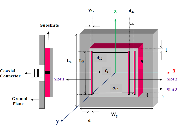 | Figure 1. Geometry of proposed slot-loaded square microstrip patch antenna. Detailed information and constitutive parameters are: Lg = 40 mm, Wg = 40 mm, Ls = 28 mm, Ws = 1 mm, d12 = 24 mm, d13 = 26 mm, d23 = 1 mm, d = 1 mm, l = 1 mm, h = 1.5 mm, = 2 and feed position fp: (x, y) = (0, - 7.5 mm) considering origin at the centre of the patch |
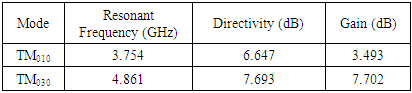
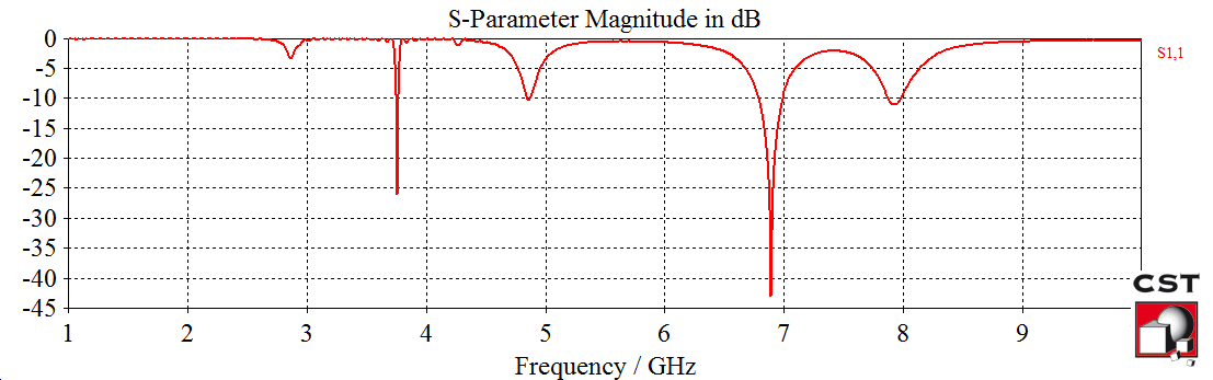 | Figure 2. S-parameter performance of the proposed square microstrip patch antenna, TM010 mode at 3.754 GHz and TM0δ0 mode at 4.861 GHz |
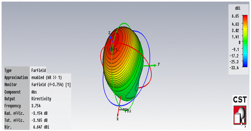 | Figure 3. Three dimensional radiation pattern of TM010 mode at 3.754 GHz |
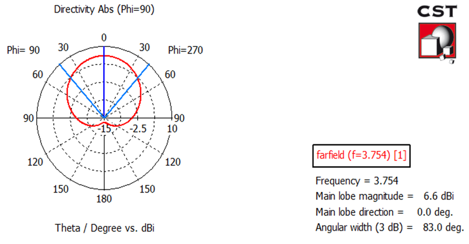 | Figure 4. Polar plot of TM010 mode at 3.754 GHz |
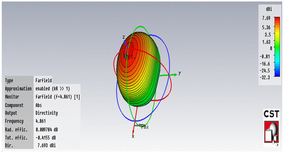 | Figure 5. Three dimensional radiation pattern of TM0δ0 mode at 4.861 GHz |
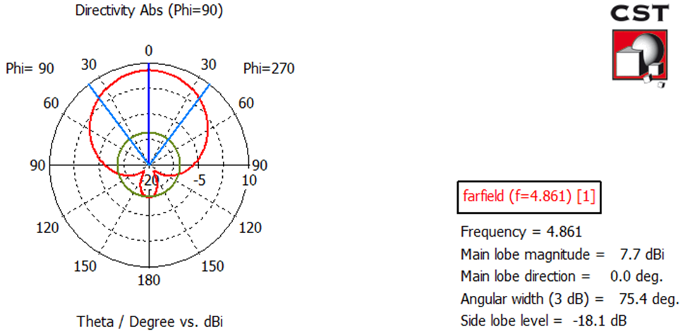 | Figure 6. Polar plot of TM0δ0 mode at 4.861 GHz |
|
3. Theoretical Analysis of Loading Slots on the Patch
- The frequency of operation of the patch antenna is determined by the length L. The center frequency will be approximately given by [34],
 | (1) |
 and the permittivity of the substrate,
  and
and 
 of light so the center frequency of the proposed antenna can be calculated as follows:
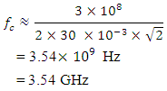 Owing to loading three parallel slots in the proposed antenna it operates at two separate frequencies at 3.754 GHz and 4.861 GHz. The effect of slot on the patch can be analyzed using the duality relationship between the dipole and the slot. The Babinet’s principle [33] of optics is used to derive the property that the radiation pattern of a slot antenna resembles that of a complimentary metallic strip dipole. Babinet’s principle states that (in optics) that when a field behind a screen with an opening is added to the field of a complementary structure (that is a shape covering the screen hole), then the sum is equal to the field where there is no screen. In the proposed antenna the patch is fed by co-axial cable. Since the slot is thin, the voltage can be sinusoidal with zero voltage across the ends of slot. In this case the voltage across the slot is given as [35]
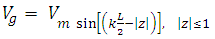 | (2) |
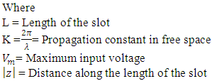 The current distribution of long dipole given as follows [35]
 | (3) |
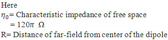
 The total electric field at the far-field point from the antenna is given by [35]
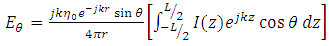 | (4) |
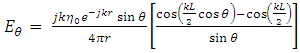 | (5) |
 The Poynting vector can be written as [36]
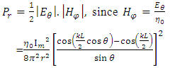 | (6) |
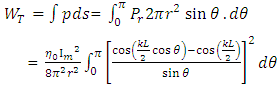 | (7) |
 | (8) |
 | (9) |
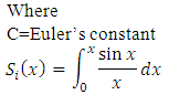 And
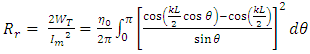
And 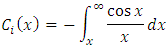 The input impedance of the dipole or slot is given by [35]
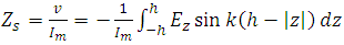 | (10) |
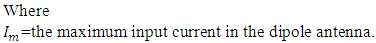
 the electric field along the z-direction.
4. Antenna Feed
- The structure is fed by coaxial probes. The reason behind using this feeding technique is that is the feed can be placed at any desired location inside the patch in order to match with its input impedance (i.e. 50 Ω). Besides, coaxial probe provides low spurious radiation. As seen from Figure 1, the inner conductor of the coaxial connector extends through the dielectric and is soldered to the radiating patch, while the outer conductor is connected to the ground plane. The radius of the inner conductor is 0.3 mm and the radius of outer conductor is 1.2 mm.Selection of the suitable feed location is a dilemma for dual band operation. Because the radiation pattern regularity is influenced by the symmetry of the feeds. A better procedure (when slot case) can be found for probe feed location using modal matching technique following [30]. But in case of our proposed design, the ‘l’ slot will make all these procedures much complex and obviously time consuming. Therefore simulation based iterative process is used by segmenting proposed antenna to choose the suitable feed location. Thus the feed is located at fp: (x, y) = (0, - 7.5 mm) considering origin at the centre of the patch.
5. Dual Band & Frequency Shifting Operation
- The resonant behavior of the slot loaded patch antenna can be explained by initiating from the cavity model description of an unslotted rectangular patch and from cavity perturbation theory. According to cavity model, the first three modes that can be excited in the cavity are usually denoted by TM010, TM020 and TM030. These modes correspond to longitudinal currents distributed on the patch which have nulls at the radiating edges. The TM010 is the most used in practical applications since the TM020 mode has a broadside-null radiation pattern and the TM030 produces grating lobes. While three slots loaded in proposed antenna then the resonant behavior is discussed by cavity perturbation theory. In proportion to cavity perturbation theory, when a resonant cavity is perturbed, i.e. when a foreign object with distinct material properties is introduced into the cavity or when a general shape of the cavity is changed, electromagnetic fields inside the cavity change consequently. The underlying assumption of cavity perturbation theory is that electromagnetic fields inside the cavity after the change differ by a very small amount from the fields before the change. But the change in cavity causes significant change in resonant frequency. The corresponding change in resonant frequency can be approximated as (11) [37]:
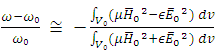 | (11) |
 is the resonant frequency of the original cavity and
  is the resonant frequency of the perturbed cavity,
 represent the magnetic and electric field of the original cavity correspondingly,
  are original permeability and permittivity respectively.Equation (11) can be written in terms of stored energy as follows [37]:
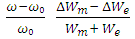 | (12) |
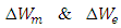 are the changes in the stored magnetic energy and electric energy respectively, after perturbation and
  is the total stored energy in the cavity.Due to etching three narrow slots near radiating edges of proposed antenna, the currents of TM030 resonant frequency circulate around the slots and become similar to the TM010 mode. Thus the slots also modify three lobe shape of TM030 mode to regular behavior. But they do not perturb TM010 mode significantly. The amount of perturbation on excited mode in loaded slot antenna does not have close form formula to calculate, but there is a relationship between two perturbed frequencies (TM010 and TM030) as given in equation (13) [28].
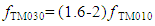 | (13) |
6. Conclusions
- A design of dual band single feed microstrip patch antenna has been proposed and described. The new geometry of the patch has verified to be a high directive and dual band element. This is particularly important for radar systems where directional characteristics, narrow bandwidth are often demanded to determine the range, altitude, direction, or speed of objects. It can also be applied to satellite systems where two channels are needed to provide communication links between various points on Earth. Here, antenna size (30 mm × 30 mm) is reduced compared to the conventional dual-band antenna design. The results show satisfactory radiation pattern, gain & directivity in both frequencies. As a result the proposed antenna is attractive for radar and satellite systems.