-
Paper Information
- Next Paper
- Paper Submission
-
Journal Information
- About This Journal
- Editorial Board
- Current Issue
- Archive
- Author Guidelines
- Contact Us
Electrical and Electronic Engineering
p-ISSN: 2162-9455 e-ISSN: 2162-8459
2016; 6(1): 1-5
doi:10.5923/j.eee.20160601.01

Analysis of Vanadium Redox Flow Battery Cell with Superconducting Charging System for Solar Energy
 Abstract
 Reference
 Full-Text PDF
 Full-text HTML
Andy Kyung-Yong Yoon1, Heung Sik Noh2, Yong Soo Yoon3
1Yonsei University, Dept. of Electrical and Electronics Engineering, Korea
2Hyupsung University, Dept. of Computer Engineering, Korea
3Shin Ansan University, Dept. of Electrical Engineering, Korea
Correspondence to: Yong Soo Yoon, Shin Ansan University, Dept. of Electrical Engineering, Korea.
| Email: |  |
Copyright © 2016 Scientific & Academic Publishing. All Rights Reserved.
This work is licensed under the Creative Commons Attribution International License (CC BY).
http://creativecommons.org/licenses/by/4.0/

This paper describes the analysis of a vanadium redox flow battery (VRB) cell with superconducting magnet energy storage for solar generation system. A VRB is a type of rechargeable battery where recharge ability is provided by two vanadium redox couples, dissolved in liquids contained within the system and most commonly separated by a membrane. In spite of the large capacity support, the majority of development works has focused on stationary application due to the relatively low energy density of VRB [1, 2]. A superconducting charging system (SCS) operate in cryogenic temperature by a cryostat containing liquid helium or nitrogen. The energy stored in the coil and very quick response with high power peaks can be obtained. In addition, SCS provides high efficiency, since the superconducting coil has virtually without Joule losses. Due to low energy density of VRB, it’s not easy to be applied to the Energy Storage System (ESS) which is required quick response time. This paper focuses design and analysis of combined two technologies of electricity storage in order to study the feasibility of very efficient ESS which has quick response time and large capacity simultaneously. This ESS concept will be designed for solar power generation system connected to the grid or independent system respectively.
Keywords: Vanadium redox flow, Superconducting magnetic, Solar PV, Energy storage, Battery
Cite this paper: Andy Kyung-Yong Yoon, Heung Sik Noh, Yong Soo Yoon, Analysis of Vanadium Redox Flow Battery Cell with Superconducting Charging System for Solar Energy, Electrical and Electronic Engineering, Vol. 6 No. 1, 2016, pp. 1-5. doi: 10.5923/j.eee.20160601.01.
Article Outline
1. Introduction
- As fossil fuel resources gradually drained and concerns about global warming increases, focus on renewable energies, such as wind power and solar energy, are increasingly being introduce as alternative energy sources on a global scale toward a low-carbon society. In the next-generation power system that can replace the large power generation sources with energy storage systems have become indispensable. There are many types of energy storages, in particular a VRF battery which is appropriated for large scale energy storage and SMES which is appropriated for quick response time and high density. The energy storage system is a vital element in order to store the energy on the off-grid status, or emergency energy source against sudden blackout status. But most of large-scale ESS cannot start in a second, therefore, there is needed something to fill up the time for second to minutes. Consequently, SMES and VRB are adopted to study the feasibility. SMES should be adopted as fill up the switching time to long discharging, and VRB should be adopted as main energy source. The design is assumed for many situations that will be come up in everywhere.
2. Concept of Energy Storage Technologies
2.1. VRB
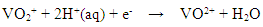
- The VRF battery is a galvanic cell that uses ions dissolved, usually in an acidic solvent (e.g. sulphuric acid), as electrolytes. So the energy is stored in fluids. The redox flow system consists of a reaction unit, reservoirs containing the fluids, and pumps as well as tubes in order to connect the cell with the reservoirs [1].Reduction:
 Oxidation:
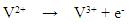 Redox:
 The cell is separated by an ion-exchange membrane permeable for H3O+ Ions but not for metal-ions. The reservoir size can be adapted to the energy which has to be stored. When the system is fully charged, one reservoir contains V2+ ions whereas the other reservoir contains VO2+ ions. Both are dissolved in battery acid. During discharge the ions react as follows:Since vanadium is used in both half-cell, the cell is not affected by cross-over effect. Therefore the vanadium battery has a very long lifetime [3].
2.2. SCS
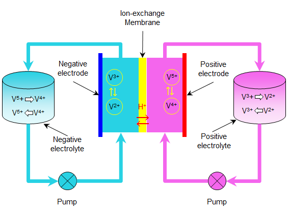
- A SCS stores energy in a magnetic field in a coil of superconducting material. This is similar to capacitors in its ability to response extremely fast [4], but it is limited by the total energy capacity. SCS consists of three major components: the coil, the power conditioning system (PCS), and a cooling system [5]. The idea is to store energy in the form of an electromagnetic field surrounding the coil, which is made of superconductor [2]. The PCS is the interface between the superconducting coil and the power system. It task is to convert alternating current (AC) into direct current (DC) and vice versa since the coil is only capable of storing and releasing the energy in the form of DC [4].
 | Figure 1. Concept of VRB |
 | Figure 2. Concept of SMES |
3. Comparative Analysis of Storage Technologies
3.1. Comparison of Storage Technologies
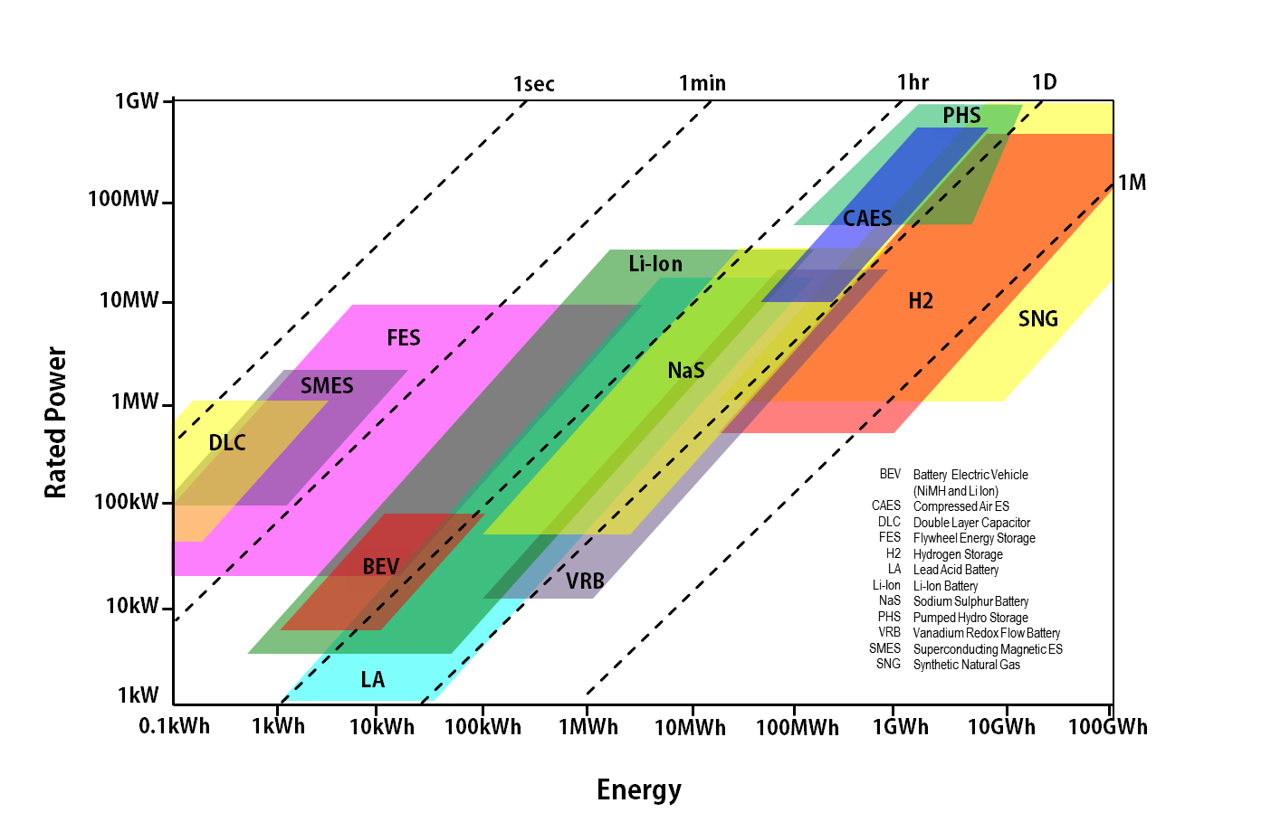
- The rapidly changing field of energy storage covers a wide range of technologies, each with specific technical characteristics. The overview of various electrical energy storage technologies are shown in Fig. 3 [6]. In this double-logarithmic chart the rated power (W) is plotted against the energy content (Wh) of energy storage systems. The nominal discharge time at rated power can also be seen, covering a range from seconds to months [6]. Fig. 3 comprises not only the application areas of today’s ESS systems but also the predicted range in future applications. Not all ESS systems are commercially available in the range shown as Fig, but all are expected to become important. Most of the technologies could be implemented with even larger power output and energy capacity, as all systems have a modular design, or could at least be double. If a large power range or higher energy capacity is not realized, it will be mainly for economic reasons [6].On the basis of Fig. 3 technologies can be categorized as being suitable for applications: at first, short discharge time, this covers seconds to 1 minute as like DLC, SMES (same as SCS), and FES. The energy-to-power ratio is less than 1, also activation response times less than second. At second, medium discharge time, this covers minutes to hours as like FES, Li-ion, LA, and NaS batteries. The technical features of the different electrochemical techniques are relatively similar. Typical discharge times are up to several hours, with an energy-to-power ratio of between 1 and 10. At third, long discharge time, this covers days to months as like H2 and SNG. For these ESS systems the energy-to-power ration is considerably greater than 10.
 | Figure 3. Comparison of power density and energy density of technologies |
3.2. Parameter Determination of the VRB with SMES System
- As shown in Fig. 3, VRB, PHS, and CAES are situated between storage systems for medium and long discharge times. In order to compose the practical energy feeding system against sudden blackout or be an independent ESS system, these technologies should be combined with binding the best in each of them. In this system, SCS can be covered second to minutes at first respond, and VRB covers all activation after a minute. A PV panel’s capacity is 250W, PV operation time estimate 4 h/day. It is concluded that, energy stored energy of a PV panel is 9 kJ/h. In order to supply energy to 10 MW power grids for 10 hours, required energy is 36 GJ, and to meet demand, 10000 PV panels required as well. The point of simulation is that the charging of VRB will be performed in 60 s, and discharging of VRB will be started after 120 s. But VRB cannot be switched to activation mode in a second, what is the reason why, SCS will covers the switching out time during the preparing activation of VRB. Demand and simulation parameter were determined, the equation is as follows.
 | (1) |
 | (2) |
 | (3) |
 | (4) |
4. Design and Analysis
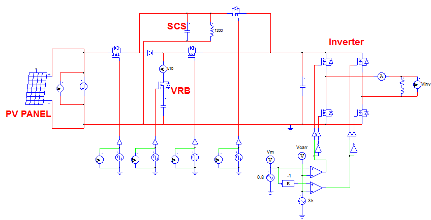
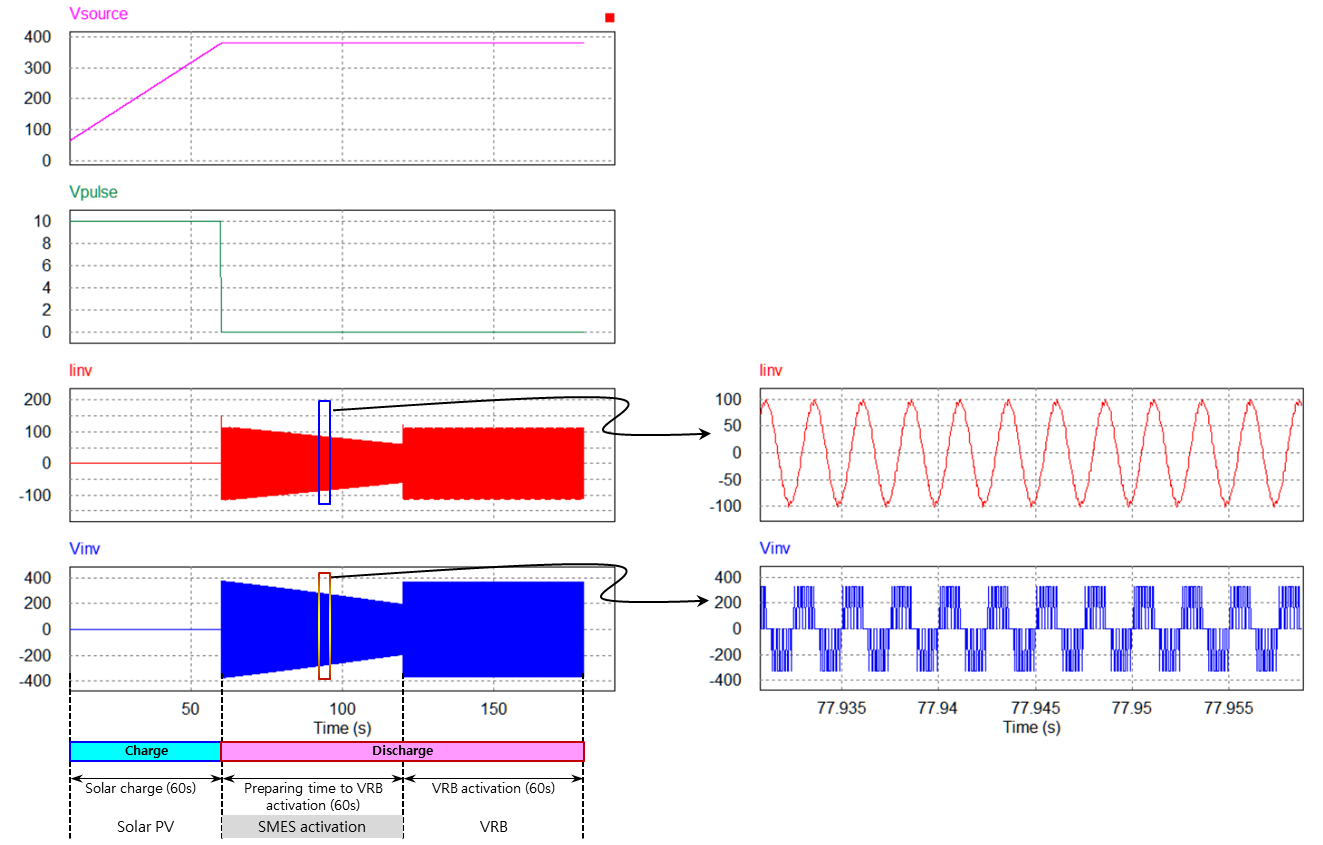
- For this practical ESS system, the SMES and VRB are combined. As shown in the Fig. 3, SCS covers second to minutes at first respond, and VRB covers minutes to hours. This new ideal ESS will cover uninterruptable power function or on-grid or independent ESS connected with solar PV system as the energy source. Fig. 4 shows the ESS schematic, which is combined by SMES and VRB. Fig. 5 shows the simulation results by using PSIM. After 90 s, the output peak voltage and peak current are about 100 V and 300 A, respectively. It is concluded that rms power is about 15 kW. According to the simulation result, first 60 s is an energy storing time, simultaneously the ESS is put on standby again the blackout. In case of sudden blackout, VRB cannot start activate in a second due to the reason why as shown in Fig. 3, whereupon SCS covers the first blackout second to minutes during the time for preparing VRB activation.
 | Figure 4. Schematic diagram of the system |
 | Figure 5. Simulation result of the VRB with SMES system |
5. Conclusions
- The significance of the analysis is feasibility study of two type energy storages combination. As described in previous section, every battery has its own characteristics. Therefore, two or more technologies should be combined to develop applicative ESS or better. This study is trial analysis and simulation which is combined SMES and VRB. Further, PV solar panel is applied as an energy source. Also VRB is adopted to keep the long covering time for 10 h. Total capacity and number of panel are also based on the capacity of VRB. Throughout this paper, possibilities of combination between different energy storages were confirmed, and define the technical standard how calculate and design the capacity, time, and systems.
ACKNOWLEDGMENTS
- This research was supported by Basic Science Research Program through the National Research Foundation of Korea (NRF) funded by the Ministry of Education (2011-0009232).