-
Paper Information
- Paper Submission
-
Journal Information
- About This Journal
- Editorial Board
- Current Issue
- Archive
- Author Guidelines
- Contact Us
Electrical and Electronic Engineering
p-ISSN: 2162-9455 e-ISSN: 2162-8459
2014; 4(4): 63-72
doi:10.5923/j.eee.20140404.01
Design of Substrate Integerated Waveguide Bandpass Filter Based on Metamaterials CSRRs
 Abstract
 Reference
 Full-Text PDF
 Full-text HTML
Ahmed Rhbanou1, Seddik Bri2, Mohamed Sabbane
1Department of Mathematics, FSM, Moulay Ismail University, Meknes, Morocco
2MIN, Electrical Engineering Department, ESTM, Moulay Ismail University, Meknes, Morocco
Correspondence to: Ahmed Rhbanou, Department of Mathematics, FSM, Moulay Ismail University, Meknes, Morocco.
| Email: |  |
Copyright © 2014 Scientific & Academic Publishing. All Rights Reserved.
This article presents a band-pass Substrate Integrated Waveguide (SIW) filter based on Complementary Split Ring Resonators (CSRRs). By etching Square Complimentary Split Ring Resonators on the surface of the substrate integrated waveguide. The bandpass filter is treated by two methods. The first method concerns the use of three square single ring CSRRs cells are etched in the top plane of the SIW, the simulated results of this filter have shown that the passband is from 7.267 GHz to 9.933 GHz, while the insertion loss is -1.11 dB within 31% bandwidth around 8.6 GHz and input return loss in the passband is better than -8.91 dB. The second method concerns the use of three square double rings CSRRs cells are etched on the top plane of the SIW, the simulated results of this filter have shown that the passband is from 7.34 GHz to 9 GHz, while the insertion loss is -0.47 dB within 20.31% bandwidth around 8.17 GHz and the return loss in the passband is better than -15 dB. All the structures are designed on a single substrate of RT / Duroid 5880 permittivity 2.2. The compatibility with planar circuits is provided via a specific microstrip transition (microstrip tapered transitions).
Keywords: Rectangular Waveguide, Substrate Integrated Waveguide, Microwave Filters, Transition, SIW-Microstrip Technology, Complementary Split Ring Resonators, Band-pass
Cite this paper: Ahmed Rhbanou, Seddik Bri, Mohamed Sabbane, Design of Substrate Integerated Waveguide Bandpass Filter Based on Metamaterials CSRRs, Electrical and Electronic Engineering, Vol. 4 No. 4, 2014, pp. 63-72. doi: 10.5923/j.eee.20140404.01.
Article Outline
1. Introduction
- The SIW technology is used in the design of systems transmit and receive microwave, for the researchers and the industrialists who wish to integrate metal waveguides into planar circuits without losses of performances of transmission. The SIW appears as a promising candidate for producing a wide variety of components and devices in the field of the microwaves.The SIW concept associates the use of planar technology microstrip and the functioning of cavities in which are going to exist volume modes [1]. Technically, cavities are included in the substratum and are delimited for the upper and lower faces by the metal plane and for the side faces by rows of metallic holes. This vias have a diameter and spacing small to appear as electric walls [2].However, the SIW has been applied successfully to the conception of planar compact components for the microwave and millimeter wave applications. Such as couplers [3, 4] and filters [5-8], the advantage of this structure is to have a better quality factor and good compatibility.On the other, the metamaterials have been one of the popular areas of research in the field of microwaves in the recent past, such that the Split Ring Resonators (SRR) who may exhibit negative permeability and permittivity and hence negative refractive index [9-12]. The Complementary Split Ring Resonators (CSRR) is introduced for big use in structures planar [13].The CSRR structure is achieved by etching SRR in the background, which can also realize resonance effect and has found great application in the design of wideband bandpass filter [14-20].In this paper, the resonant properties of CSRR are carefully studied, and the rules of the change of resonant frequency are obtained. The bandpass filter is designed based on the characteristic of CSRR band-stop and characteristic of SIW high-pass. The finite element method (FEM) based on a commercial software package “HFSS” is used for simulations. The results obtained by HFSS simulation are compared and discussed with the results in [20].
2. Design of the SIW Technology and the Transitions
- A substrate integrated waveguide (SIW) is made of metallic via-hole arrays in the substrate between top and bottom metal layers replacing the two metal sidewalls are shown in Figure 1.
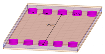 | Figure 1. SIW Guide |
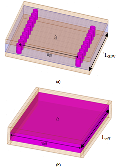 | Figure 2. (a) SIW Guide (b) Equivalent rectangular waveguide |
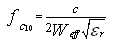 | (1) |
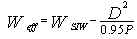 | (2) |
 | (3) |
 | Figure 3. SIW Guide with tapered transitions |
3. Complementary Split Ring Resonators «CSRR »
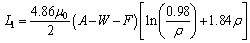
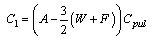
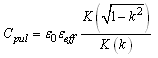
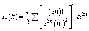
- The electromagnetic properties of SRRs have been already analysed in [10-13]. This analysis shows that SRRs behave as an LC resonator.Split Ring Resonator (SRR) is a well known sub-wavelength metamaterial structure that exhibits negative values of permeability over a narrow frequency band around it resonance frequency. The resonant frequency is determined from the geometrical parameters of SRR. The SRR can have different types of structures (square, circular, Omega ...) with single ring, double ring or multiple ring SRR cells.The Complementary Split Ring Resonator CSRR is the complementary of SRR [12]. The CSRR the rings are etched on a metallic surface and its electric and magnetic properties are interchanged with respect to the SRR. Figure 4 shows the difference between the SRR and the CSRR. In fact, all the conductive part (rings) and the dielectric part of the SRR are respectively replaced by the dielectric and conductive plan of a substrate in the CSRR.
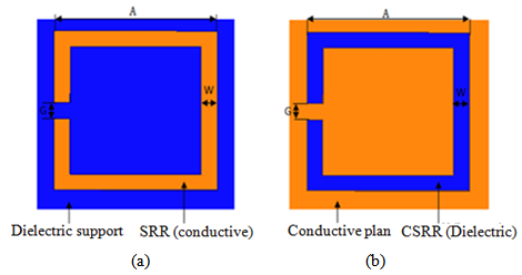 | Figure 4. (a) Square-shaped single-ring SRR (b) square-shaped single-ring CSRR |
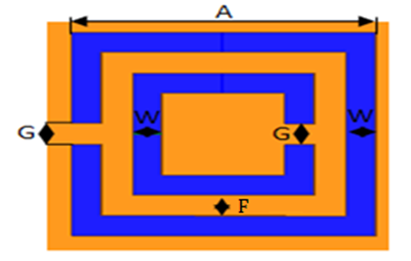 | Figure 5. Geometry square CSRR of the double rings |
 | (4) |
 | (5) |
 | (6) |
 | (7) |
 | (8) |
 | (9) |
 | (10) |
 | (11) |
 | (12) |
 | (13) |
4. Results
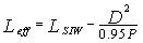
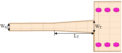
- In this work, all the structures are designed on a single substrate of RT / Duroid 5880 permittivity εr =2.2 and height h = 0.254 mm.Generally to determine the parameters of SIW guide, designed in the X-band [8.2-12.4] GHz from a conventional wave guide with dimensions a= 22.86 mm and b= 10.16 mm, using the formulas given by equations 1, 2 and 3. With the diameter of the metallic via D = 0.8 mm and the period of the vias P = 1.6 mm. Following this approach, the distance between the rows of the centres of via is WSIW =16 mm and the length of SIW guide is LSIW =Leff =80 because does not bring significant change in the propagation phenomenon.A microstrip transition (taper) is used to interconnect SIW to the planar transmission lines. There is a tapered section which is used to match the impedance between a 50Ω microstrip line and the SIW. The 50Ω microstrip line, in which the dominant mode is quasi-TEM, can excite well the dominant mode TE10 of the SIW, as their electric field distributions are approximate in the profile of the structure.The parameters (the width WM) of the microstrip line and (the width WT and the length LT) the transitions are determined from several formulas given in [2, 4].The dimensions retained are WM=0.8 mm, WT =5.2 mm and LT =14 mm.A schematic view of a SIW with two tapered transitions is shown in Figure 6.
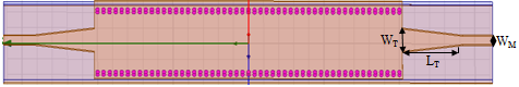 | Figure 6. SIW with two tapered transitions |
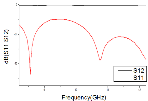 | Figure 7. Transmission coefficient S12 and reflection coefficient S11 of SIW with two tapered transitions |
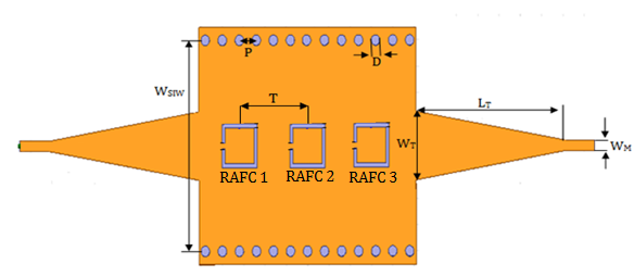
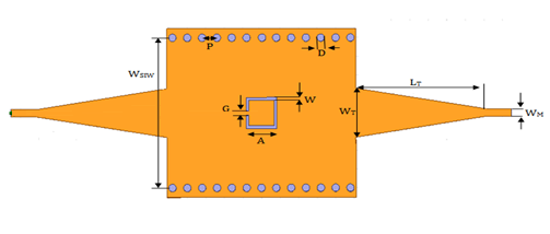 | Figure 8. SIW guide with square single ring CSRR |
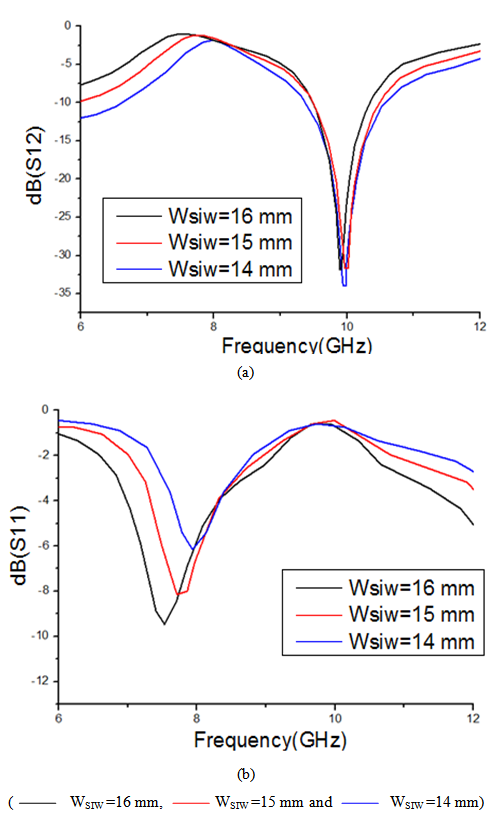
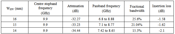
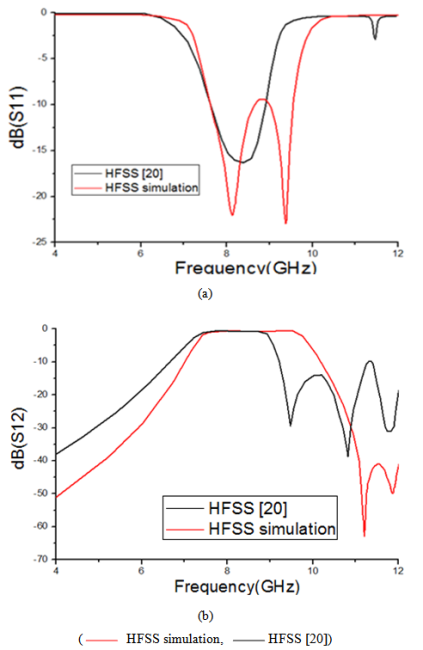
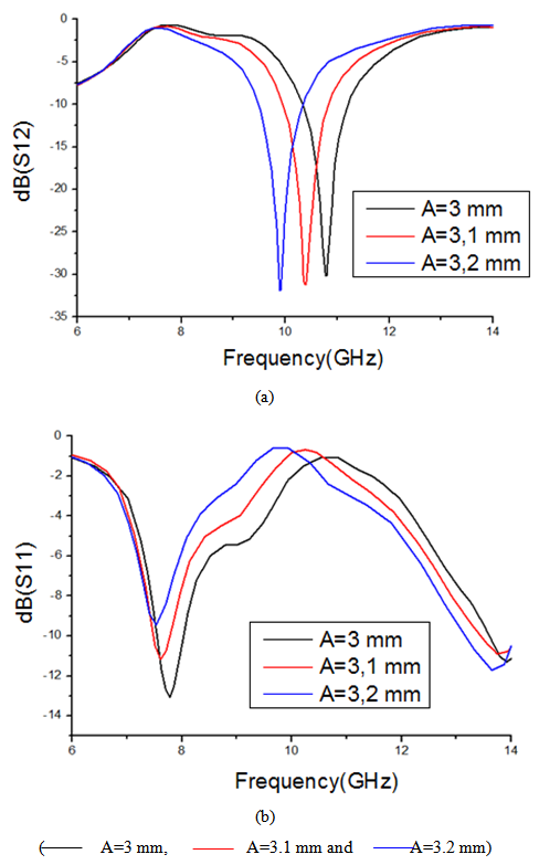 | Figure 9. Frequency response of the SIW guide with square single ring CSRR (a) Transmission coefficient S12 as a function of frequency (b) Reflection coefficient S11 as a function of frequency |
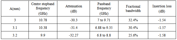
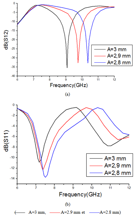
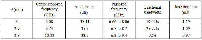
 | Figure 10. Frequency response of the SIW guide with square single ring CSRR (a) Transmission coefficient S12 as a function of frequency (b) Reflection coefficient S11 as a function of frequency |
|
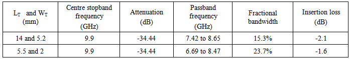
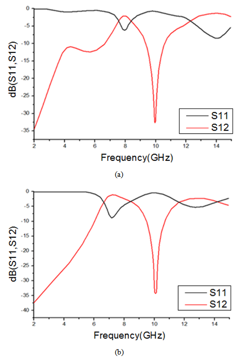 | Figure 11. (a) Frequency response of the structure (SIW guide with square single ring CSRR) with LT=14 mm and WT =5.2 mm (b) Frequency response of the structure (SIW guide with square single ring CSRR) with LT=5.5 mm and WT =2 mm |
|
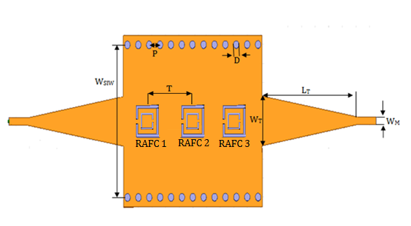
 | Figure 12. SIW bandpass filter based of three square single ring CSRRs cells |
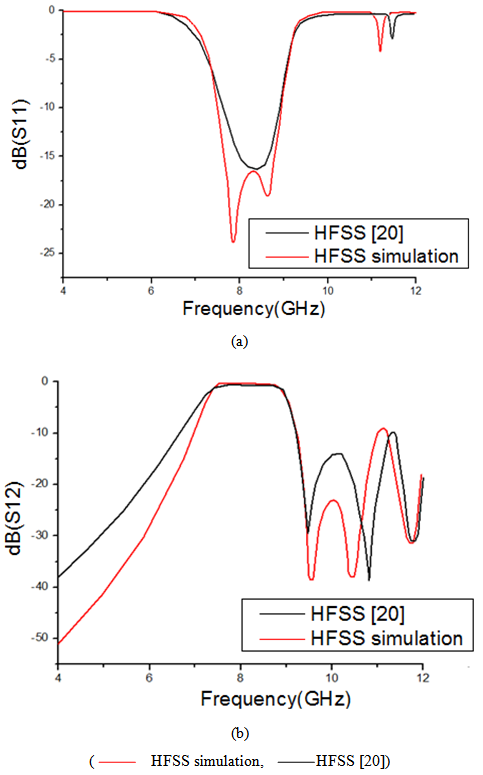
 | Figure 13. Frequency response of SIW bandpass filter based of three square single ring CSRRs cells (a) Reflection coefficient S11 as a function of frequency (b) Transmission coefficient S12 as a function of frequency |
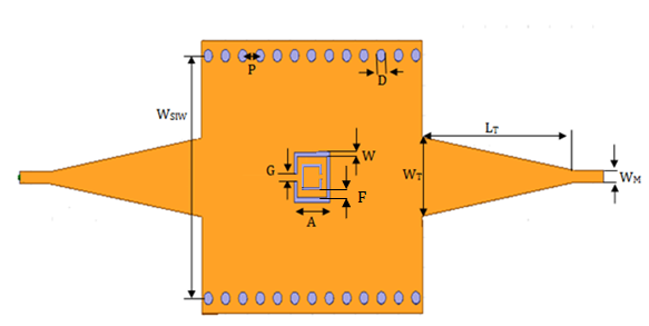 | Figure 14. SIW guide with square double rings CSRR |
 | Figure 15. Frequency response of the SIW guide with square double ring CSRR (a) Transmission coefficient S12 as a function of frequency (b) Reflection coefficient S11 as a function of frequency |
|
 | Figure 16. SIW bandpass filter based of three square double ring CSRRs cells |
 | Figure 17. Frequency response of SIW filter based of three square double ring CSRRs cells (a) Reflection coefficient S11 as a function of frequency (b) Transmission coefficient S12 as a function of frequency |
5. Conclusions
- In this work, two bandpass SIW filter based on Complementary Split Ring Resonators (CSRRs) were presented for X-band applications. Which are designed by two methods, The first method concerns the use of three square single ring CSRRs cells are etched in the top plane of the SIW, the simulated results of this filter have shown that the passband is from 7.267 GHz to 9.933 GHz, while the insertion loss is -1.11 dB within 31% bandwidth around 8.6 GHz and input return loss in the passband is better than -8.91 dB. The second method concerns the use of three square double rings CSRRs cells are etched on the top plane of the SIW, the simulated results of this filter have shown that the passband is from 7.34 GHz to 9 GHz, while the insertion loss is -0.47 dB within 20.31% bandwidth around 8.17 GHz and the return loss in the passband is better than -15 dB.These filters are easy for integration with other planar circuit compared by using conventional waveguide. The design method is discussed; the results from our analysis are in good agreement with previous research done on this topic. These bandpass SIW filters based on Complementary Split Ring Resonators (CSRRs) are suitable for practical applications.
References
| [1] | Bouchra Rahali and Mohammed Feham, “Design of K-Band substrate integrated waveguide coupler, circulator and power divider,” International Journal of Information and Electronics Engineering, Vol. 4, No. 1, pp. 47-53, January 2014. |
| [2] | Hemendra Kumar, Ruchira Jadhav and Sulabha Ranade, “A review on substrate integrated waveguide and its microstrip interconnect,” Journal of Electronics and Communication Engineering, Vol. 3, pp. 36-40, September- October 2012. |
| [3] | B. H. Ahmad, Siti Sabariah Sabri and A. R. Othman, “Design of a compact X-Band substrate integrated waveguide directional coupler,” International Journal of Engineering & Technology, Vol. 5, No. 2, pp. 1905-1911, April-May 2013. |
| [4] | K. Nouri, M. Feham, Mehdi Damou and Tayeb Habib Chawki Bouazza, “Design of substrate integrated waveguide micro-wave planar directional coupler,” International Journal of Scientific & Engineering Research, Vol. 5, pp. 1239-1242, February 2014. |
| [5] | K. Nouri, K. Haddadi, O. Benzaïm, T. Lasri and M. Feham, “Substrate integrated waveguide (SIW) inductive window band-pass filter based on post-wall irises,” The European Physical Journal Applied Physics, Vol. 53, 2011. |
| [6] | Yongmao Huang, Zhenhai Shao and Lianfu Liu, “A substrate integrated waveguide bandpass filter using novel defected ground structure shape,” Progress In Electromagnetics Research, Vol. 135, pp. 201-213, 2013. |
| [7] | Nouri Keltouma, Feham Mohammed and Adnan Saghir, “Design and characterization of tapered transition and inductive window filter based on Substrate Integrated Waveguide technology (SIW),” International Journal of Computer Science Issues, Vol. 8, No 3, November 2011. |
| [8] | D. Zelenchuk, V. Fusco, “Low insertion loss substrate integrated waveguide quasi-elliptic filters for V-band wireless personal area network applications,” IET Microwaves, Antennas and Propagation, Vol. 5, No. 8, pp. 921-927, 2010. |
| [9] | Ming-feng Wu, Fan-Yi Meng, Qun Wu, Jian Wu, and Joshua Le-Wei Li, “SRRs’ Artificial Magnetic Metamaterials Modeling Using Transmission Line Theory,” Progress in Electromagnetics Research Symposium Online, Vol. 1, No. 5, pp. 630-633, 2005. |
| [10] | Vidyalakshmi. M.R and Dr.S.Raghavan, “Comparison of optimization techniques for square split ring resonator,” International Journal of Microwave and Optical Technology, Vol. 5, No. 5, September 2010. |
| [11] | F. Martı́n, J. Bonache, F. Falcone, M. Sorolla and R. Marqués, “Split ring resonator-based left-handed coplanar waveguide,” Applied Physics Letters, Vol. 83, No. 22, December 2003. |
| [12] | J. Bonache, F. Martin, R.M. Sillero, F. Falcone, T. Lopetegi, M.A.G. Laso, J. Garcia-Garcia, I. Gil, M.F. Portillo, M. Sorolla, “Equivalent-circuit models for split-ring resonators and complementary split-ring resonators coupled to planar transmission lines,” IEEE Transactions on Microwave Theory and Techniques, Vol. 53, No. 4, April 2005. |
| [13] | Gerard Sisó, Marta Gil, Manuel Aranda, Jordi Bonache, Ferran Martín, “Miniaturization of planar microwave devices by means of complementary spiral resonators (CSRs): Design of quadrature phase shifters,” Radioengineering, Vol. 18, No. 2, pp. 144-148, 2009. |
| [14] | X. Lai, Q. Li, P. Y. Qin, B. Wu and C.-H. Liang, “A novel wideband bandpass filter based on complementary split-ring resonator,” Progress In Electromagnetics Research C, Vol. 1, pp. 177-184, 2008. |
| [15] | Mohammed Bait-Suwailam, “Miniaturized Bandstop Filters Using Slotted-Complementary Resonators,” International Journal of Digital Information and Wireless Communications (IJDIWC), Vol. 4, No. 3, pp. 401-407, 2014. |
| [16] | R. S. Kshetrimayum, S. Kallapudi and S. S. Karthikeyan, “Stop band characteristics for periodic patterns of CSRRs in the ground plane,” International Journal of Microwave and Optical Technology, Vol. 2, No. 3, July 2007. |
| [17] | R. S. Kshetrimayum, S. Kallapudi and S. S. Karthikeyan, “Stop Band Characteristics for Periodic Patterns of CSRRs in the Ground Plane and its Applications in Harmonic Suppression of Band Pass Filters,” International Journal of Microwave and Optical Technology, Vol. 3, No. 2, April 2008. |
| [18] | Chao Li, K. Y. Liu, and Fang Li, “A Microstrip Highpass Filter with Complementary Split Ring Resonators,” Progress in Electromagnetics Research Symposium Online, Vol. 3, No. 5, pp. 583-586, 2007. |
| [19] | S. Kareemulla, M. Praveen Kumar and Dr.DN. Sri Ram Kumar, “A novel SIW BPF based on circular complimentary split ring resonators for millimeter wave applications,” International Journal of Engineering Science and Technology, Vol. 5, No. 4, April 2013. |
| [20] | Damou Mehdi, Nouri Keltouma, Taybe Habib Chawki Bouazza and Meghnia.Feham, “Design of substrat integerated waveguide bandpass filter of SCRRs in the microstrip line,” International Journal of Engineering Research and General Science, Vol. 2, pp. 302-314, April-May 2014. |