Ayman Nasih Salman Younis
Department of Electrical and Electronics, College of Engineering, University of Thi-Qar, Nasirah, Iraq
Correspondence to: Ayman Nasih Salman Younis , Department of Electrical and Electronics, College of Engineering, University of Thi-Qar, Nasirah, Iraq.
| Email: |  |
Copyright © 2014 Scientific & Academic Publishing. All Rights Reserved.
Abstract
This paper focuses on the design of compact planar multiband antennas intended for existing wireless services including GSM 850, GSM 900, DCS 1800, PCS 1900, WLAN and Wi‐MAX for 3:1 VSWR. Because of it has two-dimensional structure, the prototype is printed on RF4 substrate with 0.8mm thickness with overall dimensions of this antenna is 112x45mm.The simulation performed in this paper used a CST Microwave Studio to optimally design the antenna. The current study simulated the antenna parameters including reflection coefficient, radiation characteristics, gain, and radiation efficiency to validate the proposed antenna.
Keywords:
Multi band antenna, Mobile handset, Loop antenna
Cite this paper: Ayman Nasih Salman Younis , Compact Loop Atenna for Multi-Bands Mobile Hndset Applications, Electrical and Electronic Engineering, Vol. 4 No. 3, 2014, pp. 58-61. doi: 10.5923/j.eee.20140403.03.
1. Introduction
The demand for new technology in mobile handset device made the engineering increase interesting in the resent year. There are many challenges for antenna design for mobile phone applications such as its integration into portable handset device use of conducting materials in the cover, and its must be a thin, light, small and have low energy requirement. There are different antenna forms are adopted for the internal antenna design in the mobile handset applications, such as folded monopole antennas [1], [2] IFA/PIFA [3, 4], printed loop [5], and ceramic antenna [6] and so on. The printed loop antennas have received the widest attention in publications due to their simplicity in analysis and construction, wide bandwidth, ease of controlling higher mode, and self-balance of the current [7-9]. The loop antenna can be designed as a folded inverted conformal antenna (FICA) in several commercial products [10, 11]. Several practical techniques focus on modifications to the main radiator to reduce size and improve impedance matching for specific antennas [12]. Another strategy is depended on elongate the main radiator’s physical length to achieve multiple resonant modes [13]. However, create several radiating branches may occupy more space, hence making the antenna physically larger than the desired volume. This paper present a compact folded loop antenna loop antenna that can afford multiband applications in the mobile systems, including the Global System for Mobile Communications GSM 850 (824-894 MHz), GSM 900 (880–960 MHz), the Digital Cellular System DCS (1720–1880 MHz), the wireless local area network WLAN (2400–2484 MHz), and World Wide Interoperability For Microwave Access (WiMAX) bands (300–370 MHz). It uses traditional loop theory for calculating initial dimensions of antenna structure. Then a series of simulation is done to get optimize dimensions of the printed loop structure based on the requirement for desired bands of operations. The rectangular printed loop antenna is further bended; this will further help in reduction of dimensions of the proposed antenna. Thus, the bending of the printed loop antenna helps in reduction in volume of antenna structure. The proposed design uses two monopole slots in it, to increase the bandwidth of the antenna. Furthermore, the design has many advantages for mobile phone applications, such as low cost, simple structure, compact size, and acceptable radiation efficiency. The design of the proposed antenna is described in the section 2. The simulated results are discussed in Section 3.
2. Antenna Design
Loop antennas can be classified into two categories, electrically small and electrically large. Electrically small antennas are those whose overall length (circumference) is usually less than about one-tenth of a wavelength (C < λ/10). However, electrically large loops are those whose circumference is about a free-space wavelength (C ∼ λ). In general, loop antennas with electrically small circumferences or perimeters have small radiation resistances that are usually smaller than their loss resistances. Thus they are very poor radiators, and they are seldom employed for transmission in radio communication. Because of the current distribution of loop antenna structure depends on the dimensions of the loop, the radiation resistance of the loop can be increased by increasing (electrically) its perimeter and/or the number of turns. In small loop structures the current distributed uniformly and it is valid until the circumference of the loop is less than about 0.2 times of the wavelength (or radius less than 0.03 times of wavelength) [14]. Thus for small loop antenna structure: | (1) |
where I0 is a constant. As the dimensions of the loop increase, the current variations along the circumference of the loop must be taken into account. A better distribution would be to represent the current by a Fourier series [14]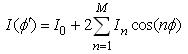 | (2) |
where φ is measured from the feed point of the loop along the circumference. For the proposed antenna, the electrically large loop is used. The loop is used as a printed element for designing of a compact printed loop antenna for laptop applications. The electrically large loop structure has its perimeter equal to 1-wavelength [14]. Thus by deciding an operating frequency, the perimeter of the rectangular loop is obtained. Fig. 1 shows the configuration of the proposed antenna. In order to cover mobile bands applications, the frequency range selected for the simulation lies in between 0-3.7 GHz. However, 2 GHz is selected as operating frequency for deciding the initial dimension of internal compact printed loop. The initial dimension of the loop taken as 45 mm and 12mm. After the simulation of simple rectangular printed loop structure, the loop is folded to obtain other frequency bands. The proposed antenna is composed of a folded rectangular planar radiator and a slotted ground structure formed by two monopole slots to meet the needs for multiband operation and antenna size reduction. The main radiator is printed on the top of a 0.8-mm thick FR4 substrate of size 45x112mm, on the lower portion of the substrate is a 45x100 ground plane. In the slot's design, the slots 1 and 2 have a uniform width 0.5mm but different lengths. The lengths of slot 1 and slot 2 are selected to be S1=25mm (an open-ended monopole slot, 0.17-wavelength at 2.3 GHz) and S2=17mm for lower fundamental frequency 850 MHz respectively. The coupling gap between the feeding strip and coupling strip is selected to have a narrow width of 0.5 mm, which is helpful in obtaining wide bandwidths for the excited resonant modes, especially for the lower band.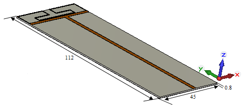 | Figure 1. Prototype proposed antenna |
The designing steps of proposed antenna are explained in following steps:
2.1. Low Frequency (GSM 850/900) Bands
Firstly we designed a simple patch antenna with overall size 112 x 45 x 0,8 mm3 and its patch dimension is 12 x 45 mm2 as shown in Fig. 2. This simple patch antenna is working on low resonant frequency to cover GSM 850/900 bands. The three parameters L, W, and S are defined the simple loop antenna design, where W is width of loop on front patch, H is length of folded loop, and S is feed position the parameters are optimized to achieve the desire resonance frequencies. 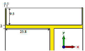 | Figure 2. Simple loop antenna with (mm) dimensions |
2.2. High Frequency (DCS/PCS/ISM/WiMAX) Bands
For modifying structure Fig. 3, the loop pattern is meandered and folded to increase electric length and support the meandered loop occupies less size, a tuning strip line from C to M is inserted into the loop. The total length of the folded and meandered loop strip from C to D is about 20 mm, from D to E is 4.8mm, from E to F is 11.5mm, from F to G is 3mm, and, from G to O is 28mm as shown in Fig. 2(a). This arrange generates four resonance modes can be used for DCS/PCS/ISM/WiMAX band.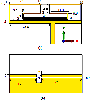 | Figure 3. Geometry and dimensions (mm) of the proposed antenna (a) Front (b) Back |
To broaden the impedance bandwidth, two uniform slots have o.5mm width and 17mm, 25mm lengths with a matching 3mmx3mm square slot as shown in Fig.3 (b), is placed on the backside. Finally, the feed line is connected to a 50 ohm.
3. Results and Discussions
The proposed antenna design was optimized and analyzed by using CST Microwave Studio based on Finite Difference Time Domain method (FDTD). Fig. 4 shows that the resonant frequencies of the antenna structure are (830-922MHz) for the GSM 850/900 band, and (1650-1880MHz) DCS 1800 band, (2.1-2.9 GHz) for ISM WLAN band and (3-3.7GHz) for WiMAX applications. The 6 dB bandwidths for GSM 900, DCS 1800, 2.4 GHz WLAN and 3.5GHz WiMAX are 172MHz and 280MHz, 600MHz and 600MHz respectively. 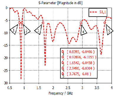 | Figure 4. The simulated return losses of the proposed antenna |
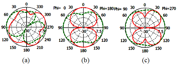
The simulated radiation pattern of the  , and
, and  of the proposed antenna structures are shown in Figs. 5-9. The figures plot the simulated radiation patterns for XY-plane, XZ-plane and YZ-plane at 880, 908, 1780, 2430 and 3600 MHz. Finally, the simulated gains and radiation efficiency of GSM band and DCS, PCS, ISM, and WiMAX bands are shown in Fig. 10(a) and Fig. 10 (b) respectively. The simulated gains of GSM band is from 0.56 to 3 dBi while that of DCS, PCS, ISM, and WiMAX bands is from 1 to 3.9 dBi. The simulated radiation efficiency of GSM band is from 55% to 75% while that of DCS, PCS, ISM, and WiMAX bands is from 57% to 80%.
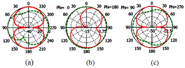 | Figure 5. Simulated radiation pattern of proposed antenna at 880 MHz (a) XY-plane (b) XZ-plane (c) YZ plane |
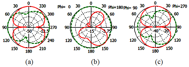 | Figure 6. Simulated radiation pattern of proposed antenna at 908 MHz (a) XY-plane (b) XZ-plane (c) YZ-plane |
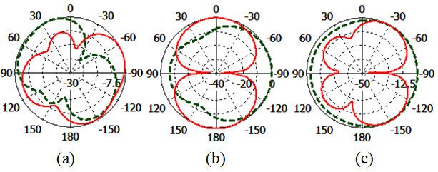 | Figure 7. Simulated radiation pattern of proposed antenna at 1780MHz (a) XY-plane (b) XZ-plane (c) YZ-plane |
 | Figure 8. Simulated radiation pattern of proposed antenna at 2430MHz (a) XY-plane (b) XZ-plane (c) YZ-plane |
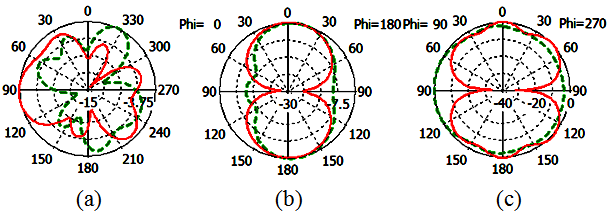 | Figure 9. Simulated radiation pattern of proposed antenna at 3600 MHz (a) XY-plane (b) XZ-plane (c) YZ-plane |
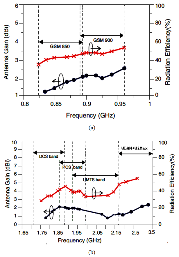 | Figure 10. The simulated gains and radiation efficiency of (a) GSM 850/900 bands and (b) DCS, PCS, ISM, and WiMAX bands |
4. Conclusions
This paper proposes printed loop antennas with low profile and compact size. A prototype of the proposed antenna is designed with 0.8 mm in height and  . By create different current paths for different resonances, the operation frequency bands to cover GSM850/ 900, DCS, PCS, ISM, and WiMAX application bands with bandwidth 18%, 16%, 25%, and 25% respectively. The simulated radiation pattern in X-Z, Y-Z, and X-Y planes at 900MHz, 1780MHz, 2400MHz and 3500MHz have acceptable form for mobile handset applications. The maximum radiation efficiency reaches 58% and the radiation efficiency at lower and upper bands are over 35%.
References
| [1] | Shun-Yun Lin., 2004, Multiband Folded Planar Monopole Antenna for Mobile Handset, IEEE Trans. on Antennas and Propagation, 52(7), 1790-1794. |
| [2] | K. L. Wong and S. C. Chen, 2010, Printed single-strip monopole using a chip inductor for Penta-Band WWAN operation in the mobile phone, IEEE Trans. Antennas Propagation., 58(3), 1011–1014. |
| [3] | C. H. Wu and K. L. Wong, 2009, Ultrawideband PIFA with a capacitive feed for penta-band folder-type mobile phone antenna, IEEE Trans. Antennas Propagation., 57(8), 2461-2464. |
| [4] | K. R. Boyle and P. G. Steeneken, 2007, A five-band reconfigurable PIFA for mobile phones, IEEE Trans. Antennas Propagation., 55(11), 3300–3309. |
| [5] | C. H. Ku, H. W. Liu, and S. Y. Lin, 2010, Folded dual-loop antenna for GSM/DCS/PCS/UMTS mobile handset applications. IEEE Antennas Wireless Propagation. Lett.,9, 998-1011. |
| [6] | David Kearney, Matthias John, and Max J. Ammann, 2011, Miniature Ceramic Dual-PIFA Antenna to Support Band Group 1 UWB Functionality in Mobile Handset, IEEE Antenna and propagation, 59(1), 336-339. |
| [7] | K. L. Wong and C. H. Huang, 2008, Printed loop antenna with a perpendicular feed for penta-band mobile phone application, IEEE Antennas Propagation., 56(7), 2138–2141. |
| [8] | Y. W. Chi and K. L. Wong, 2008, Compact multiband folded loop chip antenna for small-size mobile phone, IEEE Antennas Propagation., 56(12), 3797–3803. |
| [9] | C. H. Ku, H. W. Liu, and S. Y. Lin, 2010, Folded dual-loop antenna for GSM/DCS/PCS/UMTS mobile handset applications, IEEE Antennas Wireless Propagation, 9, pp. 998–1011. |
| [10] | C. Nallo and A. Faraone, 2005, Multiband internal antenna for mobile phones, Electronic Letters, 41(9), 514–515, 2005. |
| [11] | C. Nallo and A. Faraone, 2005, The folded inverted conformal antenna (FICA) for multi-band cellular phones, IEEE Antennas and Propagation. Soc. Int. Symp., (4B), 52–55. |
 Abstract
 Reference
 Full-Text PDF
 Full-text HTML