Ehsan Morad1, Ehsan Rasouli2, Maryam Alasvandi3
1Department of Electrical Engineering, SAMA Technical and Vocational Training College, Islamic Azad University, Ahvaz Branch, Ahvaz, Iran
2Department of Electrical Engineering, Amirkabir University of Technology, Tehran, Iran
3Department of Electrical Engineering, Islamic Azad University, Tehran, Iran
Correspondence to: Ehsan Morad, Department of Electrical Engineering, SAMA Technical and Vocational Training College, Islamic Azad University, Ahvaz Branch, Ahvaz, Iran.
| Email: |  |
Copyright © 2014 Scientific & Academic Publishing. All Rights Reserved.
Abstract
A low-voltage and low-power common gate Gilbert cell down-conversion mixer with high linearity design developed using TSMC 0.18-μm technology is presented in this paper. The mixer is designed to operate at 2.4 GHz with the local oscillator frequency 2.1 GHz and the intermediate frequency 300 MHz. Multiple-gated transistors (MGTR) method was employed to improve linearity in proposed common gate Gilbert cell-based mixer. Simulation results on HSPICE indicate that over 16dBm increase in IIP3 (third-order intermodulation intercept point) after optimization of the mixer. The proposed mixer operates using a supply voltage of 1.8 V, with a power consumption of about 4.32 mW. The noise figure and conversion gain of the mixer are 12.87 dB and 2 dB, respectively.
Keywords:
Common-Gate Mixer, Gilbert Cell, Intermodulation Distortion, Linearity, Multiple Gated Transistors Method
Cite this paper: Ehsan Morad, Ehsan Rasouli, Maryam Alasvandi, High Linearity Common Gate Gilbert Cell Mixer Design Using CMOS 0.18 μm Technology for 2.4 GHz Applications, Electrical and Electronic Engineering, Vol. 4 No. 3, 2014, pp. 52-57. doi: 10.5923/j.eee.20140403.02.
1. Introduction
Advancements in electronics have led into increasing dependence on the science even in daily life where it is hard to find a single day which does not involve at least one instance of using communication and electronic devices. The industrial, scientific, and medical (ISM) band is a suitable one for IC manufacturers as it is free and does not require obtaining permissions. An essential part of any communication device is its transmitter and receiver circuits which contain different blocks, including mixers as extremely important components. Linearity is an important parameter in designing mixers since linearity of the mixer significantly affects linearity in the whole transmitter/receiver system [1-3]. Nonlinearity results in numerous problems including harmonic generation, gain compression, and even order distortions [4, 5]. Different methods have been proposed for improving linearity; however, many of them require complex circuits or consume large amounts of power [5-8]. One technique for improving linearity, which will be described in the present paper, is multiple gated transistors method.
2. Theory Section
In this section, mixer design theory is expressed. The mixer structure is explained in first subsection. Subsection 2 is introduced intermodulation distortion. Finally, common gate double balanced mixer is explained in third subsection.
2.1. Mixer
Band-pass filters of transmitters are often designed at low frequencies due to limitations on quality factor of elements, such as inductors [1].In addition, information-bearing signals received of communication receivers are often detected at low frequencies such as intermediate frequency (IF). Therefore, mixers in receivers shift modulated signals into higher frequencies while high-frequency signals received of receivers are shifted toward IF prior to signal detection. Mixers are classified into two broad categories: down-conversion mixers and up-conversion mixers. The mechanisms involved in frequency shifting function are essentially the same for both up and down conversion mixers. The frequencies are shifted in mixers by multiplying two signals and their harmonic components. Down-conversion mixers have two separate inputs: radio frequency (RF) input and local oscillator (LO) input. The RF input takes the signal which should be shifted to lower frequencies while the LO input receives a properly shaped waveform generated by the oscillator. The IF signal at the output is the result of multiplication of the two signals and their harmonic components [1].
2.2. Intermodulation Distortion
When two signals that have different frequencies are applied in a nonlinear system, the output will contain components which have not input harmonic frequencies. This phenomenon, usually referred to as intermodulation, is the result of mixing or multiplication of the two signals when their sum is raised to a power larger than one. Intermodulation is a problematic effect in RF systems. When a weak signal mixed with two high powered interfering signals face third order nonlinearity, one intermodulation component falls onto the frequency band in use and this will distort the fundamental components. Although this only impacts the amplitude of the signal, however even information contained in the signal phase may be lost since zero crossings are affected as well. The effect cannot be directly calculated using harmonic distortion. Distortion as a result of third order intermodulation between two close interfering signals is of such a great importance that a new parameter has been defined to examine this incident. This parameter, known as third-order intercept point (IP3), is measured using two-tone test. Third-order intercept point (IP3) that is the important performance measure in mixer linearity, is desired to be increase in mixer design [1, 2].
2.3. Common Gate Double Balanced Mixer
A mixer that accommodates a differential LO signal but a single-ended RF signal is called a single balanced mixer. A double balanced mixer operates with both differential LO and RF signals and its active form is similar to Gilbert cell. Double balanced mixers produce less odd order distortion. A typical mixer is composed of three stages: transconductance stage, switching stage, and load stage. In the common gate double balanced mixer shown in Figure 1, the transistors M1, M2, M3 and M4 construct the transconductance stage. Here, M1 and M3 act as current sources. M2 and M4 convert RF voltage to RF current. The capacitors (CB) are used to block DC voltage. The differential pairs M7-M8 and M5-M6 form the switching stage, add the amplified LO signal with different phases, and perform first order cancellation. R1 and R2 are used as resistive loads in the load stage of the mixer. They also convert IF current to IF voltage. The output can be used in single-ended or differential architecture. Differential output not only has a high conversion gain but also provides greater protection against RF signal penetration compared to IF output. Despite these advantages, many mixers require single-ended output since IF SAW (Surface Acoustic Wave) filters, which are usually placed next to mixers often, usually have a single-ended structure [1-3]. | Figure 1. Gilbert cell-based mixer, conventional common gate arrangement [5] |
3. Improved Linearity Using MGTR
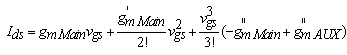
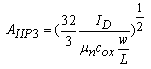
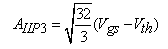
As noted earlier, linearity plays a significant role in RF systems and numerous methods have been proposed to improve linearity. One approach to improve linearity involves application of multiple gated transistors. In this topology, a number of auxiliary transistors are biased at a voltage below threshold level (cut-off) to create linear conditions. Recently, this technique has been employed to improve linearity in low-noise and low-power amplifiers [9-11]. Neglecting the nonlinearity caused by switching transistor, the most important factor contributing to nonlinearity in mixers is the transconductance stage where RF voltage is converted into RF current. In the present paper, MGTR is employed to improve linearity at the transconductance stage of a common gate mixer. Equation (1) expresses input-output relation of nonlinear system that Vgs and ID are input and output of nonlinear system (Transistor of transconductance stage), also gm is transconductance of Transistors in transconductance stage. Relations show that gm” (Second derivative of transconductance) has important role in system non-linearity because it can make non-desired harmonic. The gm” should be decreased to achieve desired linearity. The α1 and α3 are Taylor series coefficients [11, 12]. 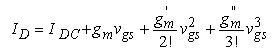 | (1) |
 | (2) |
 | (3) |
 | (4) |
As seen in (2), to achieve maximum linearity, one needs to bring α3 as close as possible to zero while maximizing α1.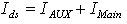 | (5) |
 | (6) |
 | (7) |
 | (8) |
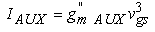
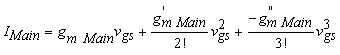
Where IAux is the current from the auxiliary transistor when biased below the threshold (cutoff) voltage. The transistors at the transconductance stage are in the saturation mode of operation with negative gm" while the transistors in the cutoff region have positive gm". As suggested by (8), the principle idea behind this technique is to add up the derivatives and to cancel the negative gm" of the transconductance transistors using auxiliary transistors biased below the conduction threshold. In fact, as shown in Figure 2, the auxiliary transistor is placed in parallel to the transconductance transistor to cancel gm" and improve linearity [13, 14]. | Figure 2. Auxiliary transistor and transconductance transistor in parallel combination [9-11] |
Depending on the technology used for this purpose, the width of the auxiliary transistor must be larger than that of the main transistor.The gm derivative and gm second derivative of improved common gate mixer in transconductance stage are shown in Figure 3. The gm second derivative of improved common gate mixer in transconductance stage and auxiliary transistors, also sum of them are shown in figure 4. 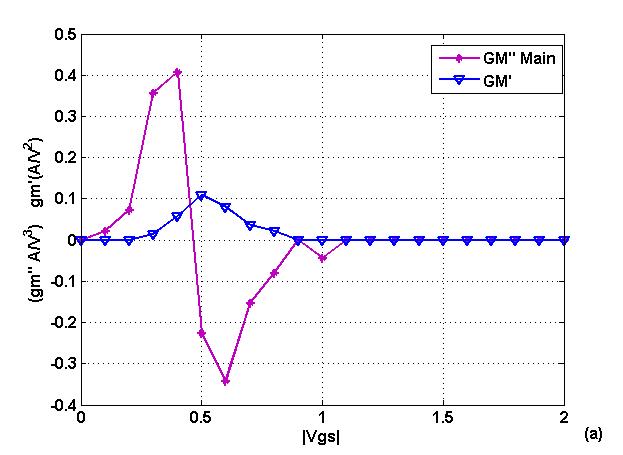 | Figure 3. gm' and gm" versus Vgs |
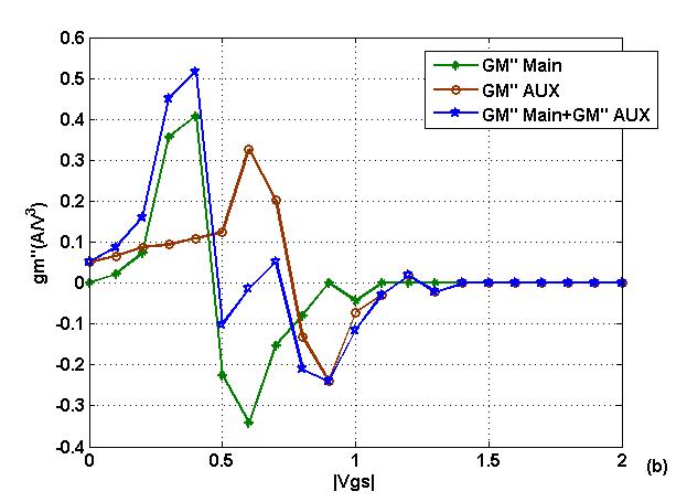 | Figure 4. Canceling gm" using MGTR |
This technique does not require additional power since the auxiliary transistor is operating in the cut-off mode. Several transistors may be used to improve linearity. However, studies have indicated that using more than two auxiliary transistors results in reduced gain and increased number of bias voltages for auxiliary transistor, which in turn add to complexity of the biasing circuit [9, 10]. In order to compensate for the capacitor resulting from the increased width of the transistors, an inductor must be added at the sources of the transistors to prevent gain drop and match impedances [6, 8]. Thus, in multiple gate arrangement, the negative peak value of gm" in the main transistor is cancelled by the positive value of gm" in the auxiliary transistor. Transfer characteristics may vary with changes in threshold voltage or gate bias.
4. Modified Common Gate Mixer
In the modified version of common gate Gilbert cell-based mixer, an inductor (LD) is added to compensate for the parasitic capacitance formed by M5, M6, M7, and M8. This inductor plays a significant role in enhancing linearity [13, 14]. MA1 and MA2 are auxiliary transistors which are parallel to the transconductance transistor and biased below the threshold level for conduction. When MA1 and MA2 are added to the circuit, the common gate mixer requires impedance matching and hence, the inductors LA1 and LA2 are used for this purpose. As seen in Figure 5, adding these three inductors and two transistors considerably improves linearity and enhances mixer performance without chaining transistor size and the bias voltage for the conventional common gate architecture. 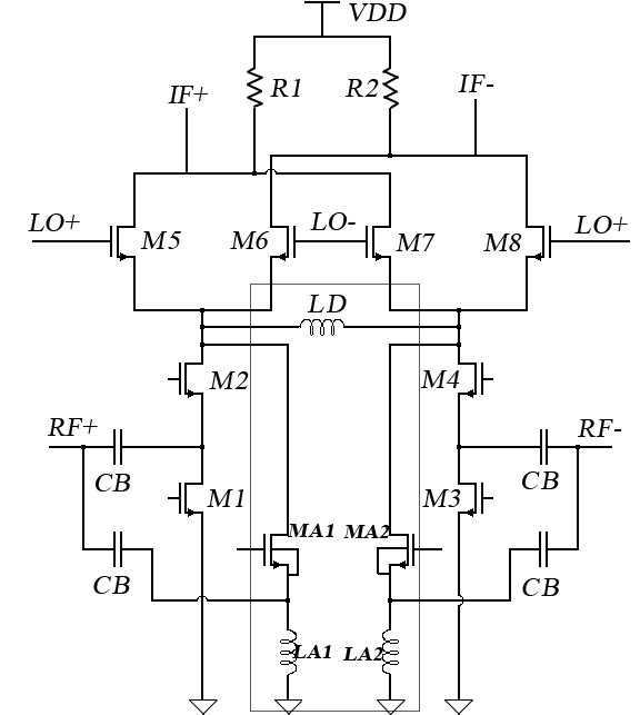 | Figure 5. Gilbert cell-based mixer, modified common gate architecture |
The inductor sizes are selected in such a way that makes it possible to implement the circuit on a completely integrated architecture. 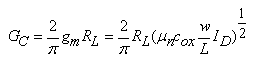 | (9) |
 | (10) |
 | (11) |
Equations (9), (10), and (11) show that at a constant current flowing through the load, an increase in Vgs (reduction in the size of input transistors) leads to larger IIP3 while reduction in gm results in smaller IIP3.
5. Simulation Results
Simulations were carried out in HSPICE RF using RF CMOS 0.18-µm technology. Figure 6 depicts return losses for a conventional common gate mixer. As mentioned earlier, inductors and capacitors are not used for impedance matching in conventional common gate structure. 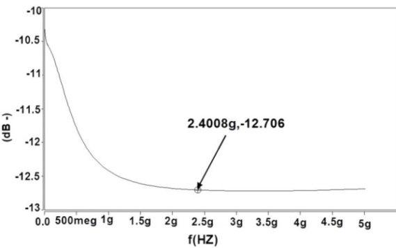 | Figure 6. Return loss (S11) for conventional common gate mixer |
Figure 7 illustrates return losses for modified common gate mixer. Figures 8 and 9 examine linearity in conventional and modified common gate mixers at 27 °C, respectively. 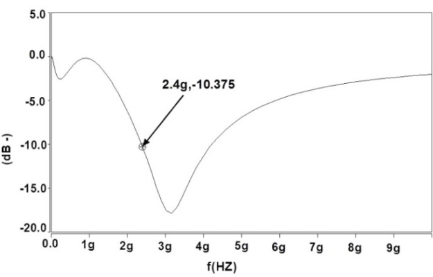 | Figure 7. Return loss (S11) for the modified common gate mixer |
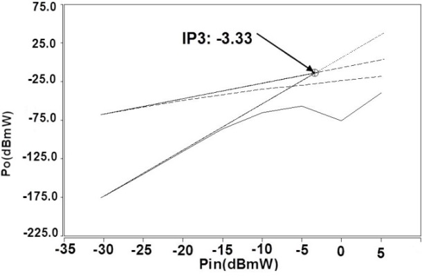 | Figure 8. IIP3 for conventional common gate mixer at 27 °C |
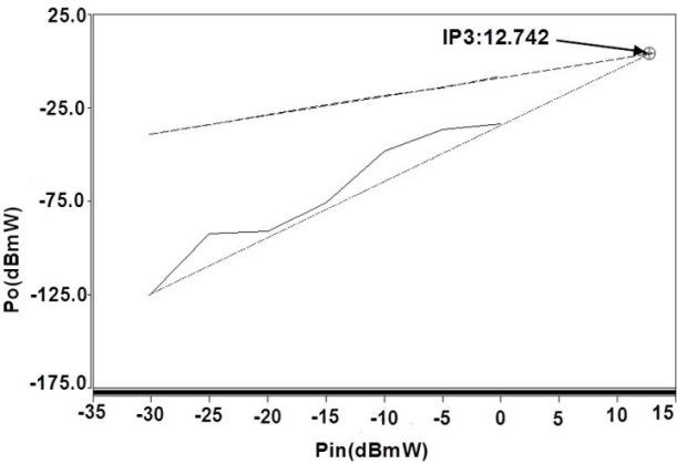 | Figure 9. IIP3 for the modified common gate mixer at 27 °C |
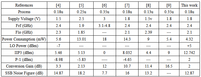
These results were obtained through harmonic balance analysis in a two-tone approach with the two main frequencies spaced at 10 MHz from each other. These findings indicate that linearity of the proposed common gate mixer is considerably higher compared to the conventional common gate mixers. Table 1 compares characteristics of the proposed mixer with other architectures while Tables 2 and 3 show variations in linearity of conventional and modified mixers against temperature. As seen in the tables, although linearity of the proposed mixer varies with temperature, it is still higher than linearity of conventional common gate mixers.Table 1. A comparison of characteristic features of the proposed mixer and other configurations
 |
| |
|
| Table 2. Variations in linearity of the conventional common gate mixer based on Gilbert cell versus temperature |
| | IIP3 (dBm) | Temperature (°C) | | -3.37 | 0 | | -3.33 | 27 | | -2.02 | 50 |
|
|
| Table 3. Variations in linearity of the modified common gate mixer based on Gilbert cell versus temperature |
| | IIP3 (dBm) | Temperature (°C) | | 5.009 | 0 | | 12.742 | 27 | | 9.899 | 50 |
|
|
6. Conclusions
Designing a highly-linear Gilbert cell mixer with minimum power consumption is not an easy task. One way to improve linearity of mixers is multiple gated transistors method which does not involve using complex circuitry while it acceptably improves linearity without increasing power consumption.Mixer linearity is improved 16 dBm by means of proposed method. The MGTR method is used in proposed mixer design. The proposed mixer linearity is improved without using any extra electrical power. The improved mixer linearity is made by means of three inductors and two auxiliary transistors without changing in transistor size of conventional common gate mixer.Disadvantages of MGTR include variation in linearity depending on implementation process, changes in temperature, and changes in bias voltage of the auxiliary circuit. Although these changes may be extensive, however, the improvements are still remarkable compared to the original architecture which does not employ auxiliary circuits. In addition, the capacitances resulting from this auxiliary circuit may reduce conversion gain.Linearization proposed method is well implemented on low-voltage, low-noise, power amplifiers and mixers because this method can be used to design integrated circuits in RF transceiver and front-end microwave.The proposed method needs shorter designing time than other modified method because transistor size doesn’t need to change.
ACKNOWLEDGMENTS
The authors wish to acknowledge Ali Yousefipour, Abdolamir Salempour, and Mahmoud Mokhtarband from MERAJ ICT Center for their valuable contributions that increased our interest in discussions on RF and microwave.
References
| [1] | B. Razavi, RF Micro Electronics, USA: Prentice Hall Inc., 1998. |
| [2] | Tanaka, S., Behbahani F., Abidi, A., 1997, A Linearization Technique For CMOS RF Power Amplifier, symposium on VLSI circuits digest of technical papers (IEEE), 93-94. |
| [3] | H. Darabi, A. Abidi, “Noise in RF-CMOS Mixers: A Simple Physical Model”, IEEE Journal of Solid-State Circuits, vol. 35, pp. 15-25, 2000. |
| [4] | Wei, H. CH., Weng, R. M., Hsiao, CH. L., Lin, K. Y., 2004, A 1.5V 2.4GHZ CMOS Mixer With High Linearity, The 2004 IEEE Asia-Pacific Conference on Circuits and Systems ( IEEE), Tainan, , 289-292. |
| [5] | V. Chandra, “A 2.5V High Linearity CMOS Mixer for 1.9GHZ Applications”, Carnegie Mellon University, 2003. |
| [6] | Douss, S., Touati, F., Loulou, M., 2007, A 3.1-4.8 GHZ CMOS Mixer Design Using Current Bleeding Technique for uwb MB-OFDM Receivers, The IEEE International Conference On Signal Processing and Communications (ICSPC 2007) (IEEE), Dubai, 89-92. |
| [7] | R. Heidari, S. Haddadian, H. Nabovati, “A Low Voltage High linearity CMOS Gilbert Cell Charge Injection Method”, World Academy of Science, Engineering and Technology, vol. 14, pp. 147-151, 2008. |
| [8] | S. K. Alam, J. Degroat, “A 2 GHZ Highly Linear Down Conversion Mixer in 0.18µ CMOS”, The Ohio State University, 2005. |
| [9] | T. Kim, B. Kim, K. Lee, “Highly linear Receiver front-end Adopting MOSFET Transconductance Linearization by Multiple Gated Transistors”, IEEE Journal of Solid-State Circuits, vol. 39, pp. 223-229, 2004. |
| [10] | B. Kim, J. KO, K. Lee, “A New Linearization Technique For MOSFET RF Amplifier Using Multiple Gated Transistor”, IEEE Microwave guided wavelet, vol. 10, pp. 371-373, 2000. |
| [11] | V. Aprin, L. E. Larson, “Modified Derivative Superposition Method for Linearizing FET-Low Noise Amplifiers”, IEEE Transactions on Microwave Theory and Techniques, vol. 53, pp. 571-581, 2005. |
| [12] | J. Yoon, H. Kim, CH. Park, J. Yang, H. Song, S. Lee, J. Yoon, H. Kim, C. Park, J. Yang, H. Song, S. Lee and B. Kim, “A New RF CMOS Gilbert Cell Mixer With Improved Noise Figure and Linearity”, IEEE Transactions on Microwave Theory and Techniques, vol. 56, pp. 626- 631, 2008. |
| [13] | Jin, L., Tang, Z., Min, H., 2007, A Low Noise High Linearity CMOS Up Conversion Mixer, The 7th International Conference ASIC (IEEE), china, 431-434. |
| [14] | M. Parvizi, A. Nabavi, “Low Power Highly Linear UWB CMOS Mixer with Simultaneous Second and Third-Order Distortion Cancellation”, Journal of Microelectronics, Elsevier, vol. 41, pp. 1-8, 2010. |
 Abstract
 Reference
 Full-Text PDF
 Full-text HTML