-
Paper Information
- Next Paper
- Paper Submission
-
Journal Information
- About This Journal
- Editorial Board
- Current Issue
- Archive
- Author Guidelines
- Contact Us
Electrical and Electronic Engineering
p-ISSN: 2162-9455 e-ISSN: 2162-8459
2013; 3(6): 167-172
doi:10.5923/j.eee.20130306.04
Design of Broadband Log Periodic Dipole Antenna Using Swarm Optimization
Umair Rafique1, M. Tausif A. Rana2
1Department of Electronic Engineering, Mohammad Ali Jinnah University, Islamabad, 44000, Pakistan
2Department of Electronic Engineering, Isra University, Islamabad, 44000, Pakistan
Correspondence to: Umair Rafique, Department of Electronic Engineering, Mohammad Ali Jinnah University, Islamabad, 44000, Pakistan.
| Email: |  |
Copyright © 2012 Scientific & Academic Publishing. All Rights Reserved.
This paper presents an optimized design for Log Periodic Dipole Array (LPDA) for WiMAX, GSM, DCS, Wi-Fi, 3G mobile communication and Bluetooth bands. First of all, the LPDA is designed by evaluating length, diameter and spacing between dipole elements. Then, the design is optimized by using evolutionary techniques called swam optimization and it is observed that the optimized design has smaller size and better gain than the conventional LPDA design. Thus, the optimization technique provides a cost effective solution with improved characteristics for LPDA.
Keywords: Log Periodic Dipole Array (LPDA), WiMAX, GSM, DCS, Wi-Fi, 3G Mobile Communication, Bluetooth, Swarm Optimization, Small Size
Cite this paper: Umair Rafique, M. Tausif A. Rana, Design of Broadband Log Periodic Dipole Antenna Using Swarm Optimization, Electrical and Electronic Engineering, Vol. 3 No. 6, 2013, pp. 167-172. doi: 10.5923/j.eee.20130306.04.
Article Outline
1. Introduction
- To accommodate large number of communication channels, a frequency independent antenna design is preferred. One of the powerful methods to address a requirement is designing of Log Periodic Dipole Array (LPDA). The initial work of LPDA with its mathematical description was carried out by Isbell and Carrel[1-2]. An LPDA is a wideband antenna whose characteristics are not affected by changing the spectrum of frequencies. Therefore, it is known as frequency independent antenna[3]. It consists of N number of dipole elements having unequal length, spacing and diameter. The main task in the designing of LPDA is the evaluation of current behaviour across the dipole elements[1]. The initial work to determine the current across dipole elements is carried out by King in 1957[4]. The design of an LPDA can be optimized by employing an optimization technique. There are numerous optimization techniques such as swarm optimization, genetic algorithm, artificial neural networks, etc. are frequently applied in electromagnetic related problems. Out of those techniques, swarm optimization and its different variants are considered powerful optimization tools which offer almost guaranteed convergence for complex problems[5-6]. PSO was successfully applied in various applications such as array design[7], device modelling[8], communications[9], etc.Previously, the design of an LPDA was presented with particle swarm optimization and genetic algorithm[10-11]. The purpose of the presented work was to increase the gain of an LPDA with the reduction in size. In this paper, the variant of swarm optimization which is Quantum Particle Swarm Optimization (QPSO) is used to optimize the physical variables of an LPDA for its potential applications in mobile communication. From the results, it is noted that the QPSO based design offers at least 12.69% improvement in gain and small size than the previously presented designs [10-11].
2. Swarm Optimization
- In swarm optimization, a particle tries to get a best position which is called its personal best pbest. There is also a best position with respect to the entire swarm called global best gbest. The number of parameters to be optimized for a given problem is a dimension of a swarm. A swarm is initialized with a random positions and velocities. To avoid explosion[12], sometimes, a search space is also define to ensure the confinement of particles within the defined space. For this purpose, one can define vmax by using following equation
 | (1) |
 | (2) |
 | (3) |
 | (4) |
 | (5) |
 | (6) |
 | (7) |
 | (8) |
 | (9) |
 | (10) |
3. LPDA Fundamental
- The successive dipole elements of an LPDA are connected alternatively with a balanced transmission line called feeder as shown in Figure 1. It is a self-complementary structure because of its periodicity[6]. The length of shortest and longest dipole element is determined by the upper and lower frequency. The ratio between length and diameter of two consecutive elements of an LPDA is given by[19]
 | (11) |
 | (12) |
 | (13) |
 | (14) |
 | (15) |
 | (16) |
 | (17) |
 | (18) |
 | (19) |
 | (20) |
 | (21) |
 | Figure 1. Design and geometry of Log-Periodic Dipole Array |
 | Figure 2. Radiation patterns of LPDA (a) E-plane and (b) H-plane |
4. Log Periodic Dipole Array Design
- Designing an LPDA for different wireless applications is a cumbersome process. The spectral band of interest in the proposed design is 400-2800 MHz. For the desired band, the conventional design parameters are listed in Table 1. The length, spacing and diameter of each dipole element are calculated by using Equations (11), (12) and (14). We choose 13 dipole elements for optimization and the initial/ conventional values of13diole elements are given in Table 2. After designing LPDA, we optimize it by using two optimization techniques which are PSO and QPSO. In order to optimize an LPDA, a fitness function is developed which based on the gain of an antenna and defined as
 | (22) |
 | (23) |
|
|
|
|
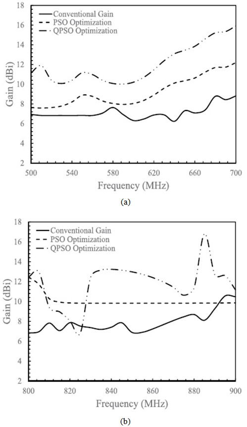
 | Figure 3. Conventional and optimized gain for (a) WiMAX and (b) GSM frequency bands |
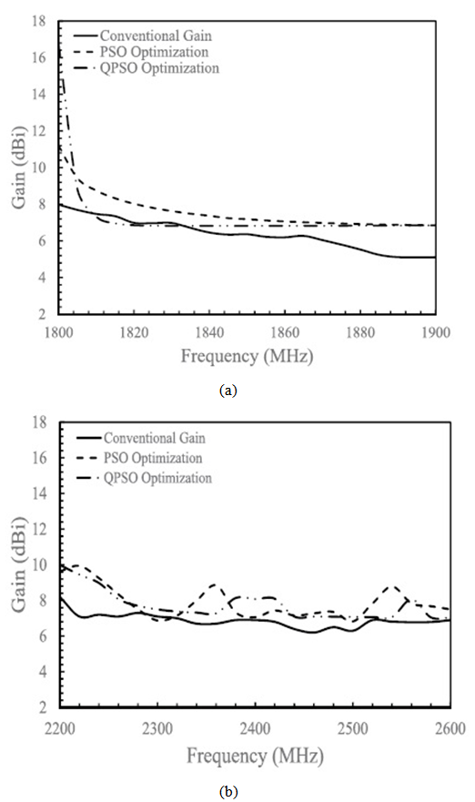
 | Figure 4. Conventional and optimized gain for (a) DCS and (b) Wi-Fi,, 3G mobile and Bluetooth frequency bands |
5. Conclusions
- A Log Periodic Dipole Antenna (LPDA) is designed by using conventional technique for microwave communication bands. The response as a gain is observed against the spectral band. After that the design is optimized by using stochastic techniques called PSO and QPSO. It is observed from the comparative optimized results that optimized design improved the gain for each frequency band compared to the conventional design. It is also noted that the optimized design is much smaller as compared to the conventional design.
ACKNOWLEDGEMENTS
- The authors are thankful to Dr. Muhammad Mansoor Ahmed, Executive Vice President of Mohammad Ali Jinnah University, Islamabad, Pakistan and Mr. Qamar-ud-Din Memon, Lecturer at NFC Institute of Engineering, Fertilizer and Research, Faisalabad, Pakistan, to giving us understanding about swarm optimization.
Nomenclature
- xi ith
 Particle positionvi ith
  Particle velocityxmax
  Maximum position xmin
  Minimum positionvmax
  Maximum velocityc1
  Cognitive componentc2
  Social componentϕ1, ϕ2
  Random numbersχ
  Random selected spacing factorω
  Inertia weightk
  Number of iterationsM
  Number of particles in swarmvpbest
  Personal best velocityvgbest
  Global best velocityj
  dimension of problemτ
  Scaling factorσ
  Spacing factorα
  Geometry of LPDAN
  Number of dipole elementsLn
  Length of nth dipole elementXn
  Distance from source to nth dipole elementhn
  Half-length of nth dipole elementDn
  Spacing between elementsdn
  Diameter of nth dipole elementIE
  Current across dipole elementsZE
  Impedance of dipole elementYF
  Admittance of feeder line
References
| [1] | Isbell, D., “Log periodic dipole arrays”, IRE Transactions on Antennas and Propagation, vol. 8, pp. 260-267, 1960. |
| [2] | Carrel, R., “The design of log-periodic dipole antennas”, IRE International Convention Record, vol. 9, pp. 61-75, 1961. |
| [3] | Rumsey, V. H., “Frequency independent antennas”, IRE International Convention Record, pp. 114-118, 1957. |
| [4] | King, H., “Mutual impedance of unequal length antennas in echelon”, IRE Transactions on Antennas and Propagation, vol. 5, pp. 303-313, 1957. |
| [5] | Eberhart, R. and Kennedy, J., “A new optimizer using particle swarm theory”, Proceedings of the 6th International Symposium on Microwave Machine and Human Science, pp. 39-43, 1995. |
| [6] | Pantoja, M. F., Bretones, A. R., Ruiz, F. G., Garcia, S. G. and Martin R. G., “Particle swarm optimization in antenna design optimization of log-periodic dipole arrays”, IEEE Antennas and Propagation Magazine, vol. 49, pp. 34-47, 2007. |
| [7] | N. Jin and Y.R.-Samii, “Particle swarm optimization for correlator antenna array designs in radio astronomy applications”, 2nd European Conference on Antennas and Propagation, pp. 1-4, 2007. |
| [8] | Sabat, L. S., Coelho, L. D. S. and Abraham, A., “MESFET DC model parameter extractions using quantum particle swarm optimization”, Microelectronics Reliability, vol. 49, pp. 660-666, 2009. |
| [9] | Z. Yangyang, I. J. Chunlin, Y. Ping, L. Manlin, W. Chaojin and W. Guangxing, “Particle swarm optimization for base station placement in mobile communication”, IEEE International conference on Networking, Sensing and Control, vol. 1, pp. 428-432, 2004. |
| [10] | M. A. Haq, M. T. Afzal, U. Rafique, Q.-ud. Din, M. A. Khan and M. M. Ahmed, “Log periodic dipole antenna design using particle swarm optimization”, International Journal of Electromagnetics and Applications, vol. 2, no. 4, pp. 65-68, 2012. |
| [11] | M. Touseef, Q. D. Memon, M. A. Haq, U. Rafique, M. A. Khan and M. M. Ahmed, “Genetic algorithm optimization of log-periodic dipole array”, International Journal of Electromagnetics and Applications, vol. 2, no. 6, pp. 169-173, 2012. |
| [12] | Clerc, M. and Kennedy, J., “The particle swarm explosion, stability and convergence in a multi-dimensional complex space”, IEEE Transactions on Evolutionary Computation, vol. 6, no. 1, pp. 58-73, 2002. |
| [13] | J. Kennedy, “The particle swarm: social adaptation of knowledge”, IEEE International Conference on Evolutionary Computation, pp. 303-308, 1997. |
| [14] | R. C. Eberhart and Y. Shi, “Comparing inertia weights and constriction factors in particle swarm optimizations”, Proceedings of the 2000 Congress on Evolutionary Computation, vol. 1, pp. 84-88, 2000. |
| [15] | Robinson, Y. and Samii, Y. R., “Particle swarm optimization in electromagnetics”, IEEE Transactions on Antennas and Propagation, vol. 52, pp. 397-407, 2004. |
| [16] | Lindsay, P. A., Quantum mechanics for electrical engineering, McGraw Hill, New York, 1967. |
| [17] | J. Sun, W. Xu, W. Fang and Z. Chai, “Quantum behaved particle swarm optimization with binary encoding”, 8th International Conference on Adaptive and Natural Computing Algorithms, pp. 376-385, 2007. |
| [18] | F. S. Levin, An Introduction to Quantum Theory, Cambridge University Press, New York, 2002. |
| [19] | C. A. Balanis, Antenna Theory and Design, 3rd Edition. |
| [20] | Bantin, C. and Balmain, K., “Study of compressed log-periodic dipole antennas”, IEEE Transactions on Antennas and Propagation, vol. 18, no. 2, pp. 195-203, 1970. |
| [21] | R. F. Harrington, Field Computation by Moment Methods, Robert E. Krieger Publishing Company,1985. |
 Abstract
 Reference
 Full-Text PDF
 Full-text HTML