Electrical and Electronic Engineering

p-ISSN: 2162-9455    e-ISSN: 2162-8459

2013;  3(4): 118-121

doi:10.5923/j.eee.20130304.03

Rectangular Planar Antenna Using U-Slot for Bandwidth Improvement

R. Dakir1, J. Zbitou2, A. Mouhsen1, A. Tribak3, Angel Mediavilla Sanchez4, M. Latrach5

1Laboratoire MMII Faculté des Sciences et Techniques, Settat, Morocco

2Laboratoire LITEN, FST de Settat, Morocco

3Institut national des postes et télécommunications, Rabat, Morocco

4Laboratoire DICOM, Santander, Spain

5RF & Hyper group, ESEO, Angers, France

Correspondence to: J. Zbitou, Laboratoire LITEN, FST de Settat, Morocco.

Email:

Copyright © 2012 Scientific & Academic Publishing. All Rights Reserved.

Abstract

This paper presents the design and the achievement of a coplanar compact broadband microstrip antenna. The proposed antenna has a wide matching input impedance with a return loss less than -10dB. This antenna is developed to widen the narrow bandwidth of a microstrip rectangular patch. The antenna structure is designed, optimized and miniaturized by using Momentum software integrated into ADS ”Advanced Design System” and compared with CST Microwave Studio. The final broadband antenna is achieved by using FR4 substrate.

Keywords: Microstrip Antennas (MSA), Wide Band Antennas, Bandwidth Improvement, Narrow Bandwidth

Cite this paper: R. Dakir, J. Zbitou, A. Mouhsen, A. Tribak, Angel Mediavilla Sanchez, M. Latrach, Rectangular Planar Antenna Using U-Slot for Bandwidth Improvement, Electrical and Electronic Engineering, Vol. 3 No. 4, 2013, pp. 118-121. doi: 10.5923/j.eee.20130304.03.

1. Introduction

Nowadays, with the rapid development of the modern wireless communications technologies (WIMAX: Worldwide Interoperability for Microwave Access, RFID: radio frequency identification, WIFI: Wireless Fidelity), there has been an increasing demand for the development of the broadband antennas. Therefore, the needs of broadband antennas have pushed research efforts to improve and miniaturize the narrow bandwidth antennas. Microstrip antennas are popular for their attractive futures such as low profile, low height, low cost, easy fabrication. On the contrary, the major disadvantage of these types of antennas is the lower and narrow bandwidth[1-5].
Combination of the coplanar waveguide feed, antenna geometry, and a variety of slot shapes is a solution to improve and enlarge the antenna operating bandwidth[6-8].
Many configurations have been studied such as Coplanar Waveguide (CPW) feed slot antenna[9-12], in which bandwidth enhancement techniques for microstrip antennas were extensively investigated[13-21]. In this paper, a new low cost broadband coplanar antenna is designed and achieved by using slot techniques. Due to the nature of the feed line that is CPW one, the achieved antenna is suitable for integration with passive and active components.

2. The Conception of Broadband Microstrip Antenna

2.1. Design Procedures

Firstly, the aim of this study is to improve the bandwidth of the rectangular patch antenna presented in figure.1. Secondly, the final antenna structure should be compact and easy to be integrated with microstrip circuits’ components. To start the design, series of optimizations is conducted by using electromagnetic simulations.
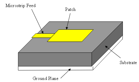
Figure 1. Microstrip rectangular patch antenna
The antenna structure designed is based on a CPW feed line, with the use of slot techniques to widen the narrow bandwidth, taken into consideration the gain and directivity.
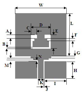
The geometry of the proposed antenna is shown in Figure2. It is simulated by using FR4 epoxy substrate with relative permittivity εr=4.3, thickness of h=1.6 mm, and total area of 40x49 mm2. The microstrip antenna is excited by a Coplanar Waveguide with 50Ω characteristic impedance. The dimensions of the antenna are optimized and miniaturized by using ADS” Advanced Design System”. After many optimizations, the dimensions of the final structure are shown in Table 1.
Figure 2. The Geometry of the proposed antenna
Table 1. Antenna dimensions in (mm)
ParameterValue
A2.5
B1
C3.5
D11.5
E9.5
F2
G1
H12.5
I12.9
J0.5
K3.2
M0.5
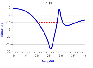
As shown in figure.3, the antenna validated into simulation has a bandwidth from 2 GHz to 2.7 GHz.
Figure 3. The return loss versus frequency in GHz
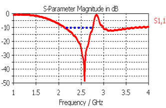
Before achieving the antenna, a second study is conducted by using CST” Microwave Studio”, that is a 3D electromagnetic simulator. After the simulation, the following result is obtained:
Figure 4. Return Loss versus frequency on CST
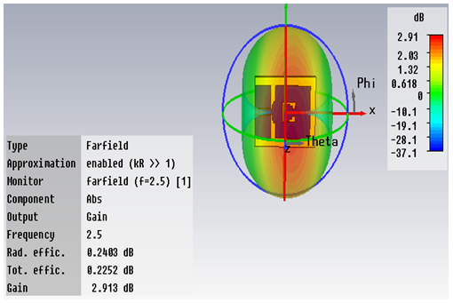
For radiation pattern, figure.5 presents the 3D antenna radiation for 2.5 GHz.
Figure 5. The 3D radiation pattern of the antenna optimized

2.2. Achievement & Measurement

After the comparison of simulation results on ADS and CST, the antenna structure is achieved by using LPKF machine as shown in figure.6.
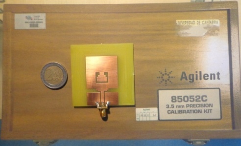
Figure 6. The achieved broadband antenna
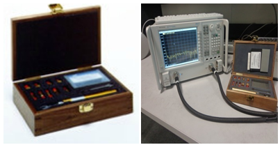
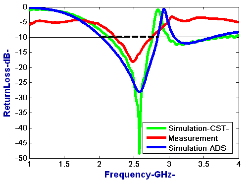
The measurement is performed with a Vector Network Analyzer (VNA) from Rohde & Schwarz R&S@ZVB20. The kit of calibration used is 3.5 mm composed from Open, Short and Load components; losses in the different transitions are taken into account. Measured input impedance bandwidth (return loss less than -10 dB) is 500 MHz (2.2-2.7 GHz).
Figure 7. Calibration Kit 3.5 mm
After the calibration, the return loss for the achieved antenna as shown in the following figure is tested. In the same time, both the simulations on ADS and CST with measurement results are compared.
Figure 8. Comparison of the simulated and measured return loss versus frequency
It is clearly observed that the simulation results on ADS are the closest to the measured results. This allows the validation of the broadband antenna structure from 2.2 GHz to 2.7GHz, with a band of 500 MHz, compared to that of a classical microstrip rectangular patch antenna.
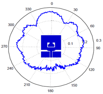
For the measured radiation pattern in Anechoic chamber at 2.5 GHz, it’s presented in figure 9.
Figure 9. Radiation pattern @ 2.5 GHz

3. Conclusions

In this study, we have performed the conception and the achievement of a new low cost rectangular planar antenna by using slot technique for bandwidth improvement. After many optimizations of the antenna structure, we have validated the antenna structure with a bandwidth of 500MHz. This achieved antenna is feed with CPW line which is easy to integrate it with passive and active printed circuits broad components.

ACKNOWLEDGMENTS

We fully thank Mr. Angel Mediavilla Sanchez Director of DICOM Laboratory in Santander in Spain and Mr. Mohamed Latrach Professor in ESEO France, for allowing us to use and perform simulations by using softwares and measurement on the VNA, LPKF machine and Anechoic chamber.

References

[1]  J. Jia-Yi Sze, Chung-I. G. Hsu, Zhi-Wei Chen, andChi-Chaan Chang ,”Broadband CPW-Fed Circularly Polarized Square Slot Antenna With Lightening-Shaped Feedline and Inverted-LGrounded Strips”, vol. 58 , no.3, March,2010.
[2]  C. A. Balanis, John Wiley & Sons “Antenna theory: analysis and design”, Publication, 2005.
[3]  RongLin Li,Bo Pan, Joy Laskar, and Manos M. Tentzeris “A Novel Low-Profile Broadband Dual-Frequency Planar Antenna for Wireless Handsets”,vol. 56, no. 4, April, 2008.
[4]  M. Khalily, M. Kamal, A. Rahim, A. Khalajmehrabadi ,M. R. Kamarudin “A Compact Circularly Polarized and Wideband Rectangular Dielectric Resonator Antenna”, Seremban, Malaysia, IEEE International RF and Microwave Conference (RFM 2011).
[5]  L.Guo, S. Wang, X. Chen and C.G.Parini, ‘’Study of a compact antenna for UWB applications’’, IET Electronic Letters, pp. 115-116, vol. 46, no. 2, January 21st, 2010.
[6]  G. DeJean, R. L. Li, J. Laskar, and M. M. Tentzeris “Circularly Polarized Loop Antennas with a Parasitic Element for Bandwidth Enhancement”, pp. 401 - 404 vol, 1B, 2005.
[7]  R. L. Li, V. Fusco, and H. Nakano, "Circularly polarized open-loop antenna," IEEE Trans. Antennas Propagation,vol. 51, no. 9, pp. 2475-2477, Sept. 2003.
[8]  M. Sumi, K. Hirasawa, and S. Shi, "Two rectangular loops fed in series for broadband circular polarization and impedance matching", IEEE Trans. Antennas Propagation , vol. 52, no. 2, pp. 551-554, Feb. 2004.
[9]  X. Zhou, X. Quan, and RongLin Li “A Dual-Broadband MIMO Antenna System for GSM/UMTS/LTE and WLAN Handsets, Annas and Wireless Propagation Letters, IEEE, vol. 11,2012.
[10]  Amit A. Deshmukh and K. P. Ray Broadband Proximity-Fed Modified Rectangular Microstrip Antennas IEEE Antennas and Propagation Magazine, vol. 53, no. 5, October, 2011.
[11]  R. Chair, K . F . Lee, C. L. Mak, K. M. Luk and A. A. Kishk, "Miniature Wideband Half U-Slot And Half E Patch Antennas," IEEE Transactions on Antennas and Propagation, pp. 2645-2652, August, 2005.
[12]  Amit A. Deshmukh and G. Kumar, "Compact Broadband E-Shaped Microstrip Antennas", Electronics Letters, 41, 1 8,, pp. 989-990, 2005.
[13]  K. P. Ray, V. Sevani and Amit A. Deshmukh, "Compact Gap-Coupled Microstrip Antennas for Broadband and Dual Frequency Operations," International Journal of Microwave and Optical Technology, 2, 2, pp. 1 93-202, July,2007.
[14]  Amit A. Deshmukh and K. P. Ray, “Broadband Reactively coupled E-shaped Microstrip Antennas”, Proceedings of NCC, IIT Madras, India, Jan. 29 – 31,2010.
[15]  M. Palandoken, A. Grede, and H. Henke “Broadband Microstrip Antenna With Left-Handed Metamaterials”, pp. 331 - 338 VOL. 57, NO. 2, February, 2009.
[16]  W. Q. Cao, B.N. Zhang, A. J. Liu, T. B. Yu, D.S. Guo, and Y. Wei,”Gain Enhancement for Broadband Periodic Endfire Antenna by Using Split-ring Resonator Structures,” IEEE Trans. Antennas Propag.,vol. 60,no 7, pp. 3513-3516, 2012.
[17]  M. D. Sharma, A. Katariya, A. K. Pandit, “Design and Simulation of Broad Band Aperture Coupled Microstrip Antenna”, pp. 62-65, 2012.
[18]  K. M. Luk, C L. Mak, R Chair, H Wong, and K F. Lee. “Microstrip antennas broadband”, Encyclopedia of RF and Microwave Engineering. New York, 2005.
[19]  A Khidre, K. F. Lee, F. Yang, and A. Eisherbeni “Wideband Circularly Polarized E-Shaped Patch Antenna for Wireless Applications” IEEE Antennas and Propagation Magazine, Vol. 52, No.5, October 2010.
[20]  L.Guo, S. Wang, X. Chen and C.G.Parini, "Study of a compact antenna for UWB applications", IET Electronic Letters, pp. 115-116,vol. 46, no. 2, January 21st, 2010.
[21]  Athar Shahzad Fazal, Shabana Hafeez, Mushtaq Ahmed, K.S.Alimgeer, Y.wani, “Analysis of Coupled Microstrip Lines with DGS UWB Printed Filter” International Journal of Technology and Research, Vol.1 no.1 pp. 21-24, 2013.