-
Paper Information
- Previous Paper
- Paper Submission
-
Journal Information
- About This Journal
- Editorial Board
- Current Issue
- Archive
- Author Guidelines
- Contact Us
Electrical and Electronic Engineering
p-ISSN: 2162-9455 e-ISSN: 2162-8459
2013; 3(2): 72-76
doi:10.5923/j.eee.20130302.05
Electric Charging/Discharging Characteristics of Capacitor, Using De-alloyed Si-20Al Alloy Ribbons
 Abstract
 Reference
 Full-Text PDF
 Full-text HTML
1Research Institute for Electromagnetic Materials, Sendai, 982-0807, Japan
2Fracture & Reliability Research Institute, Tohoku University, Sendai, 980-8579, Japan
Correspondence to: M. Fukuhara, Research Institute for Electromagnetic Materials, Sendai, 982-0807, Japan.
| Email: |  |
Copyright © 2012 Scientific & Academic Publishing. All Rights Reserved.
Temperature and voltage dependencies of capacitance of de-alloyed Si-20 at%. Al alloy ribbons were measured as a function of frequency between 1m Hz and 100 kHz, using exponential transient analysis for electric charging/discharging. In sharp contrast to conventional electric double layer capacitor (EDLC), the capacitance of the specimen obtained by prompt (below 0.1 s) charging/discharging has not substantially changed in temperature region from 193 to 423 K and voltage variation from 10 to 150 V, showing direct electric storage without solvents. The capacitance charging/discharging efficiency ratios is almost the same as 97 % in temperature region from 193 to 423 K and voltage variation from 10 from 150 V. Thus the de-alloyed alloy can be regarded as a “dry” capacitance cell composed of distributed constant equivalent circuits.
Keywords: De-Alloyed Si-Al, Electric Charging/Discharging, Temperature Dependence, Voltage Dependence, Electric-Distributed Constant Capacitor
Cite this paper: M. Fukuhara, Electric Charging/Discharging Characteristics of Capacitor, Using De-alloyed Si-20Al Alloy Ribbons, Electrical and Electronic Engineering, Vol. 3 No. 2, 2013, pp. 72-76. doi: 10.5923/j.eee.20130302.05.
Article Outline
1. Introduction
- Electric storage is one of the topics currently attracting a great deal of interest in the field of energy source technology[1-6]. It can be accomplished by electrochemical devices and physical media. Much attention has been devoted to electrochemical energy storage for future electronic devices and electric power application, and storage of renewable energy for the power grid[7, 8].Recently, we have found a (Ni0.36Nb0.24Zr0.40)90H10 glassy alloy, showing Coulomb dot oscillation at room temperature[9] and a semi-true circular Nyquist diagram with total capacitance of 17.8 µF[10], derived from a large number of 0.23-nm-capacitors with femtofarad capacitance among its distorted icosahedral Zr5Ni5Nb3 clusters (dots of ca. 0.55 nm in size[11, 12]). However, it was difficult for the (Ni0.36Nb0.24Zr0.40)90H10 glassy alloy to discharge promptly discharging, because of a polarized glutinous liquid that is absorbed between pairs of metallic clusters[13].In previous paper[14], with a view to promoting the prompt discharging, we have reported that de-alloyed crystalline Si1–xAlx (x = 0.2, 0.3, and 0.4) alloy ribbons with resistivities of 1–1000 Ωcm showed charging/discharging properties of 105 µF (0.55 F/cm3) during prompt period of 0.1 s at 1 mHz near dc current. Si grains were surrounded by many nanometer-sized canyons which are leached out by HCl acid treatment. It was considered that electric charge is stored into large numbers of canyons. From the observed electrode distance dependence on capacitance and nonlinear electronic transport behavior, we deduced that the alloy consisted of an electric distributed constant equivalent circuit (series with 1.7 % parallel), analogous to conventional electric double layer capacitors (EDLC)[15, 16]. Since the I-V characteristics showed Schottky junction[17], we found that the Si skeleton and Al backbone are to an electron what active carbon is to the electrolyte solution in EDLC.In this study, we report temperature and voltage dependences of charging/discharging characteristics for the de-alloyed Si-20 at.% Al alloy ribbons with electric resistivity of 3 kΩcm. Si with forbidden band of 1.1 eV at room temperature is not dielectrics, which is characterized by forbidden band over about 2.5 eV, but semiconductor. Storage of electric charge in metals and alloys has to been overlooked in the literature, as far as we know. If we can store electricity in ac current, we can propose disuse of power transmission lines.
2. Experimental
- The rotating wheel method under an argon atmosphere was used for preparing Si-20at%.Al alloy ribbons of 1 mm width and a thickness of about 50 µm. using rotating speed of 31.4 m/s. De-alloying of the samples was carried out for 259.2 ks in 1N HCl solution at room temperature. The details of the procedure have been described in previous paper[12].Capacitances were calculated as a function of frequency between 1m Hz and 100 kHz from electric charge/discharge pulse curves of 10-150 V applied at 25 ns~0.1 s intervals, using a mixed-signal oscilloscope (MSO 5104, Tektronix) and 30 MHz multifunction generator (WF1973, NF Co.) on the basis of a simple exponential transient analysis. The schematic diagram for measurement of ribbon specimen is shown in Fig. 1 a. The distance between the two electrodes was 2 mm. Two gold wires each having a diameter of 100 µm were soldered to the alloy ribbon. We used an isothermal furnace in the temperature region from 193 to 423 K in air at ambient pressure. The charging/discharging efficient ratio was calculated from integration of transient curves for charging/discharging.
3. Results and Discussion
3.1. Temperature and Voltage Dependent Capacitance
- Since the de-alloyed Si-20 at.% Al is composed of distributed constant equivalent circuits of series C with 1.7 %parallel C[14], we cannot use the LCR meter which are measured on the basis of the parallel or series We measured the voltage transient phenomena as a function of time for charging and discharging in input and output circuits. The representative results for 1 mHz at 100V are presented at Figs. 1(b) and (c). Transient analysis of Figs. 1(b) and (c) gave capacitance values of 92.0 and 93.5 μF for charging and discharging, respectively. Since both values are almost the same, the capacitance value for discharging hereafter serves conveniently as capacitance one.
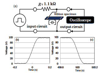 | Figure 1. A sample line graph using colors which contrast well both on screen and on a black-and-white hard copy |
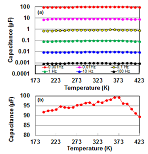 | Figure 2. (a) The temperature dependence of capacitance at 0.001, 0.01, 0.1, 1, 10, and 100 Hz in the temperature region from 193 to 423 K; (b) the temperature dependence of capacitance at 1 mHz in the temperature region from 193 to 423 K |
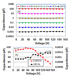 | Figure 3. (a) The voltage dependence of capacitance at 0.001, 0.01, 0.1, 1, 10, and 100 Hz in the voltage region from 10 to 150 V; (b) the temperature dependence of capacitance at 1 mHz in the temperature region from 10 to 150 V |
3.2. Frequency Dependent Capacitance
- Capacitances as a function of frequency for temperature and voltage are presented logarithmically in Fig. 4(a) and (b), respectively. Temperature dependent capacitances decreased parabolic from around 0.1 mF (0.54 F/cm3) to around 50 pF (0.3 µF/cm3) with increasing frequency and saturated in frequency region over 10 kHz. Here it should be noted that charging/discharging of electrochemical cells occurs at lower frequency regions on the whole interfaces in pores of electrodes, but does not occur at higher frequency ones in interior parts of pores[19]. Hence, by analogy we infer that that the de-alloyed Si-Al alloy, which shows large frequency dependence on capacitance independent of temperature, is an assembly of canyons with the deepest recess.
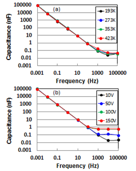 | Figure 4. Frequency dependence of capacitance for temperature at 193, 273, 353, and 423 K (a), and voltage at 10, 50, 100, and 150 V (b) |
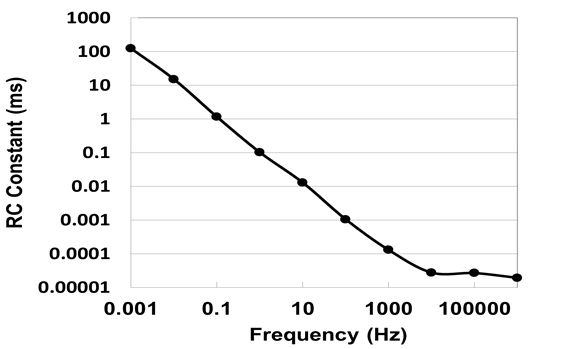 | Figure 5. Frequency dependence of RC constant in input voltage of 10 V at room temperature |
3.3. Temperature and Voltage Dependencies on Charging/Discharging Efficiency Ratio
- Lastly, we analyze temperature and voltage dependencies on charging/discharging efficiency ratio. These results are shown at Fig. 6(a) and (b), respectively. Both efficiencies are almost the same as 97.0 % in temperature region from 193 to 423 K and voltage variation from 10 to 150 V. This means an inevitable leaking of 3 % for electric charge independent of temperature and voltage. Although the value is in quit agreement with that[16] of EDLC at room temperature, the EDCC of interest shows superior performance in electrically storing at high temperatures and voltages, where EDLC cannot be used.
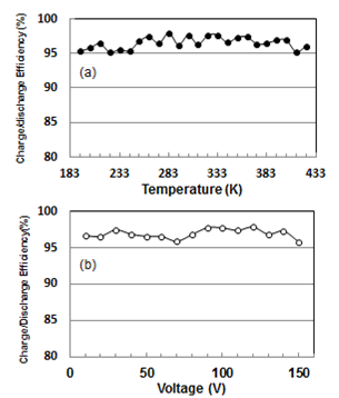 | Figure 6. Temperature (a) and voltage (b) dependencies on charg ing/discharging efficiency ratios at 1 mHz |
4. Conclusions
- Capacitance of de-alloyed crystalline Si-20 at.% Al alloy ribbon was investigated as functions of temperature and voltage in comparison with EDLC. The temperature dependent capacitances of the specimen decreased parabolic from around 100 µF (0.54 F/cm3) to around 50 pF (0.3 µF/cm3) with increasing frequency up to 10 kHz, before becoming saturated in the frequency region over 10 kHz. This indicates distinct ac current momentary (below 0.1 s) charging/discharging, showing electron storage in Si-based solid cell without solvents. The de-alloyed Si-Al alloy is completely different from the conventional “wet” cells such as EDLC and secondary cells which are controlled by diffusivity of ions. Therefore we can regard it as “dry” EDCC. The temperature and voltage dependent capacitances showed relatively small loss (3 %) in wide temperature between 193 and 423 K, and voltage region between 10 and 150 V. Thus the EDCC shows superior performance in electrically storing at high temperatures and voltages, where EDLC cannot be used.
ACKNOWLEDGEMENTS
- The author would like to thank Mr. T. Takahashi for the preparation of alloy ribbons. This work was supported by a Grant-in-Aid for Science Research in a Priority Area, ‘Advanced Low Carbon Technology Research and Development Program’, from the Japan Science and Technology, Japan.