Ana Vučković1, Slavoljub Aleksić1, Saša Ilić1, Alexander Tatarenko2, Roman Petrov2, Mirza Bichurin2
1Faculty of Electronic Engineering of Niš, University of Nis, Niš, 18000, Serbia
2Institute of Electronic and Information Systems, Novgorod State University, Veliky Novgorod, 173003, Russia
Correspondence to: Roman Petrov, Institute of Electronic and Information Systems, Novgorod State University, Veliky Novgorod, 173003, Russia.
| Email: |  |
Copyright © 2012 Scientific & Academic Publishing. All Rights Reserved.
Abstract
The paper presents calculation of the force between two ring permanent magnets whose magnetization is axial. Such configuration corresponds to a passive magnetic bearing. Magnets are made of the same material and magnetized uniformly along their axes of symmetry, with the same intensity and same direction. The simple and fast analytical approach is used for this calculation based on magnetization charges and discretization technique. The results for interaction magnetic force obtained using proposed approach are compared with finite element method using FEMM 4.2 software. The proposed algorithm can be used for calculation of microwave devices based on magnetoelectric materials with the use of permanent magnets.
Keywords:
Permanent Magnet, Interaction Magnetic Force, Magnetization Charges, Discretization Technique, Finite Element Method (FEM)
Cite this paper: Ana Vučković, Slavoljub Aleksić, Saša Ilić, Alexander Tatarenko, Roman Petrov, Mirza Bichurin, Attraction Magnetic Force Calculation of Axial Passive Magnetic Bearing, Electrical and Electronic Engineering, Vol. 3 No. 2, 2013, pp. 43-48. doi: 10.5923/j.eee.20130302.03.
1. Introduction
Permanent magnets are used nowadays in many applications, and the general need for dimensioning and optimizing leads to the development of calculation methods. Permanent magnets are commonly used in many electrical devices and their own quality depends on the magnet material, magnetization and dimensions. Most engineering applications need several ring permanent magnets and the determination of the magnetic force between them is thus required. Magnetic bearings are contactless suspension devices with various rotating and translational applications[1]. Depending on the ring permanent magnet magnetization direction, the devices work as axial or radial bearings and thus control the position along an axis or the centering of an axis. There are numerous techniques for analyzing permanent magnet devices and different approaches for determining interaction forces between them[2-5]. The authors generally use the Ampere's current model[2,3] or the Columbian approach[4].
2. Theoretical Background
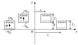
Axial passive magnetic bearing[6] that is considered in the paper is presented in the Figure 1. Since the boundary condition for fictitious surface magnetization charges density has to be satisfied for both magnets,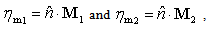 | (1) |
it is obvious that fictitious surface magnetization charges exist only on the bottom and the top bases of each permanent magnet, because volume magnetization charges for uniform magnetization do not exist.  is the unit vector normal to surface.
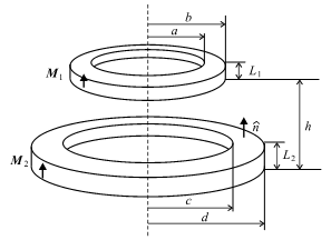 | Figure 1. Axial passive magnetic bearing |
The simplest procedure for interaction magnetic force determination is to discretize each base of both permanent magnets into system of circular loops[7]. The interaction force between two magnetized circular loops will be calculated first. That will be performed by calculating the magnetic field and magnetic flux density generated by the arbitrary magnetized circular loop of the upper magnet first and then the force that acts on the arbitrary loop of the lower magnet (Figure 2). Using results for interaction magnetic force between two circular loops, magnetic force of the axial magnetic bearing can be obtained by summing the contribution of both magnet bases of lower and upper permanent magnets by using uniform discretization technique.The goal of this approach is to determine the interaction magnetic force between two circular loops uniformly loaded with magnetization charges  and
and  . Dimensions and positions of the loops are presented in the Figure 2. For determining the interaction force between two circular loops, magnetic scalar potential, magnetic field and magnetic flux density generated by the upper loop will be calculated. Elementary magnetic scalar potential generated by the elementary point magnetization charge,
  , is
, is | (2) |
 | Figure 2. Axial Two circular loops |
Since  , elementary magnetic scalar potential has the following form
  | (3) |
and the resulting magnetic scalar potential generated by the upper circular loop at an arbitrary point P(r,θ,z) is | , (4) |
Considering the existing symmetry, in θ = 0 plane, magnetic scalar potential has the following form | (5) |
Substituting θ′ = π − 2α in Eq. (5), magnetic scalar potential is obtained as: | . (6) |
After some simple operations the magnetic scalar potential can be given in the form: | (7) |
where  , is complete elliptic integral of the first kind with modulus
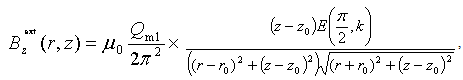
  .External magnetic field (magnetic field generated by the upper loop) at an arbitrary point can be determined as
 | (8) |
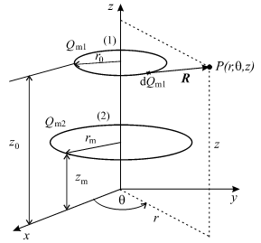
External magnetic flux density is  | (9) |
 | (10) |
with components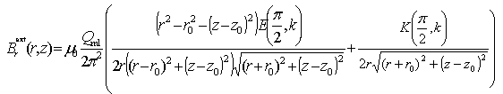 | (11) |
 | (12) |
where  , is complete elliptic integral of the second kind with modulus
 .The interaction magnetic force on elementary magnetization charge of lower circular loop
 | (13) |
Finally, interaction magnetic force components can be expressed as: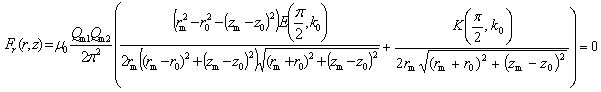 | (14) |
 | (15) |
 | Figure 3. Discretizing model |
with elliptic integrals modulus The axial component of the force (15) presents interaction force between two magnetized circular loops. The simplest procedure for attraction magnetic force determination is to discretize each bases of permanent magnets into system of circular loops, where N1 is the number of discretized segments of each bases of upper permanent magnet and N2 is the number of discretized segments of each bases of lower permanent magnet.By taking into account the ring geometry of permanent magnets (Figure 3), the radius of each discretized segment of both bases of upper magnet is
 | (16) |
and magnetization loop charges of upper permanent magnet bases are | (17) |
For lower magnet bases the radius of each discretized segments is  | (18) |
Magnetization loop charges of lower permanent magnet bases are 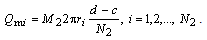 | (19) |
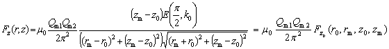
Using results for interaction magnetic force between two circular loops, Eqs. (15), the attraction magnetic force between two ring permanent magnets can be obtained. It can be achieved by summing the contribution of both magnet bases of lower and upper permanent magnets by using uniform discretization technique,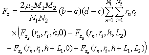 | (20) |
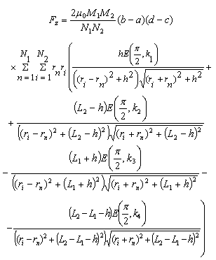 | (21) |
where 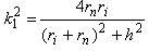 ,
,  ,
,  ,
, .
.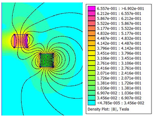 | Figure 4. Distribution of magnetic flux density for magnetic bearing (FEMM 4.2 software) |
3. Numerical Results
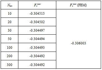
Presumption is that both ring permanent magnets are made of the same material and magnetized uniformly along their axis of symmetry in the same direction, M1 = M2 = M. Distribution of magnetic flux density obtained using FEMM 4.2 software[8] is presented in the Figure 4. The values of the geometrical parameters used in the numerical computation are: a/L2=1, b/L2=2, c/L2=3, d/L2=4, L1/L2=1, h/L2=1.5, L2=1mm and M=900 kA/m.Convergence of the normalized attraction force, 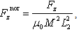 obtained using presented approach is given in Table 1 for magnetic bearing dimensions: a/L2=1, b/L2=2, c/L2=3, d/L2=4, L1/L2=1, h/L2=1.5.In order to save the calculation time, the number of segments is limited on Ntot = N1 + N2 = 200 because it is not necessary to take a greater number of segments to obtain a desired accuracy.
Table 1. Convergence of attraction magnetic force versus number of segments
 |
| |
|
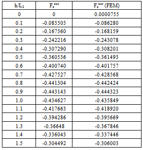
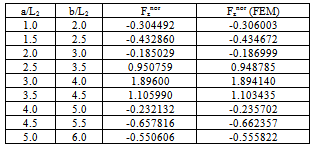
Compared results for normalized attraction magnetic force of two identical ring permanent magnets, obtained using presented analytical approach and finite element method (FEM) versus h/L2, for parameters: a/L2=1, b/L2=2, c/L2=3, d/L2=4 and L1/L2=1 are given in the Table 2. Comparative results for normalized interaction magnetic force of axial passive magnetic bearing versus ratios a/L2 and b/L2, obtained using presented approach and finite element method (FEM), for parameters: c/L2=3, d/L2=4, L1/L2=1 and h/L2=1.5 are shown in the Table 3. Table 2. Compared results for attraction magnetic force versus h/L2
 |
| |
|
Table 3. Compared results for interaction magnetic force versus a/L2 and b/L2
 |
| |
|
4. Microwave Devices Based on Magnetoelectric Materials with the Use of Permanent Magnets
Magnetoelectric (ME) composites that simultaneously exhibit ferroelectricity and ferromagnetism have been of recent research interest due to their potential for applications in multifunctional devices[9].A main feature of ME devices consists in the application of special permanent magnets[10]. For example, a design of ME microwave phase shifter using the permanent magnets to create of the bias magnetic field is shown in Figure 5. 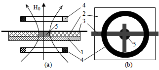 | Figure 5. Cross-section (a) and top view (b) ME microwave phase shifter. 1 - basis, 2 - substrate, 3 - microstrip line with a circuit-resonator, 4 - passive magnetic bearings, 5 - ME element |
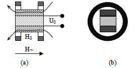 | Figure 6. ME sensor of alternating electromagnetic field, longitudinal section (a), lateral view (b) |
The ME phase shifter uses the inverse ME effect and operates as follows. Microwave energy passes through the microstrip line with a circuit-resonator. ME element is placed in the center of the substrate under the circuit-resonator. The axial passive magnetic bearing is used for the creation of a permanent bias magnetic field H0 and for assignment of operating point. Tuning of the device phase is carried out through the set up of the DC voltage between the microstrip line and basis. Smooth change of control voltage allows to smoothly adjust the phase of the output signal in the range from 0 to 360. Thus, the calculation of the fields created by the passive magnetic bearing necessary for accurate operation of the ME phase shifter.Another device using the permanent bias magnets is ME low-frequency electromagnetic field sensor[11]. The design of this sensor is shown in Figure 6.The operation principle of this device is based on the direct ME effect. At placing a sensor in the alternating magnetic field one obtaines the alternating electric potencial on the the output of the ME element due to direct ME effect. In order to set the correct mode activity of magnetostriction material in ME element one needs to create a permanent bias magnetic field. This field is created with the help of axial passive magnetic bearing.
5. Conclusions
Determination of the attraction forces of axial passive magnetic bearing is presented. It is preformed using magnetization charges and discretization technique. Presumption was that both magnets are made of the same material and magnetized uniformly along the magnet axis of symmetry, with the same intensity, and same direction. The derived algorithm is easily implemented in any standard computer environment and it enables rapid parametric studies of the attraction force. The results of the presented approach are successfully confirmed using FEMM 4.2 software. Table I shows that it is not necessary to take a great number of segments (not more then 200) to obtain a desired accuracy so the computational time can be saved. Attraction force calculation using presented approach for mentioned parameters and Ntot=200 is performed with Intel Core 2 Duo CPU at 2.4GHz and 4GB RAM memory and it took less than two seconds of run time. Attraction force is also determined on the same computer using FEMM 4.2 software and the computation time was 14 minutes for about 1.8 million finite elements. Therefore, the advantage of presented analytical approach is its accuracy, simplicity and time efficiency. The proposed algorithm can be used for calculation of the devices based on ME materials with the use of permanent magnets.Our work is supported by the grant of the Federal Target Program “Scientific and pedagogical staff of innovative Russia”on 2009-2013 years.
References
| [1] | V. Lemarquand, G. Lemarquand.: “Passive Permanent Magnet Bearings for Rotating Shaft: Analytical Calculation”, Magnetic Bearings, Theory and Applications, Sciyo Published book, pp. 85-116, October 2010. |
| [2] | Furlani, E. P., S. Reznik, & A. Kroll. 1995. A three-dimensional field solution for radially polarized cylinders. IEEE Trans. Magn., vol. 31, no.1, pp. 844–851. |
| [3] | M. Braneshi, O. Zavalani and A. Pijetri.: “The Use of Calculating Function for the Evaluation of Axial Force between Two Coaxial Disk Coils”, 3rd International PhD Seminar Computational Electromagnetics and Technical Application, pp. 21-30, 28 August - 1 September, Banja Luka, Bosnia and Hertzegovina, 2006. |
| [4] | Rakotoarison, H. L., J.-P. Yonnet, & B. Delinchant.2007. Using Coulombian Approach for Modeling Scalar Potential and Magnetic Field of a Permanent Magnet With Radial Polarization. IEEE Transactions on Magnetics, Vol. 43, No. 4, pp. 1261-1264. |
| [5] | Ana N. Vučković, Saša S. Ilić & Slavoljub R. Aleksić: Interaction Magnetic Force Calculation of Ring Permanent Magnets Using Ampere's Microscopic Surface Currents and Discretization Technique, Electromagnetics, 32:2, pp. 117-134, 2012. |
| [6] | R. Ravaud, G. Lemarquand, V. Lemarquand.: “Force and Stiffness of Passive Magnetic Bearings Using Permanent Magnets. Part 1: Axial Magnetization”, IEEE Transactions on Magnetics, Vol. 45, No. 7, pp. 2996-3002, July 2009. |
| [7] | Ilić S.S, A. N. Vučković & S. R. Aleksić. 2012. Interaction Magnetic Force Calculation of Axial Passive Magnetic Bearing Using Magnetization Charges and Discretization Technique. Proceedings of Abstracts of the 15th International IGTE Symposium on Numerical Field Calculation in Electrical Engineering, Graz, Austria, 17-19 September, pp. 63. |
| [8] | Meeker, D. n.d. Software package FEMM 4.2. Available on-line at http://www.femm.info/wiki. |
| [9] | Nan, C.W.; Bichurin, M.I.; Dong, S.X.; Viehland, D.; Srinivasan, G. Multiferroic magnetoelectic composites: Historical perspective, status, and future directions. J. Appl. Phys. 2008, Vol.103, pp.031101:1-031101:35. |
| [10] | Bichurin M.I., Petrov V.M ., Petrov R.V., Kapralov G.N., Kiliba Yu.V., Bukashev F.I., Smirnov A.Yu., Tatarenko A.S. Magnetoelectric microwave devices // Ferroelectrics, 2002, Vol.280, pp. 211-218. |
| [11] | I.N. Soloviev, M.I. Bichurin, and R.V. Petrov Magnetoelectric Magnetic Field Sensors // Progress In Electromagnetics Research Symposium Proceedings, Moscow, Russia, August 19 (23, 2012) pp. 1359-1362. |
 Abstract
 Reference
 Full-Text PDF
 Full-text HTML