C. Olivieri
Dipartimento di Ingegneria Elettrica e dell'Informazione, University of L'Aquila, L'Aquila, 67100, Italy
Correspondence to: C. Olivieri, Dipartimento di Ingegneria Elettrica e dell'Informazione, University of L'Aquila, L'Aquila, 67100, Italy.
| Email: |  |
Copyright © 2012 Scientific & Academic Publishing. All Rights Reserved.
Abstract
The work developed in this paper presents the building steps of an improved PLL algorithm, called “Extended PLL”, that is specifically designed to be suitable to overcome many common issues coming from speed-reversal operations that are affecting the standard phase-detection algorithms normally used in most back-EMF-based sensorless strategies. A complete analysis of the features offered by the proposed novel PLL scheme will be presented from different points of view even though, first of all, the building procedure of the improved structure of the algorithm will be introduced. The new scheme is mainly based on a proper definition of a specific nonlinear error function that gives to the algorithm several enhanced stability properties. Cause of its non-conventional constructive procedure, a formal proof of the new features has to be given through a specific stability analysis. In addition to this, another key point of this work will consist in a proper comparison between the new algorithm and some standard solutions from the point of view of the performances with respect to the robustness against implementative imperfections, in order to enrich the present study. Such imperfections are introduced to take into account most of the practical knots involved in the implementation of the overall sensorless strategy on a real drive; in the present case study they can be grouped mainly in two categories: DC offsets and additive harmonics. The analysis were done using Simulink and hardware-based Real-Time simulations, the results obtained under ideal and non ideal operating conditions and during speed-reversals will be fully detailed and discussed in the conclusions.
Keywords:
Sensorless Drive, Phase-Detection Algorithms, Extended Kalman Filter, Quadrature Phase-Locked Loop, Real-Time Simulations, Model-Based Estimation Techniques, Five-Phase Motor, Back-EMF Observer, Linear Transformation
Cite this paper: C. Olivieri, Development of a Novel PLL Algorithm for Model-based Sensorless Drives overcoming Speed-Reversal Issues and comparison with Usual Solutions by Real-Time Simulation, Electrical and Electronic Engineering, Vol. 3 No. 2, 2013, pp. 9-32. doi: 10.5923/j.eee.20130302.01.
1. Introduction
THE sensorless control of electrical drives based on Permanent Magnet Synchronous Motors (PMSMs) is becoming a key-role feature for a large number of applications demanding high performances and low costs. Nowadays, the techniques based on back-EMF estimation are quickly consolidating their appeal in this area[1],[2]. Such methods assure good performances at medium/high speeds, with a little computational surplus and the same hardware requirement of standard field oriented controlled drives, but with the advantage to not need the mechanical speed and position sensor. Their application fields spread from pumps to compressors and nonetheless to safety-critical movement actuators, where the sensorless feature is often included as a backup strategy in case of failure of the position encoder[3]. Basically, in this kind of approaches, the rotor speed and the position information are extracted from the time-varying waveforms of the motor back-EMF, expressed in stationary coordinates, where they take the role of the pulsation and the phase argument of the fundamental components respectively. So, the global structure usually consists in a two-stage scheme: a back-EMF observer plus a phase-detection device in cascade, the former is used to estimate the back-EMF components using the machine terminal measurements and the latter has the role of retrieving the desired mechanical information starting from the knowledge of the estimated back-EMF signals. To this purpose several kinds of phase detection algorithms have been proposed in literature, with different characteristics in term of performance, computational requirements and suitability with respect to given applications[4-7],[8]. However, despite to the quite good performances exhibited by the still existing algorithms (under certain operating conditions) there exist two fundamental issues compromising their effective applicability in a real sensorless strategy. The first issue is represented by the fact that such a kind of algorithms, in their standard formulations, are not really suitable to be used in the full speed range because during speed reversals, without a proper gain scheduling remedial strategy, they are affected by a very large position estimation error (180 degrees). This is mainly due to the presence of bifurcation phenomena in the structure of the standard algorithms originating from the discontinuous nature of the underlying back-EMF model that switches its properties depending on the speed sign. The second issue is related to the fact that, cause of the two-stage structure of these techniques, all the imperfections resulting from the real implementation of the sensorless strategy, such as disturbances and non-idealities, can potentially induce a relevant error in the estimated position and speed. In fact the real implementation knots can alter the back-EMF estimates resulting in a disturbed information that feeds the phase-detection algorithms and reflecting in turn into a degraded position estimation.In this work an alternative structure for the specific case of the Phase Locked Loop (PLL) algorithm will be proposed, called “Extended PLL”, in order to overcome the limitations inherently present in the standard algorithms with respect to these hot topics. In particular, it will efficiently solve the first issue using a specific enhanced non linear error function. First of all, the detailed structure of the back-EMF observer-based strategies will be presented in section 2 together with the data of the considered motor and next the structures of three commonly used standard phase-detection algorithms will be recalled in section 3. A comparison between them will be presented in section 4 in order to clarify to the reader what is the state of the art and what are the main actual issues when they are used to build a real full-sensorless drive. As a second step, we will focus on the PLL algorithm because, as will be highlighted in the following, it offers a good trade-off between performances and complexity; then we will state the major issue affecting it in section 5: the speed reversal problem. Subsequently, the development of a new PLL algorithm is presented in section 6. The proposed algorithm, as will be shown in section 7, is capable to solve robustly the speed reversal problem constituting this way an effective algorithm for a full-sensorless drive. Finally, in section 8, we will compare the performances of all the presented algorithms from the point of view of the robustness against two main types of implementative knots: DC offsets and spurious harmonics, highlighting this way the improved features of the new one with respect to the standard ones. Simulation and experimental results are presented to identify the performances of all the treated phase-detection algorithms under different operating conditions, either in steady state or during speed transients. In particular, the behavior of the real drive, including the effects related to its non-ideality, is reproduced in silico in order to develop specific Real-Time Simulations (RTS) aimed to better analyse and find the different sources of criticity. A detailed analysis is given for all the phase-detection algorithms highlighting the consistency between software simulation results and Real-Time Simulation results.
2. Model-based Sensorless Control
2.1. Back-EMF Based Sensorless Strategies
Usually, by arranging the motor model in the stator fixed two-phase equivalent α-β reference frame, Fig. 1, the general structural scheme of a typical back-EMF based sensorless strategy can be represented as shown in Fig. 2.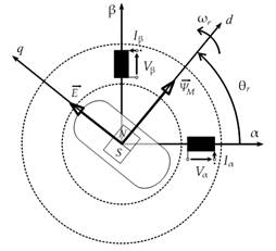 | Figure 1. Back-EMF model in the stator fixed α-β reference |
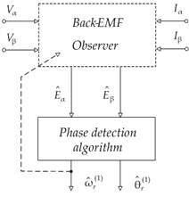 | Figure 2. Back-EMF based sensorless strategy |
Starting from the knowledge of the feeding voltages Vα, Vβ and currents Iα, Iβ, a model-based state-observer is used to estimate the motor back-EMF components which in turn contain the information on the rotor magnet position and speed according to the following statements: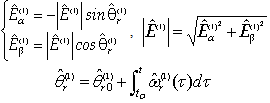 | (1) |
where  represent the sine/cosine estimates of the first order harmonics (denoted with “(1)”) of the motor back-EMF,
  its amplitude,
  the related pulsation and phase angle (i.e. electrical speed and position of the rotor magnet axis), and the initial value of this last, respectively.In order to complete the sensorless strategy, the outputs of the back-EMF observer must be processed by a phase-detection algorithm in order to extract the information of the rotor magnet position and speed. Depending on the observer structure, it could be necessary to provide this last quantity as a feedback signal to the observer itself.
2.2. Motor Modeling
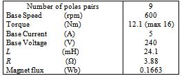
The motor considered in this work, but with no loss of generality with respect to more standard machines, is a five-phase surface mounted permanent magnet synchronous motor (SPMSM) suitable to be used in avionic applications where phase redundancy is a strict requirement in order to have a high reliability[3]. The interest in taking such a kind of motor as a case study consists in the fact that this machine, used in safety-critical applications, demands a sensorless strategy and moreover it is suitable to highlight most of the side-effects, due to the implementation knots, originating the second foremost issue we introduced in section 1. In addition to this, even though this type of machine has a good reliability due to phase redundance, on the other hand, it has no fault-tolerant capabilities with respect to position information: the sensorless control feature could resolve this lack. In particular, it has 18 rotor poles and 20 stator slots (4 slots per phase); each phase consists of two series coils mounted on diametrically displaced stator teeth (parameters such as phase resistance R and inductance L are listed in table I). Due to this structure, independent feeding of each phase is provided by independent H-bridges modules[9].In order to set-up the sensorless strategy we have to first develop for this motor an equivalent two-phase representation. Starting from a five-phase representation stated by: | (2) |
where the subscipt x indicates each phase (x=A,B,C,D,E) and we have generalized the back-EMF dependence from the angular position through specific shape functions defined by: | (3) |
So,we can move to an equivalent stationary two-phase reference frame using a properly designed linear operator defined in our case by the following transformation matrix: | (4) |
which allows to represents the five-phase motor by a couple of space-vectors with components denoted as  and
and  plus an homopolar component. In the following, to the aim of sensorless control, we will consider only the direct sequence components for the set-up of the observer-based sensorless strategy. In fact, the information on the rotor position can be extracted also considering the first harmonic of the direct sequence component only.The shape functions of the motor considered in this paper are reported in Fig. 3: they have a “quasi-trapezoidal” shape, while the electrical parameters are reported in Table I.
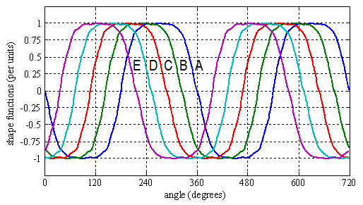 | Figure 3. Back-EMF shape functions of the five-phase motor (design data). |
Considering the equivalent two-phase stator-fixed model associated to the direct sequence space-vector of the five-phase motor, the following state equation is obtained: | (5) |
where: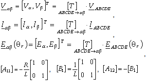 are denoting system vectors and matrices of parameters.According to (1), the rotor (magnet) position information is contained in the sine/cosine shapes of the 1st harmonic back-EMFs. If the speed is assumed as a constant (that is the case of speed steady-state operation), the following relations are achieved by time derivatives of these fundamentals:
 | (6) |
being: | (7) |
a speed dependent matrix.By associating (5) and (6) the following "extended model" is obtained, which represents the motor dynamics in terms of 1st harmonics back-EMFs at speed steady-state: | (8) |
with  indicating state variables, and:
 the system's dynamic matrices. In the extended model (8) the currents acts as the system outputs (measurable state-variables), the applied voltages are the system inputs, while the back-EMF components take the role of internal (non measurable) state-variables.
2.3. Back-EMF Observer Construction
Starting from the previously described motor model, a Luenberger-like observer has been constructed, capable to track the run-time waveforms of the motor back-EMFs. Then the position and speed information can be properly extracted through the use of a phase-detection algorithm. It must be noticed that due to the dependence of the observer sub-matrix  from the rotor speed, the estimate of this quantity must be used as an additional run-time input of the observer. Hence, the differential equations describing the back-EMF observer block of the estimator presented in Fig. 2 can be stated as follows:
 | (9) |
where  is the vector of the estimated state variables, and
 are the gain matrices (with k1 and g constant gains), and g means for a generic proportionality factor used to weight the back-EMF estimates more than the current ones.
2.4. Overall Sensorless Control Strategy
The drive scheme incorporating the observer-based sensorless strategy is shown in Fig. 4. It represents a classical control scheme of a current regulated PM synchronous motor extended to an Nph-phase motor (in this case Nph=5), where the mechanical transducer has been substituted by an estimation algorithm having the internal structure reported in Fig. 2, fed through proper Nphtoαβ transformations of the input voltages and currents. According to the selected control strategy (field oriented or brushless DC), a certain number of current references and feedback are generated, depending on the estimated position and measured currents.In each current loop a comparison between reference and feedback current is performed, the error is PI regulated and then the correction is applied through the electronic modules present inside the Voltage Source PWM inverter. An external loop regulates the speed through a further PI controller and hence the torque requirement proportional to the current references is generated. | Figure 4. Drive scheme with the sensorless strategy |
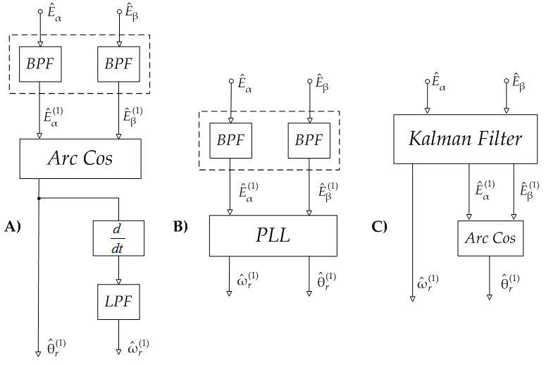 | Figure 5. Phase detection schemes: a) inverse trigonometric function; b) Phase-locked loop; c) Kalman filter |
3. Standard Phase-Detection Algorithms
As already said, the global structure of the sensorless approach is composed by a two-stage scheme: a back-EMF observer plus a phase-detection device in cascade. Hence, in order to obtain the best results it is necessary to optimize not only the response of the back-EMF estimator by tuning the observer parameters but also the phase angle extraction procedure with respect to the needing of fast dynamical response and stability. Thus, cause of the important role covered by the phase-detection algorithm inside the estimation process it has to be highlighted that different algorithms have been developed in literature for optimization purposes, each one carrying out its specific features. So, in order to better understand what are the main performances already offered by the existing algorithms and what could be the improvements still to be done at this level, an overview of the main types of phase-detection algorithms has to be introduced. In this case the three major kinds of phase-detection algorithms are evaluated, Fig. 5: the first one refers to the straightforward use of an inverse trigonometric function; the second consists in a quadrature Phase Locked Loop (PLL) principle; the third one is based on an extended Kalman filter (EKF) for a noisy sin/cos model.
3.1. Rotor speed and position detection with inverse trigonometric functions
According to the relations (1) presented before, we have: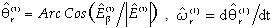 | (10) |
This is a straightforward method to compute the phase angle which assumes that the estimated back-EMF components have purely sin/cos shapes. Such computation requires the preliminary calculation of the back-EMF amplitude and it falls in defect when this assumes very low values. These aspects must be accounted for the implementation, where a further critical point is related to the speed calculation implemented as the angle time-derivative (incremental ratio in a discrete environment), which can lead to use an output Low Pass Filter (LPF). The advantage of this method is that the angle extraction of the position information from the back-EMF waveform is instantaneous and the computational requirement is reduced. The occurrence of not purely sin/cos shapes or additive offsets can be overcome by proper Band Pass Filtering (BPF) of the input back-EMF waveforms.
3.2. Rotor speed and position detection with the standard PLL algorithm
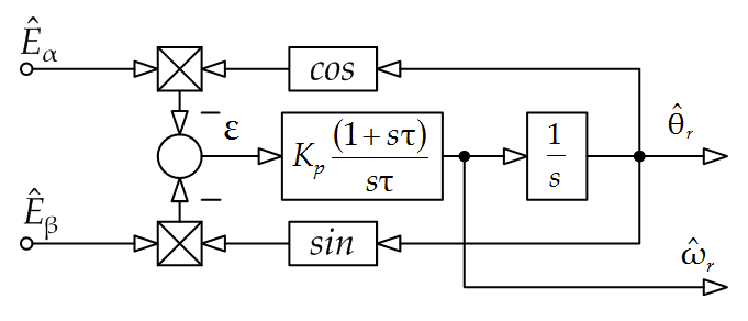 | Figure 6. Standard Phase Locked Loop block scheme |
The basic principle of this algorithm refers to something similar to a quadrature phase detector and involves the generation of an error signal from the phase difference between a couple of quadrature harmonic input signals and the corresponding quadrature feedback functions of the estimated angle. The block scheme of this algorithm is shown in Fig. 6. The error signal (denoted with ε) is corrected through a Proportional Integral (PI) regulator to provide the estimated speed  , and, subsequently to a further integration, the estimated phase angle
  .Assuming for the estimated first harmonics of the back-EMF the relationships:
 | (11) |
where  represents the back-EMF constant and
  the pulsation and phase angle of the estimated waveforms, using the trigonometry subtraction theorems we can write the following analytical expression of the error signal:
 | (12) |
In this relationship  represents thence the argument of the input waveforms (assumed as input references) while
  is the argument of the feedback signals, i.e. the estimated angle. For small deviations between them we can approximate the error as
  and use it to force the time evolution of the estimated angle to converge to the actual one. This can be done by a proper design of the PI regulator, for instance following the approach suggested in [10]. To this purpose one should notice that the error (12) is proportional to the pulsation (i.e. to the motor speed): hence, in order to assure the same response at different speed levels the PI gains should vary with the speed or, alternatively, the input waveforms should be normalized with respect to their amplitude. Moreover, due to the sine dependence of the error signal from the phase difference, one must account that the algorithm can converge to
  . As in the case of the ArcCos function, the occurrence of not purely sin/cos shapes or additive offsets can be overcome by proper Band Pass Filtering (BPF) of the input back-EMF waveforms
3.3. Speed and position detection by Extended Kalman filtering
Another good approach to extract the angular information from the back-EMF waveforms can be the implementation of a Kalman filter that is in practice a state estimator which takes into account also the statistical properties of the noise affecting the state-space model under consideration.It can be successfully used as an alternative way to track the rotor position and speed starting from the back-EMF estimates produced by the observer with more robustness. Due to the intrinsic properties of the EKF algorithm we can expect that the angular information obtained in this manner should be less affected by the disturbances additionally present inside the input waveforms leading to more accurate estimates. By assuming the quadrature inputs as the components of a vector rotating at constant speed, the equations characterizing the model of the proposed Kalman filter in the discretized domain are the following: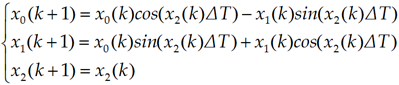 | (13) |
where, assuming to normalize the observed back-EMFs waveforms with respect to their amplitude, we have defined:  ,
, ,
, (
( ;
; ) and where ΔT stands for the sampling time interval. Through the definition of
  we can also state the equations of the model as follows:
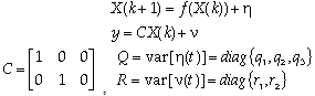 | (14) |
where η and ν stands for the disturbances affecting the noisy sin/cos model describing the back-EMF coming from the observer and entering the phase-detection algorithm, while the symbol f indicates a nonlinear function of the state variables. In this case, the occurrence of not purely sin/cos shapes or additive offsets can be overcome by the filtering properties of the algorithm itself without additional filters.
4. Analysis of the Standard Algorithms
As already said in the introduction, in order to understand what are the main features and the limitations of the still existing phase-detection algorithms, it is necessary to preliminarly compare the performances offered by the standard schemes presented in the previous section; in particular testing them when they are working in a "stand-alone mode", meaning they are running in parallel to the usual control loop of the drive but without acting as a feedback information.This testing mode aims to the study of the behaviour of the phase detection algorithms only, so we can evaluate their performance without the influence of the feedback loops acting through the back-EMF observer and the drive itself. To realize this test condition the estimated back-EMF signals have been properly emulated, using sin/cos approximation, in order to reproduce the actual drive operating condition. As an initial step, the proposed testings are implemented by PC simulations, while in the experimental results they will be implemented using a proper Real-Time Simulation platform.
4.1. "Stand-Alone" Testing Results
The algorithms presented in section 3 were preliminarily tested using a Matlab/SimulinkTM simulation scheme in order to verify their theoretical stationary and dynamic features, but in a stand-alone mode, i.e. without the influence of the back-EMF observer. In this case the inputs of the algorithms (instead of the estimated back-EMF α-β waveforms) consist of a sine wave and a cosine wave modulated in frequency by the amplitude of the ramp signal used as set-point. The related pulsation is called in the following “reference speed”.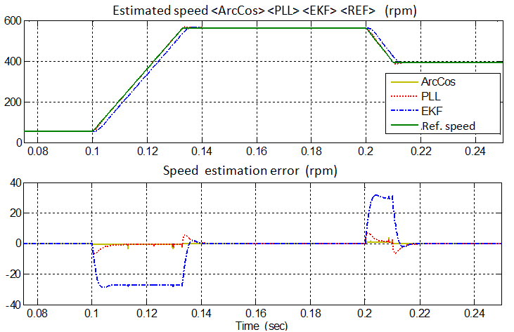 | Figure 7. Stand-alone testing: speed estimates obtained with the three different algorithms working in parallel during an up speed ramp from 60 to 565 rpm and subsequent down ramp reduction to 400 rpm |
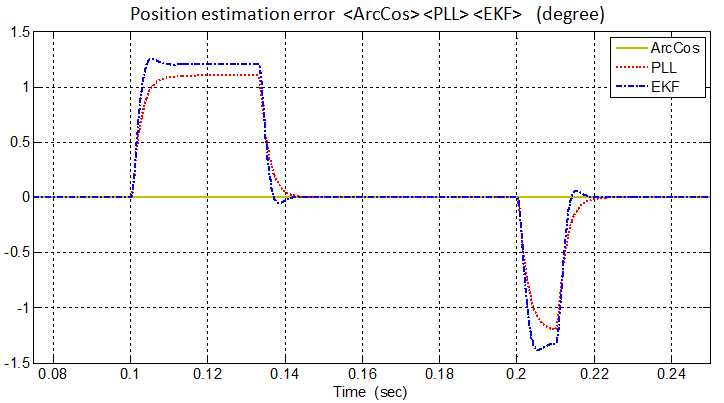 | Figure 8. PC simulation-ideal operation: position estimation errors obtained with the three different algorithms working in parallel during a speed ramp (up) from 60 to 565 rpm and subsequent ramp (down) reduction to 400 rpm |
The operating conditions are selected referring to the actual 5-phase brushless DC controlled motor featuring 58.3 Vpk back-EMF @565 rpm (assumed as rated speed conditions) [8]. The testing condition refers to an up speed ramp with 30 pu/s slope from 60 to 565 rpm, and a subsequent ramp (or step) reduction to 400 rpm (a starting speed different from zero is considered to avoid taking care of algorithm's initialization transients). A digital implementation is assumed for all the algorithms with a sampling time of 200μs. In this first case study the algorithms operate under ideal sinusoidal conditions for the input back-EMF α-β components. The three different phase detection algorithms exhibits the responses reported in Fig. 7 and Fig. 8. With the assumed parameters (see Table II), the PLL has a faster response and lower peak position error than the EKF algorithm, while the ArcCos has the better (almost ideal) response. Moreover, the EKF presents a constant speed estimation error during the speed ramp transients (i.e. at constant acceleration), related to the hypothesis assumed in its development, which is not present when using the PLL.
5. The Speed-Reversal Issue
As already said in the introduction, despite to the quite good features showed by the three standard algorithms (at least in ideal conditions), analysed in detail in the preceding section either under stand-alone testing conditions (meaning almost ideal conditions) or under drive-operating testing conditions (meaning the real operating conditions, where also some kinds of non-idealities have been considered), there exists a relevant structural problem that limits anyway the applicability of the canonical algorithms in the overall speed range. For the sake of completeness it has to be said, in fact, that all these standard phase-detection principles fall in defect when they are operated under speed reversals.This is due to the fact that the development process of all the enumerated standard algorithms is mainly based on a back-EMF model that is valid only in the positive speed range but that does not hold in the opposite speed region.In particular, the relationship stated in (1) can be used formally only for the positive rotation sense, referring this way the back-EMF model to the following shape functions: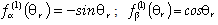 | (15) |
but for the negative sense it must be highlighted that the shape functions must be changed into the following ones: | (16) |
Even though the stationary model of the back-EMF assumes anyway the following statement (considering the speed with the correct sign):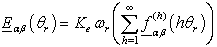 | (17) |
the final effect consists in the switching of the signs of the shape functions that badly reflects on the position estimation error characterizing the three standard algorithms.This is due to the fact that using anyone of the standard principle schemes presented in Fig. 5, for instance the PLL, once the designer has set the parameters of the algorithm (in this case the gains of the PI regulator and the coefficient of the integration block), the estimates produced by the standard PLL are good only in the same rotation direction, otherwise the estimated position will be affected by an error of 180 degrees. In fact the system resulting from the adoption of this specific algorithm has two equilibrium points (as already known by literature) one for 0 degrees and another one for 180 degrees of position estimation error.It must be paid attention that when the drive operates in the same rotation sense for which the gains have been set, the equilibrium point in zero is a stable focus, as can be seen from the following picture, whereas the other equilibrium point has a saddle node nature that implies no convergence to it in practice. Figure 9 shows the position/speed error phase-portrait of the standard scheme for positive speeds. This can be showed analytically by writing the differential equations describing the PLL error system: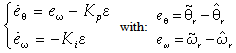 | (18) |
where the variables eθ and eω account for position and speed estimation errors, and where the hypothesis of  has been done. The equilibrium points are determined by (eθ ,eω) = (± kπ,0) with k = 0,1,,∞. When the speed reversal happens, the sign of the back-EMF signals changes and the same sign inversion will be found on the error expression, driving the phase-detection algorithm to converge to the equilibrium point at 180°, missing this way the correct polarity information. In this case the overall properties of the equilibrium points are illustrated by the new phase-portrait of Fig. 10 where we can see that a bifurcation happened: the saddle nodes have changed into stable focuses and the stable focus has changed into a saddle node equilibrium point.
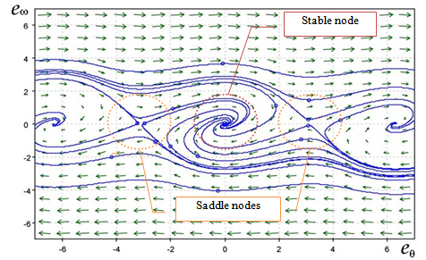 | Figure 9. Phase-portrait of the standard PLL (positive speeds) |
 | Figure 10. Phase-portrait of the standard PLL (negative speeds) |
This implies that when the speed reversal happens the trajectory of the PLL system will diverge from the origin to reach the equilibrium points at 180 degrees of position error. One practical way to solve this problem can be the scheduling of the values of the PI regulators as a function of the sign of the estimated speed but this could become a difficult situation to be managed since the speed information must be estimated by the PLL algorithm itself, this remedial strategy is not robust because can easily bring to high frequency chattering issues. The aim of this paper is to search for a more robust solution to the problem.
6. The “Extended PLL” Algorithm
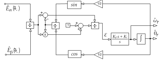
The PLL scheme proposed in this paper is based on a scheme similar in structure to the standard one but with a particular form of the error signal, which constitutes one of the improvements with respect to the more standard PLLs: | (19) |
The proposed function offers also a greater sensitivity of the control action with respect to the values assumed by the position error. Moreover, feedback signals are decoupled from the input ones and the error function has a lower variability with respect to contemporary changes of the signs of inputs. By re-writing the tangent term through the subtraction theorem, the error signal can be arranged as follows: | (20) |
and the PLL scheme assumes the structure shown in Fig. 11 where the PI block acts as in the standard scheme.It should be noted that the estimated quantities produced by this algorithm are not the actual speed and position but their double values, in fact the system reaches its equilibrium point when the following condition holds (i.e. null error): | (21) |
Thus, the estimated angle is equal to twice the actual one, but this does not constitute a problem for the overall sensorless strategy because the actual values can be obtained introducing a simple scaling factor.
6.1. Structural properties of the proposed PLL scheme
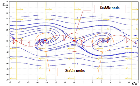
As just aforementioned in the previous sections an alternative PLL scheme should possess better properties with respect to changes of the shape functions in order to exhibit a more robust behavior during speed reversals without having to manage difficult gain scheduling problems at run-time.Thanks to its structure, the proposed scheme robustly overcomes those limitations: the signs of the shape functions have no effects on the sign of the error function. This means that we have to take into account only the dynamical features designed for one sense of rotation, in this case the positive. Moreover, as shown in the error system's phase-portrait of the proposed scheme in Fig. 12, it has only stable focuses (with stable values of the PI gains). Hence, also during inverse rotations, the PLL evolves toward the stable equilibrium points and thus toward the null position error when it is in the phase-locked state. Changes in the speed sign will not affect this phase-portrait at all, since analitically we have: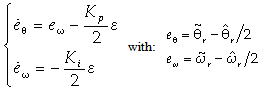 | (22) |
 | Figure 11. Proposed PLL block scheme |
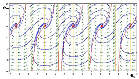 | Figure 12. Phase-portrait of the proposed PLL (positive/negative speeds) |
7. Analysis of the “Extended PLL”
This section aims to analyse the effectiveness of the proposed algorithm through the analysis of its dynamic performances, as already done for the standard algorithms, but considering also the speed reversals. In order to obtain relevant results some simulations using Simulink have been developed arranging in this case two modes of operations, in which the new PLL and the standard PLL have been tested, since this last one has been selected as a representative of the classic schemes. The first testing mode refers to the already introduced "stand-alone" mode, the second testing mode refers to the study of the phase detection algorithms when they are included inside the overall drive control loop incorporating the observer-based sensorless strategy but working off-line with respect to the drive control action. This means that the algorithms are fed using the back-EMF signals produced by the observer and not some test signals.
7.1. PLL algorithms “stand-alone” testing
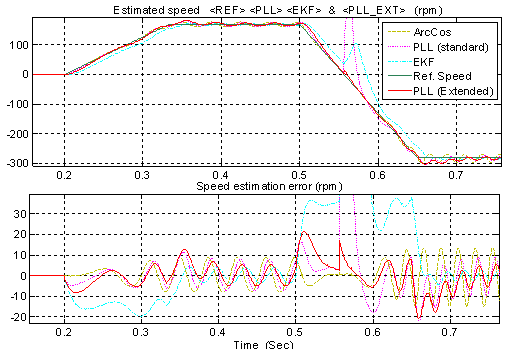
A set of test signals has been generated reproducing a speed transient of the real drive from positive to negative speeds; in particular it leads to get the alpha-beta back-EMF waveforms that are depicted in the underlying Fig. 13.These two waveforms correspond to an up speed transient from 0 to 1 per unit which is followed, after a brief speed steady-state, by a down speed ramp from 1 to -1 per unit under no load conditions. The two algorithms were designed in order to make them comparable, in particular the parameters used in the two PI regulators have been fixed to the discrete–time equivalent gains Kp(disc) =0.3787, Ki(disc)=0.0028.The responses of the two algorithms fed by the aforementioned test signals are reported into the following figures. First, the speed estimation is reported in Fig. 14 while the corresponding position estimation behaviour is reported in Fig. 15; it can be said that we obtain a satisfactory dynamical estimation behaviour only in the case of the new PLL.
7.2. PLL algorithms “drive-operating” testing
The same two PLL algorithms have been tested also when they are operating with input signals given by the estimated alpha-beta components of the back-EMF, obtained using the alpha-beta observer working offline in the control loop of the sensorless drive (that means the estimator is running but the speed and position estimates are not used to control the drive itself). For this reasons the two PLL algorithms are fed in parallel with the same estimated back-EMF signals coming from the state observer and then the estimated quantities are compared. In this test case the operating conditions are maintained similar to the stand-alone testing mode and so the drive is operated using a speed profile equivalent to the one used in the stand-alone test case (but with different duration and slope) and with equivalent values of the PI regulators that in this case are also implemented in the discrete domain in order to keep a good correspondence with the real drive.The behaviours obtained in this case for the estimated speed and position using the two phase-detection algorithms (with gains equal to Kp = 0.55 and Ki = 0.01) in cascade to the back-EMF observer (with gains equal to K1 = 1.7 and K2 = -1.19) can be resumed by the pictures presented in Fig. 16. and Fig. 17. respectively for speed and position estimation.The new PLL scheme has a much better behaviour during the speed reversal and it does not miss the correct polarity.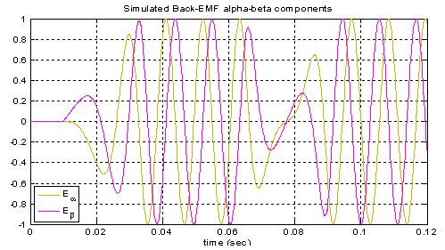 | Figure 13. Simulated back-EMF components reproducing the estimated components during a speed reversal from 1 to -1 pu |
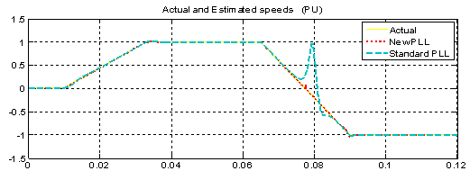 | Figure 14. Speed estimation using the two PLL algorithms during a simulated speed transient from 0 to 1 pu and from 1 to -1 pu and relative speed estimation errors |
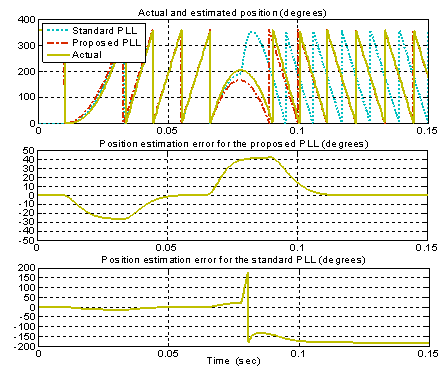 | Figure 15. Position estimation using the two PLL algorithms during simulated speed transients from 0 to 1 pu and from 1 to -1 pu with relative errors |
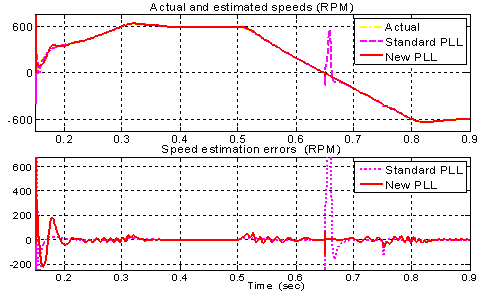 | Figure 16. Speed estimation using the two PLL algorithms and relative speed estimation errors during a simulated speed reversal of the drive with no load and when the estimator operates offline in the control loop |
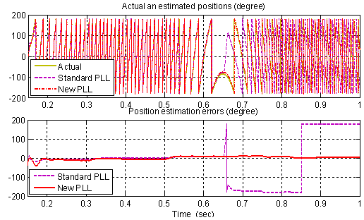 | Figure 17. Position estimation using the two PLL algorithms and relative position estimation errors in the same operating conditions of Fig.16 |
8. Robustness Comparative Analysis
Recalling to the two initial major issues presented in the introduction, it can be said that section 4 gives the necessary performance background about the standard algorithms while section 7 illustrates the behaviour of the new PLL algorithm versus one representative of the standard schemes, in particular the PLL, but with respect to the first issue only.Since all the standard algorithms and also the new one must be implemented on a real drive, most of the times the ideal performances could not be ensured cause of the presence of a huge variety of unavoidable side-effects, so it becomes necessary to study the performances of all them from the point of view of disturbance rejection, trying to find a remedial to mitigate the second major issue. In fact, the proper choice of the phase detection algorithm can constitute a useful degree of freedom to ensure robustness with respect to various implementation impairments such as noises, unwanted additive harmonic components, presence of offsets and so on. In order to study the properties of all of them with respect to this topic, that is significant from the point of view of the practical implementation, the robustness analysis reported in this section has been developed.So the basic idea consists in the comparative analysis of all the phase-detection algorithms against a subset of practical implementation knots, in particular introducing the following two types of imperfections on the estimates:1. DC-offsets2. Unwanted harmonic contentsThe reasons which led to identify these two classes of knots can be resumed by the following two main motivations.First, the signals entering the back-EMF observer are inherently affected by the presence of a certain level of DC-offset due in particular to the nature of the current sensors (current offsets) and to the displacement from the zero of the voltage command's mean value (voltage offsets).Second, it has to be taken into account that an additive harmonic content can be present together with the standard first harmonic component upon the back-EMF waveforms and this can bring to a great or low degradation of the overall estimation system's performances. Regarding to this last statement it must be noticed that the “quasi-trapezoidal” shape of motor back-EMFs acts in some sense as an inherent additional harmonic disturbance since the machine evolves using the fundamental excitation plus some slight contributions of 3rd and 5th harmonics. Ultimately, from the preceding two remarks and from the fact that the observer cannot act against them in any way, the final side-effect of these non idealities results in the presence of offsets and spurious harmonics inside the estimated back-EMFs that reflects directly in a distorted reconstructed mechanical information.In order to check the robustness properties of the still existing algorithms and searching for a possible improvement with the extended PLL, the performances of all the detectors have been tested (using the parameters listed in table III) under the next specific non ideal working conditions.
8.1. DC-Offset Rejection Testing
In this test case an additional constant DC-offset has been added to the αinput component and equal to 5% of the rated back-EMF amplitude. Figure 18 and figure 19 report the results obtained simulating these non ideal operating conditions and considering a speed transient starting from 0 and rising to 0.3 pu followed by a speed reversal to -0.5 pu.Cause of the presence of the DC offset we can see that the position estimation error is characterized by an oscillatory pattern. During the transient the error peak value is affected by the dynamics of the algorithm itself so we have a certain excursion that depends on the properties and settings of the algorithms. At speed steady-state the transient error is almost null and the only effect is due to the offset, the new algorithm seems to be slightly less affected by the action of the offset.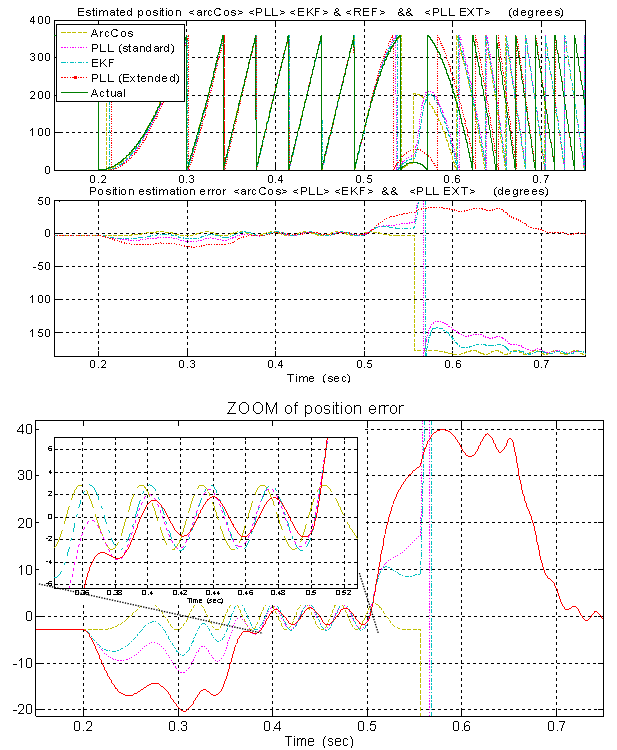 | Figure 18. PC simulation - non ideal operation: position estimates obtained with all the algorithms working in parallel during a speed transient from 0 pu to 0.3 pu and a subsequent speed reversal to -0.5 pu (case of 5% DC offset addition on the α-input) |
 | Figure 19. PC simulation - non ideal operation: speed estimates obtained with all the phase-detection algorithms working in parallel during the same speed transient (including reversal) of Fig. 18 |
8.2. Harmonic Rejection Testing
In this second test case we are going to check the robustness of the examined angle-extraction strategies with respect to the presence of unwanted harmonic contents. This means in other words that we are examining the behaviour of the phase-detection algorithms when they are excited with some test signals reproducing the estimated back-EMF but which are affected by a high level of harmonic distortion added to them. Regarding to the properties of the five-phase sensorless strategy we have developed, this operating condition could represent an unusual situation in practice because the input five-phase transformations can mask the presence of feeding harmonic contents to the observer, in fact the final effect of the constructive/destructive composition of the terms inside the matrix in equation (4) will result in the partial/total cancellation of third and fifth harmonic components. When the case of a not perfect suppression will happen, we can further reduce the effects of the harmonics upon the estimated speed/position acting at the phase-detection level, optimizing the choice of the algorithm used to obtain the position/speed information.The following simulations are built with a relevant level of harmonic content, since we want to emphasize the inherent features of the algorithms. Figures 20 and 21 refer to the addition of a certain level of harmonic components consisting in a 5% of 3th harmonic plus a 2% of 5th harmonic (% referred to the rated back-EMF) in both the α-β inputs. The performances of the proposed PLL seems to be better than the standard one but worse than what exhibited by the EKF, at speed steady-state. During transients instead, the proposed PLL has the largest position estimation error.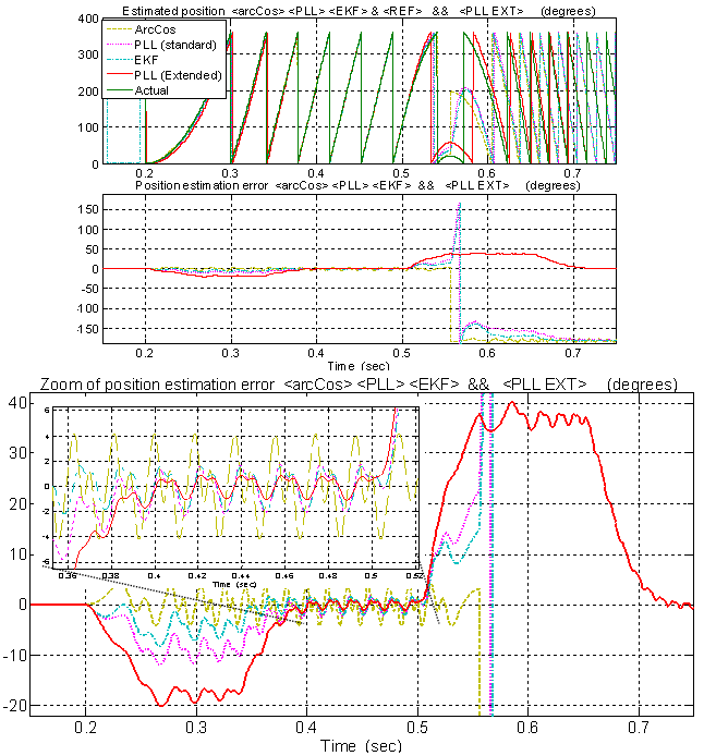 | Figure 20. PC simulation - non ideal operation: position estimates obtained with all the algorithms working in parallel during a speed transient from 0 pu to 0.3 pu and a subsequent speed reversal to -0.5 pu (case of 5% of 3th harmonic plus a 2% of 5th harmonic addition) |
For what concerns with the speed estimation, the proposed algorithm has the best performance either at steady-state (with minimum speed ripple) or during speed transient.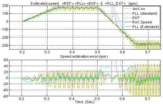 | Figure 21. PC simulation - non ideal operation: speed estimates obtained with all the algorithms working in parallel during the same speed transient of Fig. 20 (case of 5% of 3th harmonic plus a 2% of 5th harmonic addition) |
9. Real-Time Simulation Results
Owing to the aim of confirming also the practical validity of the proposed novel PLL scheme and of the overall sensorless strategy too, some experimental tests have been planned that will use a hardware setup built-up appropriately. The experimental set-up was arranged to verify through the use of a specific Real-Time Simulation (RTS) platform the performances of all the considered phase-detection algorithms with respect to either the speed reversal problem or the robustness against implementative knots. These kinds of simulations can take into account the action of both the back-EMF observer and the motor, simulating the behaviour of this last one through the numerical resolution of the differential equations characterizing the analytical model developed for it. The real-time setup is shown in Fig. 22, while the block scheme reporting its functional structure is illustrated in Fig. 23.It consists of a control unit which is based on a TMS320F2808 digital signal controller (DSC) that enables us to implement the real-time simulation of the motor behaviour, including the control algorithm and the estimation algorithm, in the discrete-time domain with a quite fast computation speed (the interrupt period is equal to 200µs).It includes also a host PC, a digital-to-analog converter (DAC) and a scope. The host PC runs the DSC development environment, the debugger tools and the user interface, the latter allows data exchange with the control firmware. The scope is used for displaying the variables computed by the control algorithm in real-time, through a 4 channel digital-to-analog converter (DAC). The same analyses previously provided by software simulations can be done also experimentally taking care of acquiring the corresponding real-time algorithm's variables. The input signals consist of a sine wave and a cosine wave modulated in frequency by the amplitude of the ramp signal used as set-point, in the case of stand-alone testing, while they are the estimated back-EMF signals at the output of the observer block in the case of drive-operating testing. The parameters used in RTS are equal to the ones used in the preceding section, reporting only simulink results, since they were selected to stress the algorithm's features (Table III).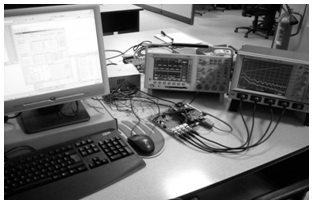 | Figure 22. Real-time simulation set-up |
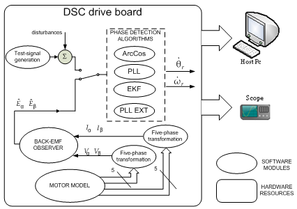 | Figure 23. Real-time simulation block scheme reporting the foremost software modules used to simulate the overall sensorless strategy |
9.1. Stand-alone Testing: Ideal Operation Results
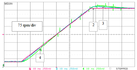
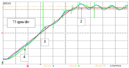
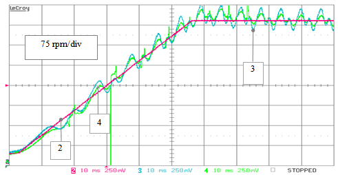
Once again, as a first stage of the analysis, the responses of all the phase-detection algorithms in the ideal operation case have been tested. The results are resumed by the following pictures (figures from 24 to 27), where we can see the behaviour of the standard phase-detection algorithms at first; the reference speed (pulsation of the input back-EMF) and the position estimation errors are depicted during a speed transient from 60 to 565 rpm in Fig.24, and the corresponding speed estimation is displayed in Fig.25. Subsequently, also the behavior of the proposed PLL algorithm versus the standard one has been investigated, under ideal conditions, and the results are reported in Fig. 26 and Fig. 27 for the position and speed estimation respectively.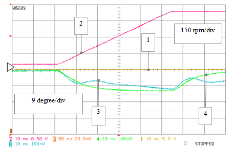 | Figure 24. RTS stand-alone testing - ideal operation: position estimation errors obtained by the ArcCos (track 1), PLL (track 4), and EKF (track 3) algorithms versus the reference speed (track 2) during a speed ramp transient from 60 to 565 rpm |
 | Figure 25. RTS stand-alone testing - ideal operation: speed estimates obtained by the PLL (track 4) and the EKF (track 3) algorithms versus the reference speed (track 2) during a speed ramp transient from 60 to 565 rpm |
 | Figure 26. position estimation errors obtained by the standard PLL (track 3), and by the extended PLL (track 4) algorithms versus the reference speed (track 2) during an analogous speed transient from 60 to 565 rpm |
 | Figure 27. RTS ideal condition test: speed estimates obtained by the standard PLL (track 3) and by the extended PLL (track 4) algorithms versus the reference speed (track 2) during a speed ramp transient from 60 to 565 rpm |
9.2. Stand-alone testing: non-ideal operation results
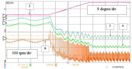
As a second stage we can show the performances under non-ideal operating conditions, in stand-alone mode, highlighting the coherence between the experimental RTS results and the respective ones obtained instead by PC simulations. In particular, as in that case: figures 28 and 29 refer to the addition of a constant DC offset equal to 5% of the rated back-EMF amplitude to the αinput component: these pictures refers to the testing of the standard algorithms only. The testing of the proposed PLL versus the standard one has been done separately but with the same parameters and the results are reported in Fig. 30 and in Fig. 31 respectively.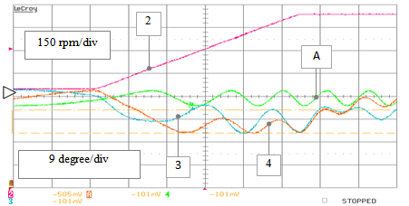 | Figure 28. RTS stand-alone testing – non ideal operation: position estimation errors obtained by the ArcCos (track A), PLL (track 4) and EKF (track 3) algorithms versus the reference speed (track 2) during a speed ramp transient from 60 to 565 rpm (case of 5% DC offset addition on the α-input) |
 | Figure 29. RTS stand-alone testing – non ideal operation: speed estimates obtained by the PLL (track 4) and the EKF (track 3) algorithms versus the reference speed (track 2) during a speed ramp transient from 60 to 565 rpm, (case of 5% DC offset addition on the α-input) |
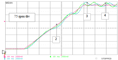
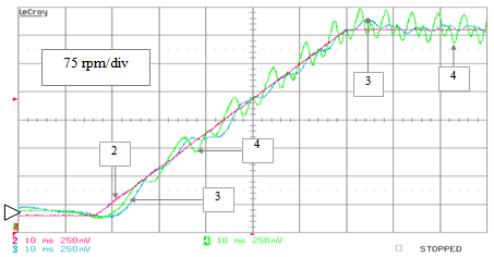
 | Figure 30. RTS stand-alone testing – non ideal operation: position estimation errors obtained by the standard PLL (track 3) and the extended PLL (track 4) algorithms versus the reference speed (track 2) during a speed ramp transient from 60 to 565 rpm (case of 5% DC offset addition on the α-input) |
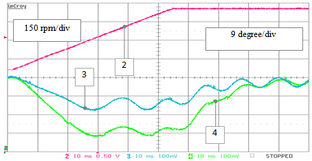
 | Figure 31. RTS stand-alone testing – non ideal operation: speed estimates obtained by the standard PLL (track 3) and the extended PLL (track 4) versus the reference one (track2) during the same speed transient of Fig.30 |
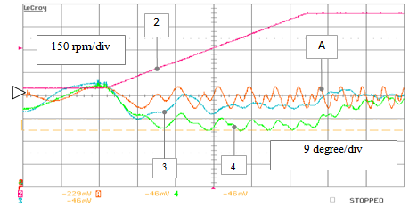 | Figure 32. RTS stand-alone testing – non ideal operation: position estimation errors achieved by the PLL position error (track 4), EKF (track 3) and ArcCos (track A) algorithms versus the reference speed (track 2) during a speed ramp transient from 60 to 565 rpm (case of harmonic disturbance) |
 | Figure 33. RTS stand-alone testing – non ideal operation: speed estimates achieved by the PLL (track 4) and the EKF (track 3) algorithms versus the reference speed (track 2), during a speed ramp transient from 60 to 565 rpm (case of additive harmonic disturbances) |
From here, it can be said that the new PLL possess a greater transient position estimation error even though the effects related to the offsets are smaller at steady-state both in the speed and position estimation. The second stage of the stand-alone testing under non ideal operating conditions is completed by the injection of spurious harmonic content on the exciting signals. Figures 32 and 33 refer to the testing of the standard phase-detectors with the addition of harmonic components consisting in a 5% of 3th harmonic plus a 2% of 5th harmonic (% referred to the rated back-EMF) in both the α-β inputs. In all these cases we do not include pre-filtering of the inputs. The experimental behaviour of the quantities of interest is very close to the ones obtained through the PC simulations during either the up or the down speed ramps.By the comparison of the proposed PLL with the standard one under these operating conditions we obtain the results depicted in Fig. 34 and in Fig. 35, showing that the new PLL is fairly more efficient in case of speed estimation.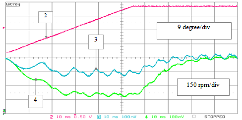 | Figure 34. RTS stand-alone testing – non ideal operation: position estimation errors achieved by the standard PLL (track 3) and by the extended PLL (track 4) algorithms versus the reference speed (track 2) during a speed ramp transient from 60 to 565 rpm (case of harmonic disturbance) |
 | Figure 35. RTS stand-alone testing – non ideal operation: speed estimates achieved by the standard PLL (track 3) and by the extended PLL (track 4) algorithms versus the reference speed (track 2), during a speed ramp transient from 60 to 565 rpm (case of additive harmonic disturbances) |
9.3. Drive-operating Testing and Speed-reversals
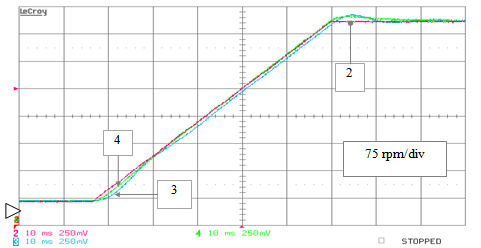
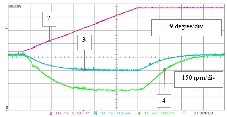
Finally we have to complete the analysis with the behaviour of the full-sensorless strategy taking into account also the effects introduced by the presence of the extern control system of the electrical drive plus the back-EMF observer. These effects are picked out from the real-time simulation of the BLDC control applied on the software-emulated 5-phase permanent magnets motor, in particular this is the situation where the quasi-trapezoidal shapes taken into account for the back-EMF waveforms introduces the harmonic content previously analysed through the corresponding stand-alone Simulink tests or Real-Time simulations. For what concerns with the DC offsets a displacement from the zero value, equal to the 5% of the rated value, has been added on the command αvoltage measurement reproducing the same conditions simulated in the theoretical tests and that can possibly affect the real drive. Differently from the PC simulation, no band-pass filters have been considered for the observer’s outputs. The results obtained for the speed estimates linked to the use of the standard algorithms and for the related position estimation errors are reported in Fig. 37 and Fig. 36, assuming to test the system with an up speed ramp from 60 to 565 rpm at no-load. As shown by the preceding figures it can be highlighted how the position estimation errors, for all the three classic algorithms, are very similar to what obtained from the corresponding Simulink results. In particular from Fig. 36 we can see that a considerable amount of the steady-state error is related with a phase-lag that does not depend from the algorithm itself but it depends from some implementative time-delays. In Fig. 37 the speed estimates generated by the standard PLL and the EKF algorithms respectively are reported versus the reference speed. The EKF performance in this case is better than the PLL.In the end, the behaviour of the proposed extended PLL has been investigated with respect to the standard algorithm, in particular during speed reversal operations. Owing to this aim, the two phase-detectors have been excited using the estimated back-EMF components coming from the state observer and consequently to the imposition of a speed profile consisting in a ramp command from 0.5 to -0.5 pu. The most important results are summarized by the acquisitions in Fig. 38 and in Fig. 39 showing that the extendexd PLL only is capable to track the inversion correctly.Table I. Motor Rated Values and Parameters
 |
| |
|
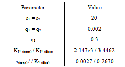
Table II. Parameters Used In The PC Algorithms Simulations (discrete and equivalent continuous values)
 |
| |
|
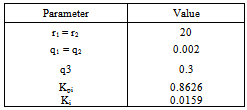
Table III. Parameters Used In The Real-Time Algorithms Simulations (numerical DSP implementation)
 |
| |
|
 | Figure 36. RTS drive-operating testing: position estimation errors produced by the standard PLL (track 4), EKF (track 3) and ArcCos (track A) algorithms versus the actual speed (track 2) during a speed ramp transient from 60 to 565 rpm (with addition of 5% DC offset on the αinput) |
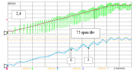 | Figure 37. RTS drive-operating testing: speed estimates produced by the standard PLL (track 4) and EKF (track 3) algorithms versus the actual speed (tracks 2 and C), during an increasing speed ramp transient from 60 to 565 rpm (with addition of 5% DC offset on the αinput) |
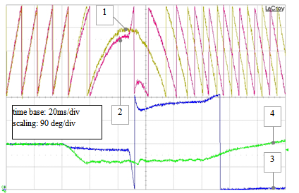 | Figure 38. RTS drive-operating testing: estimated position produced by the standard PLL (track 2) and by the extended PLL (track 1) together with the relative errors: standard PLL position error (track 3) and extended PLL error (track 4), during a speed reversal transient from 0.5 to -0.5 pu |
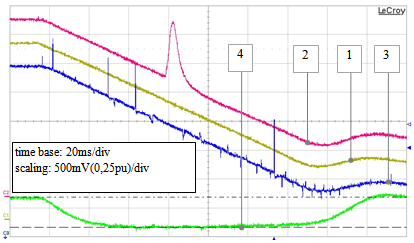 | Figure 39. RTS drive-operating testing: estimated speed produced by the standard PLL (track 2) and by the extended PLL (track 3) algorithms together with the actual drive speed (track 1) and extended PLL error (track 4), during a speed reversal transient from 0.5 to -0.5 pu (scaling 50 ms/div) |
10. Conclusions
In this paper a brief preliminary review of the performances that can be obtained using the standard algorithms for the phase-detection stage of the sensorless drive scheme proposed in Fig. 4 has been presented. These algorithms, known from literature, when applied to such a kind of sensorless strategy suffer of two main criticities not yet completely addressed, that are: structural weakness to motor speed reversals and low disturbance rejection.The main target of the paper is related with the research of a more robust solution to the speed reversal problem and for this reason a novel PLL algorithm, called "extended PLL", is presented in order to fight against this critical issue. As a further working point also the suitability of the new scheme for the solution of the second listed issue has been explored.A fully-detailed analysis has been presented in order to validate the effectiveness of the proposed scheme either from a theoretical point of view, through simulink simulations, or from a practical point of view, through the use of specific hardware real-time simulations. Simulation and experimental RTS results have confirmed the suitability of the "extended PLL" for the implementation of the overall sensorless strategy, in particular exhibiting features showing that the speed reversal issue affecting the standard schemes has been efficiently and robustly solved. As expected, the proposed algorithm does not need to schedule the values of the gains depending on the value of the estimated speed sign. In addition to this, it does not require any normalization procedure in order to adapt the amplitude of the estimated back-EMF signals for maintaining a constant bandwidth. In all the proposed test cases the extended PLL has confirmed the capability to track the real position either during negative/positive speed ramps or during speed reversals, especially without missing the correct polarity information, that is instead an unavoidable problem when using the standard schemes.Furthermore, the novel PLL scheme has been comparatively analyzed with respect to the classical algorithms also from the point of view of the robustness against implementative impairments, in order to accomplish to the second mentioned main problem. From here it can be said that the standard algorithms can ensure quite good responses only under ideal operating conditions. In particular there have been highlighted the negative effects due to the typical knots coming from two major classes of imperfections: DC-offsets and superimposed spurious harmonics. When a DC offset bias one or both the input back-EMF components the estimated speed and position are affected by an unwanted oscillation that increases its peak value according to the level of the input offset, implying a not null estimation error even at steady state when it should be instead theoretically zero. The standard PLL and the ArcCos algorithms feature in this situation quite similar responses, showing that the intrinsic sin/cos design approach of the two algorithms makes their performances very close each other.Analysing the responses to the second type of non-ideality (spurious harmonics) it is important to notice that in this case the best performances are gained by the EKF while the standard PLL is comparable once again to the ArcCos scheme, despite of a greater transient position error ascribable to its dynamic nature. In order to reduce these effects, some additional filters should be taken into account for the standard PLL and the ArcCos algorithms with low-pass filtering features while the EKF will reject these disturbances by itself, implying no need for further filtering actions.On the other hand, the results of the robustness analysis showed that extended PLL possess also from this perspective several advantages with respect to the classical schemes. It results in fact that the effects of DC offsets are reduced as well as the effects due to spurious harmonic contents without introducing any kind of pre-filtering. In conclusion the proposed "extended PLL" scheme offers several interesting advantages with respect to the standard algorithms, owing to the aim of building a sensorless strategy, in particular: a good trade-off between performances and complexity, more robustness to the speed reversal problem, a built-in bandwidth normalization feature plus a fairly lower sensitivity to the real implementation impairments.
References
| [1] | M. Tursini, R. Petrella, A. Scafati: “Speed and position estimation for PM synchronous motor with back-EMF observer”, Conf. Record of the Fourtieth Industry Applications Society Annual Meeting, IAS 2005, Vol. 3, pp: 2083 – 2090 |
| [2] | Joohn-Sheok Kim, Seung-Ki Sul: “High performance PMSM drives without rotational position sensors using reduced order observer”, Conf. Records of the Thirtieth Industry Applications Society Annual Meeting, IAS 1995, Vol. 1, pp 75-82 |
| [3] | L. Parsa, H.A. Toliyat, “Fault-Tolerant Five-Phase permanent magnet motor drives”, Industry Applications Conference, 2004. 39th IAS Annual Meeting. Conference Record of the 2004 IEEE, 3-7 Oct. 2004 Vol.2, pp.1048 - 1054 |
| [4] | G.-C. Hsieh and J. C. Hung: “Phase-locked loop techniques—A survey”, IEEE Trans. Ind. Electron., Vol. 43, pp. 609–615, Dec. 1996. |
| [5] | J.L.Stensby: “Phase-Locked Loops: Theory and Applications”; Boca Raton, FL: CRC Press, 1997 |
| [6] | Lennart Harnefors, Hans-Peter Nee: “A General Algorithm for Speed and Position Estimation of AC Motors,” IEEE Transactions on Industrial Electronics, Vol.47, No 1, 2000 |
| [7] | Vikram Kaura, Vladimir Blasko: “Operation of a Phase Locked Loop System Under Distorted Utility Conditions”, IEEE Transactions on Industry Applications, Vol.33, No. 1, |
| [8] | G. Fabri, C. Olivieri, M. Tursini: “Observer-based sensorless control of a five-phase brushless DC motor”, XIX International Conf. on Electrical Machines, ICEM 2010, pp 1-6. |
| [9] | Thomas M. Jahns, “Improved Reliability in Solid-State AC Drives by Means of Multiple Independent Phase Drive Units”, IEEE Transactions on Industry Applications , Vol. IA-16, 1980, pp. 321 – 331 |
| [10] | R. Petrella, A. Revelant, P. Stocco: “Robust Grid Synchronisation in Three-Phase Distributed Power Generation Systems by Synchronous Reference Frame Pre-Filtering”, Proc. of the 44th Int. Universities Power Engineering Conference, UPEC 2009, Glasgow |
| [11] | Huang, M.C.; Moses, A.J.; Anayi, F.; Yao, X.G., "Reduced-Order Linear Kalman Filter (RLKF) Theory in Application of Sensorless Control for Permanent Magnet Synchronous Motor (PMSM)", 1st IEEE Conference on Industrial Electronics and Applications, 2006 , pp. 1 – 6 |
| [12] | F. Alonge, F. D'Ippolito; "Extended Kalman Filter for sensorless control of induction motors"; Symposium on Sensorless Control for Electrical Drives (SLED), 2010, pp.107–113. |
| [13] | M. Tursini, C. Olivieri, L. Di Leonardo; "Analysis of phase-detection algorithms for back-EMF-based sensorless strategies through real-time simulations"; Symposium on Sensorless Control for Electrical Drives (SLED) 2011, pp. 129-137. |
| [14] | M. Comanescu, T.D. Batzel, “Reduced order observers for rotor position estimation of nonsalient PMSM”, International Electric Machines and drives Conference, 2009. IEMDC '09, 3-6 May 2009 pp. 1346 – 1351 |
| [15] | Preindl, M.; Schaltz, E., "Sensorless Model Predictive Direct Current Control Using Novel Second-Order PLL Observer for PMSM Drive Systems", IEEE Transactions on Industrial Electronics, , Vol. 58 , Issue: 9, 2011 , pp. 4087 – 4095 |
| [16] | C. Olivieri, G. Fabri, M. Tursini, "Sensorless control of five-phase brushless DC motors", First Symposium on Sensorless Control for Electrical Drives (SLED) 2010,pp. 24-31. |
 Abstract
 Reference
 Full-Text PDF
 Full-text HTML