Funso K. Ariyo
Department of Electronic and Electrical Engineering, Obafemi Awolowo University, Ile-Ife, Nigeria
Correspondence to: Funso K. Ariyo, Department of Electronic and Electrical Engineering, Obafemi Awolowo University, Ile-Ife, Nigeria.
| Email: |  |
Copyright © 2012 Scientific & Academic Publishing. All Rights Reserved.
Abstract
The primary purpose in constructing equivalents is to represent a portion of a network containing many buses but having only a few boundary buses by a reduced network containing only the boundary buses and, perhaps, a few selected buses from within the original sub-network. The equivalent constructed gives an exact reproduction of the self and transfer impedances of the external system as seen from its boundary buses. PowerFactory’s network reduction algorithm produces an equivalent representation of the reduced part of the network and calculates its parameters. This equivalent representation is valid for both load flow and short-circuit calculations, including asymmetrical faults (that is, single-phase faults).
Keywords:
Boundary Buses, Reduced Network, Powerfactory, Load Flow, Short-Circuit Calculation
Cite this paper: Funso K. Ariyo, Electrical Network Reduction for Load Flow and Short-Circuit Calculations using PowerFactory Software, Electrical and Electronic Engineering, Vol. 3 No. 1, 2013, pp. 1-7. doi: 10.5923/j.eee.20130301.01.
1. Introduction
A typical application of network reduction is a project where a specific network has to be analyzed, but this network cannot be studied independent of a neighboring network of the same or a higher/lower voltage level. In such cases, one option is to model both networks in detail for calculation purposes. There may, however, be situations when it is not desirable to perform studies with the complete model. Such situations may include, for example, cases when the calculation times would increase significantly or when the data of the neighboring network is confidential and cannot be published in detail. In these cases it is common practice to provide a representation of the neighboring network, which contains the interface nodes (connection points) that may be connected by equivalent impedances and voltage sources[1]. Network reduction for load flow is an algorithm based on sensitivity matrices. The basic idea is that the sensitivities of the equivalent grid, measured at the connection points in the retained grid, must be equal to the sensitivities of the grid that has been reduced. This means that for a given (virtual) set of ΔP and ΔQ (active an reactive power variations) injections in the branches, from the retained grid to the grid to be reduced, the resulting Δu and Δϕ (voltage magnitude and voltage phase angle variations) in the boundary nodes must be the same for the equivalent grid, as those that would have been obtained for the original grid (within a user defined tolerance).Network reduction for short-circuit is an algorithm based on nodal impedance/nodal admittance matrices. The basic idea is that the impedance matrix of the equivalent grid, measured at the connection points in the retained grid, must be equal to the impedance matrix of the grid to be reduced (for the rows and columns that correspond to the boundary nodes). This means that for a given (virtual) additional ΔI injection (variation of current phasor) in the boundary branches, from the retained grid to the grid to be reduced, the resulting Δu in the boundary nodes must be the same for the equivalent grid, as those that would have been obtained for the original grid (within a user defined tolerance). This must be valid for positive sequence, negative sequence, and zero sequence cases, if these are to be considered in the calculation (unbalanced short-circuit equivalent)[1].
2. Methodology
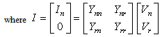
Power system network matrices[2]: | (1) |
where  is the vector of the injected bus currents;
 is the vector of bus voltages measured from the reference node.
  is known as the bus admittance matrix.In a power system, the current injection is always zero at buses where there are no external loads or generators connected; such nodes may be eliminated. Then for an n-bus system, the reduced admittance matrix by eliminating node k is:
 | (2) |
where node k has zero current injection, therefore,  The new bus admittance matrix is:
 | (3) |
where i, j = 1, 2, …, n.  In stability studies, all nodes are eliminated except for the internal generator nodes and obtain the Y matrix for the reduced network:
 | (4) |
 | (5) |
The matrix in equation (5) is the reduced matrix Y. It has dimensions (n x n), where n is the number of generators. Network reduction can be applied only to those nodes that have zero injection current. An equivalent represents a network, which contains many buses but only a few boundary buses, by a reduced network that contains only the boundary buses and a few of the original buses. Equivalents are used in two circumstances: both to allow larger areas of major interconnected systems to be represented in studies and also to achieve improved computational speed in simulations by removing buses and branches that influence system behavior. A boundary cuts a set of tie-lines between areas or otherwise identifiable sections of a network but passes through no buses. A boundary bus is part of only one area. An equivalent makes more efficient use of storage when the ratio of branches to buses in the equivalent is reduced. As a general rule, however, reducing a system into a number of small equivalents is more efficient than reducing of a large system in one step to produce a single equivalent[3-5].
3. Network Modeling in PowerFactory
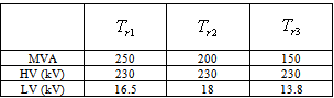
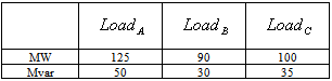
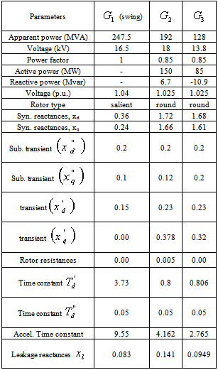
Figure 1 shows IEEE nine-bus system with three synchronous generators. Generator  was selected the swing generator. The transformer, load and generators data are given in Tables 1, 2 and 3 respectively. The network model contains the electrical and graphical information for the grid. To further enhance manageability, this information is split into two subfolders: diagrams and network data. An additional subfolder, Variations, contains all expansion stages for planning purposes. The network model folder contains the all graphical and electrical data which defines the networks and the single line diagrams of the power system under study. This set of data is referred as the network data model.
 Table 1. Transformers data
 |
| |
|
Table 2. Loads data
 |
| |
|
Table 3. Generators data
 |
| |
|
4. Network Reduction in PowerFactory
The Network Reduction function, by default, retains the original network data. The boundary, necessary to split the grid into the part to be reduced, was defined and the part to retain its detailed representation. To ensure that the boundary splits the network into two regions, Check Split button in the ElmBoundary dialogue could be used.The distribution network in Figure 1 is fed by two busbars, ‘Bus 5’ and ‘Bus 6’, in the center of the transmission system. It is represented by Load A and Load B and the corresponding two transformers. If the distribution system is to be studied in details, while the transmission system is to be represented only by its equivalent model. The transmission system has a connection to another transmission system, which is represented by the External Grid and the connecting line. This second transmission system shall remain as it is, the aim of the paper is to reduce only one transmission system. The “Boundary” (shown by dotted line in Figure 1) defines which part shall be reduced[1]. After this, the network is reduced using PowerFactory. The network reduction procedure will automatically create a new variation/system stage to represent the original grid. In the new system stage(s), the part of the grid which was not reduced retains its full representation, whereas the part that was reduced is erased and the new simplified grid representation is added, with the connections to the other part of the grid (that is, to the part which is not reduced). The new system stage(s) will therefore represent the combined grid (retained grid and reduced equivalent). The new system stages will be automatically activated in the active study case. To calculate short-circuit equivalent, this option is used to specify whether the short-circuit equivalent shall be calculated (option enabled) or not (option disabled). PowerFactory currently supports only the complete short-circuit calculation method[1]. Figure 2 shows elements in the defined boundary. These are to be reduced to an equivalent three AC voltage sources (ElmVac) and three common impedances (ElmZpu) connecting the remaining busbars.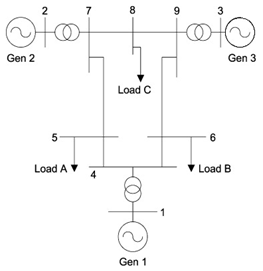 | Figure 1. IEEE three-machine, nine-bus test system[6] |
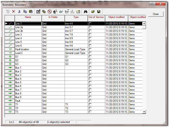 | Figure 2. Elements in the defined boundary |
5. Results and Discussion
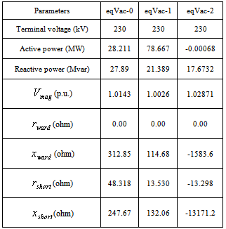
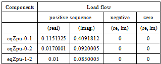
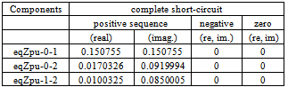
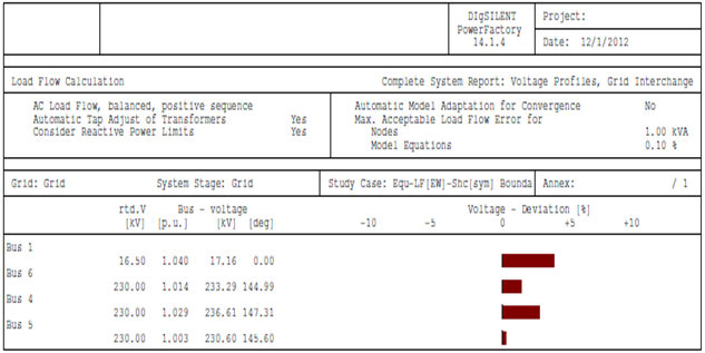
The network reduction was carried out with PowerFactory by DIgSILENT version 14.1[1]. The equivalent model for power injection is extended ward equivalent method. The short-circuit method used is complete method with 0.1 seconds as break time, while the fault clearing time is 1 second.Figures 3 and 4 show PowerFactory command dialogue for AC voltage source and common impedance respectively.The transmission network was reduced to an equivalent representation by three AC voltage sources (eqVac-0 at bus 6; eqVac-1 at bus 5 and eqVac-2 at bus 4) and three common impedances (eqZpu-0-1 between buses 6 and 5; eqZpu-0-2 between buses 6 and 4; eqZpu-1-2 between buses 5 and 4) connecting the remaining busbars. The resulting load flow and method short-circuit parameters are given in Tables 4 - 6.The load flow calculation in the reduced network gives the same results for the distribution network as for the original (non-reduced) network. In Figure 5, the buses 1, 4, 5 and 6 busbars report for the reduced network is the same as the busbars report for buses 1, 4, 5 and 6 for non-reduced network.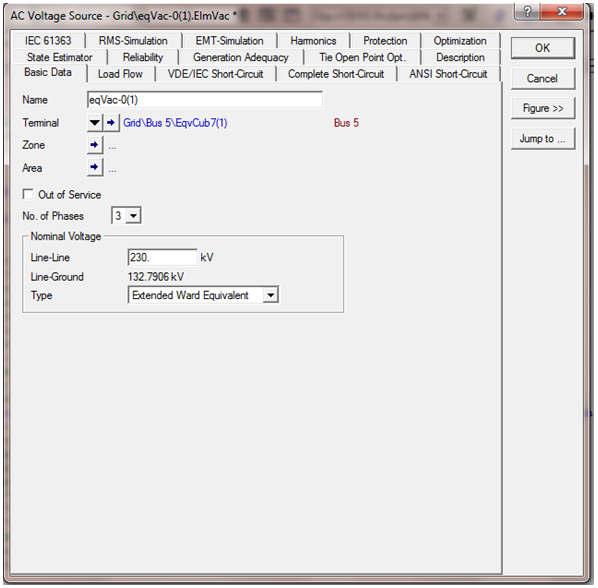 | Figure 3. Command dialogue for AC voltage source |
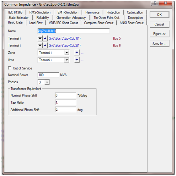 | Figure 4. Command dialogue for common impedance |
Table 4. Parameters of the AC voltage sources
 |
| |
|
Table 5. Parameters of the common impedances (load- flow)
 |
| |
|
Table 6. Parameters of the common impedances (complete short-circuit)
 |
| |
|
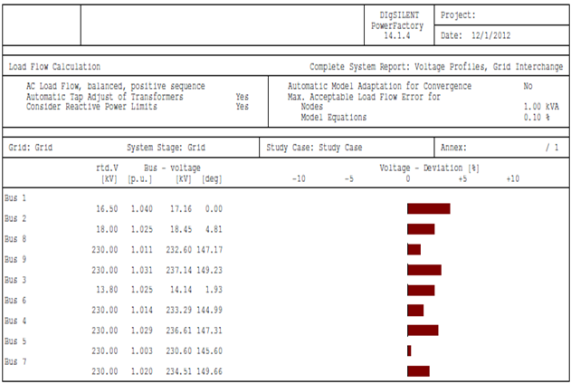 | Figure 5. Load flow (busbars) report for non-reduced network |
 | Figure 6. Load flow (busbars) report for reduced network |
6. Conclusions
PowerFactory’s network reduction algorithm produces an equivalent representation of the reduced part of the network and calculates its parameters. This equivalent representation is valid for both load flow and short-circuits calculations, including asymmetrical faults (that is, single-phase faults). By using small, equivalent networks, the computational requirements can be significantly reduced. Network reduction is usually performed by computing impedances and by eliminating unnecessary elements.This reduction usually results in a highly dense impedance matrix; therefore, using the reduced network may not significantly increase efficiency. Equivalent networks have been used for load flow and short circuit studies because they can reproduce the same voltages and currents of the remaining buses as the original systems do[7]. A load flow calculation or a short-circuit calculation in the reduced network gives the same results for the distribution network as for the original (non-reduced) network.
APPENDIX
Nomenclaturep.u. per unit;HV high voltage;LV low voltage;MW megawatts;Mvar mega volt ampere reactive;kV kilo voltage; voltage magnitude for extended ward method;
 resistance for the extended ward;
 reactance for the extended ward;
 positive-sequence complete short-circuit resistance;
 positive-sequence complete short-circuit reactance;
References
| [1] | DIgSILENT PowerFactory Version 14.1 Tutorial, DIgSILENT GmbH Heinrich-Hertz-StraBe 9, 72810 Gomaringen, Germany, May, 2011. |
| [2] | Saadat, H. ‘Power System Analysis’. McGraw- Hill International Editions, 1999. |
| [3] | P.M. Anderson & A.A. Fouad, ‘Power System Control and Stability’, 2nd edition, IEEE Press Power Engineering Series, Wiley-Interscience, 2003. |
| [4] | Arthur R. Bergen & Vijay Vittal, ‘Power System Analysis’, 2nd edition, Prentice Hall, Inc., 2000. |
| [5] | Yao-nan Yu, ‘Electric Power System Dynamics’, Academic Press, Inc., 1983. |
| [6] | www.sciencedirect.com |
| [7] | Hyungseon Oh, ‘A New Network Reduction Methodology for Power System Planning Studies’, IEEE Transactions on Power Systems, Vol. 25, No. 2, May 2010. |
 Abstract
 Reference
 Full-Text PDF
 Full-text HTML