-
Paper Information
- Next Paper
- Previous Paper
- Paper Submission
-
Journal Information
- About This Journal
- Editorial Board
- Current Issue
- Archive
- Author Guidelines
- Contact Us
Electrical and Electronic Engineering
p-ISSN: 2162-9455 e-ISSN: 2162-8459
2012; 2(6): 374-378
doi: 10.5923/j.eee.20120206.05
A Novel Low Cost Planar RFID Miniature Antenna
 Abstract
 Reference
 Full-Text PDF
 Full-Text HTML
J. Zbitou1, O. Chakkor2, A. Yahya3, A. Tribak4, M. Latrach5
1LITEN, Faculté Polydisciplinaire de KHOURIBGA FPK, université Hassan 1er, Morocco
2ENSA Tetouan. Univ. Abdelmalek Essaadi Tetouan, Morocco
3Faculty of Sciences. Univ. Abdelmalek Essaadi Tetouan, Morocco
4INPT, Groupe d’Electronique et Instrumentation à la faculté des sciences de Tétouan, Morocco
5Ecole supérieure d’Electronique de l’Ouest, BP 30926, 49009 Angers, France
Correspondence to: J. Zbitou, LITEN, Faculté Polydisciplinaire de KHOURIBGA FPK, université Hassan 1er, Morocco.
| Email: |  |
Copyright © 2012 Scientific & Academic Publishing. All Rights Reserved.
This paper presents a new miniature low cost planar RFID antenna designed @ 2.45 GHz. In order to validate the final structure, we have conducted a study on two antenna structures. The first one is based on a rectangular patch with a centred slot line, and the second one is based on a monopole antenna. By comparing the performances of both structures we have chosen the second one because due to the fact that presents a miniature dimensions and especially due to their compactness and robustness against the mechanical tolerances. The antenna achieved and measured demonstrates a good agreement between simulation and measurement results. Moreover, for improving the matching input impedance of the antenna, we have studied and optimized all geometry dimensions of the whole structure. For the feed line we have used a CPW feed which permits to integrate this antenna easily with the memory circuit to form a tag system.
Keywords: RFID, Microstrip Antennas, ISM Band
Cite this paper: J. Zbitou, O. Chakkor, A. Yahya, A. Tribak, M. Latrach, "A Novel Low Cost Planar RFID Miniature Antenna", Electrical and Electronic Engineering, Vol. 2 No. 6, 2012, pp. 374-378. doi: 10.5923/j.eee.20120206.05.
Article Outline
1. Introduction
- The market for radio frequency identification (RFID) technology is growing rapidly. RFID is a method that allows to remotely retrieve, store, and manipulate data contained in a transponder unit that is permanently attached to an object. At present, RFID systems are used in identifying various products, containers and others applications [1],[2],[3],[4],[5]. Examples of applications include: animal tagging, asset tracking, electronic passports, smartcards and shop security. The tag antenna is an essential circuit in passive or active transponders and RFID systems[6],[7],[8],[9],[10],[11],[12]. Therefore it is necessary to match the input impedance of the antenna to a load in order to efficiently couple the RF power. Among The big challenges today considering the applications of the RFID tags which demand a miniature tag system, is to decrease dimensions of the tag by doing a good choice of the architecture of the antenna associated to the chip memory. Among the frequency band for RFID applications we find the ISM” Industrial Scientific Band” at 2.45 GHz[13],[14],[15],[16],[17],[18]. In this work, we have conducted a study of two planar topologies of antennas which can be combined with a microchip to form a tag circuit. Therefore we have optimized the both circuits and compared there performances and dimensions. By the end, we have chosen the miniature structure which is a CPW feed low cost monopole planar antenna.
2. Design and Simulation Procedure
- In this part we will introduce and describe the comparison study of two planar RFID antennas at 2.45 GHz. The aim is to choice by the end a miniature, compact and low cost structure that can be integrated easily to a microchip memory.
2.1. The First structure
- To define the real dimensions of a rectangular patch at 2.45 GHz, we have simulated a rectangular patch, with FR4 as substrate with a thickness of 1.58 mm and 4.4 for the dielectric permittivity. As shown in Figure.1, the dimensions of the antenna are 37.54 mm X 28.12 mm. The Figure.2 presents the return loss of the antenna with a good matching input impedance at 2.45 GHz.In bibliography, many techniques were developed to miniature the tag antennas[19],[20],[21],[22],[23][24],[25]. In this work, we have started this work by developing a new technique to miniature a rectangular patch antenna. As shown in Figure.3, by using ADS “Advanced Design System” we have optimized the dimensions of the patch by introducing a slot line in the antenna structure.Table.1 presents the different dimensions of the new structure. As a conclusion of this first study we can deduce that we have validated a new technique permitting to decrease the RFID antenna dimensions at 2.45 GHz.
|
2.2. The Second Structure
- The final designed antenna structure is based on a CPW feed and a monopole antenna which is presented in Figure.4. After many simulations of the antenna circuit by using ADS optimization method we have validated the final circuit with the dimensions presented in table.2:
|
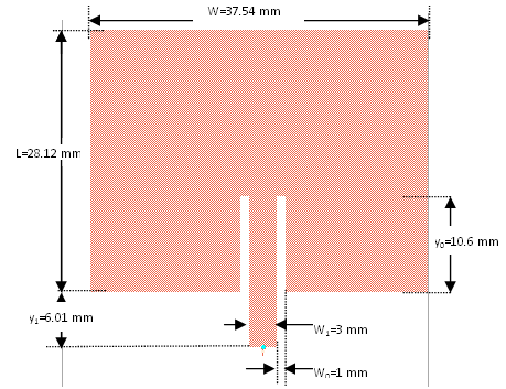 | Figure 1. Rectangular patch structure |
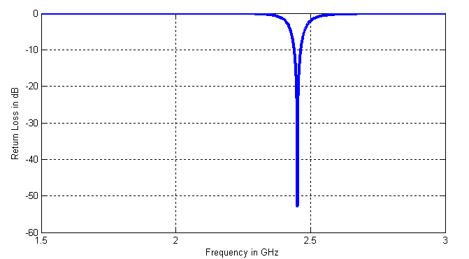 | Figure 2. The return loss of the rectangular patch antenna |
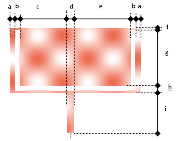 | Figure 3. Rectangular patch structure with a slot line |
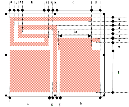 | Figure 4. CPW feed Monopole antenna |
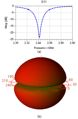 | Figure 5. a- The return loss vs. frequency b- The radiation pattern @ 2.45 GHz |
3. Results and Discussion
- As shown in Figure.7 (a) the antenna was measured by using VNA “vector network analyzer” R&S®ZVB20. When using a VNA to perform antenna measurements, a careful calibration has to be conducted. The reasons are:■ As a radiator, the antenna should not be placed too close to the VNA to avoid coupling and interference, that is, it should not be directly connected to the VNA. Thus, a cable or connectors have to be used.■ The cable and connectors introduce attenuation and a phase shift.■ The reading on the VNA is at the default reference plane, but what we want to measure is the reading at the input port of the antenna.We therefore need to remove the effects of the cable or connectors and shift the measurement reference plane right to the end of the cable. The standard calibration needs three terminations for one-port calibration, i.e. short, open andLoad-matched. The calibration which we have used is the 3.5mm Agilent technologies calibration Kit.Figure.7 (b) shows the simulated and measured return loss results of the antenna which are in agreement. The measured return loss is less than -20 dB at the operating frequency 2.45 GHz.
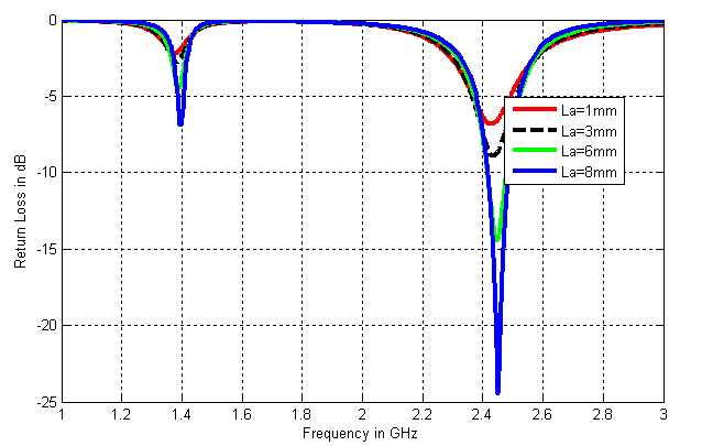 | Figure 6. The influence of La on the return loss |
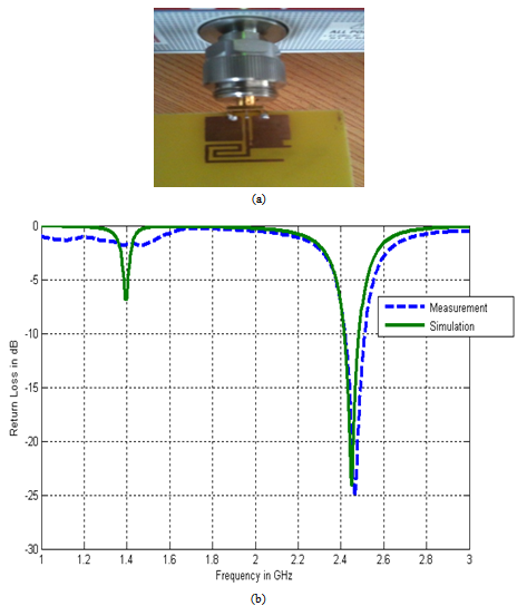 | Figure 7. a. The antenna prototype achieved b. Measured and simulated return loss |
4. Conclusions
- A miniature CPW feed RFID monopole antenna has been developed in the ISM band at an operating frequency equal to 2.45 GHz. Before this validation, we have proposed two studies which describe the methodology and procedure followed to miniature the antenna dimensions. The first antenna validated into simulation can also be used for ISM band applications but taking into account the goal of our work that is the achievement of planar antenna which can be integrated easily with a microchip to form a tag circuit, we have optimized and defined a novel antenna structure. The antenna designed is validated into simulation and measurements after many optimizations that permit to validate a novel RFID miniature low cost planar antenna.