-
Paper Information
- Next Paper
- Previous Paper
- Paper Submission
-
Journal Information
- About This Journal
- Editorial Board
- Current Issue
- Archive
- Author Guidelines
- Contact Us
Electrical and Electronic Engineering
p-ISSN: 2162-9455 e-ISSN: 2162-8459
2012; 2(6): 351-354
doi: 10.5923/j.eee.20120206.02
Design of a Low Noise Amplifire (LNA) with Image Rejection Filter
 Abstract
 Reference
 Full-Text PDF
 Full-Text HTML
Kamran Delfan Hemmati1, Masoud Hojjati2, Mojtaba Behzad Fallah pour3, Abbas Golmakani4
1Pouyandegan e Danesh Institute of Higher Education, Chalus, Iran
2Science and Research Branch, Islamic Azad University, Kerman, Iran
3Young Researcher Club, Lahijan Branch, Islamic Azad University, Lahijan, Iran
4Sadjad Institute of Higher Education, Mashhad, Iran
Correspondence to: Mojtaba Behzad Fallah pour, Young Researcher Club, Lahijan Branch, Islamic Azad University, Lahijan, Iran.
| Email: |  |
Copyright © 2012 Scientific & Academic Publishing. All Rights Reserved.
In this paper we present a new LNA with image rejection filter. Furthermore, after determining topology, we used a suggested multi objective genetic algorithm to optimize the LNA. By performing the algorithm, several results will be obtained as they have no priority to each other, so we can select whichever we want, according to our need. Simulation results show that the suggested plan weakens the image considerably; it also increases LNA gain without changing the noise figure (NF), output matching and input matching. Algorithm program is written by MATLAB and the circuit simulated by Hspice RF with 0.18μ technology.
Keywords: LNA, Image Rejection Filter, Multi Objective Genetic Algorithm, Non Dominated Answers
Cite this paper: Kamran Delfan Hemmati, Masoud Hojjati, Mojtaba Behzad Fallah pour, Abbas Golmakani, "Design of a Low Noise Amplifire (LNA) with Image Rejection Filter", Electrical and Electronic Engineering, Vol. 2 No. 6, 2012, pp. 351-354. doi: 10.5923/j.eee.20120206.02.
Article Outline
1. Introduction
- Low noise amplifiers (LNA) are one of the key building blocks for RF receivers. They play an important role for determining the overall system noise figure (NF) of the receiver. In fact, it used to amplify very weak signals captured by the antenna. It is usually located in the front-end of RF circuits to dominate the system noise by providing a large enough gain. Using a LNA, the effect of noise from subsequent stages of the receive chain is reduced by the gain of the LNA, while the noise of the LNA itself is injected directly into the received signal. Thus, it is necessary for a LNA to boost the desired signal power while adding as little noise and distortion as possible, so that the retrieval of this signal is possible in the later stages in the system. A good LNA has a low NF (like 1dB), a large enough gain (like 20dB) and should have large enough intermodulation and compression point (IP3 and P1dB). Further criteria are operating bandwidth, gain flatness, stability and input and output voltage standing wave ratio (VSWR)[1,2].But there are complicated relations to design LNA circuits. Designing with these relations is difficult and time-consuming, because the relations are approximate. Therefore, a designer must rely on his own knowledge and “tries and errors” methods to obtain desirable results. Here the importance and necessity of using CAD (computer aided design) plays an important role, but computer aided analysis and synthesis tools for RF ICs are still in their infancy which it is forcing the designers to rely on experience, intuition, or inefficient simulation techniques to predict the performance[3,4].In this paper a LNA with image rejection filter is presented, but after determining the circuit structure, finding the appropriate amounts of constituent elements, is high significance although the size of elements can be obtained by using analytical equations but after simulating the circuit with this initial amounts we cannot obtain desirable results; mostly due to the approximate nature of relationship and failure to consider non-linear effects in designing. In this paper, we present a LNA with image rejection filter at first, and after that we use from genetic algorithm to determine the values of the elements So any other calculation is not needed and designer just determines the allowed range of parameter changes to increase the algorithm convergence.This paper is organized as follow: Presenting a LNA with image rejection filter is given in section II. In section III, optimizing multi objective algorithm is presented. Calculation of fitness function and simulation results is presented. In section IV and section V and Finally performance of presented method in this work is compared with previous works.
2. Presenting a LNA with Image Rejection Filter
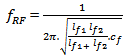
- The usual architecture for RF receivers is heterodyne architecture, which gives us high efficiency and stability. Filtering the image frequency of these receivers is essential; this is usually done by an external SAW (surface acoustic wave) filter. These kinds of filters are big and expensive and incompatible with integration. To overcome this problem, many researches have done. Filtering the image frequency may be done in LNA or before mixer in one or two stages. If we use both of them the image frequency, will be weak. According to “IEEE 802.11a” standard, the amount of the image deletion must be at least 30dB[5-8]. In this suggested plan, the circuit in Fig.1-a is added cascadely to path of the RF signal of a low noise amplifier with a current repeating structure (Fig.1-b), this circuit is made up of a common source and a filter (which allows RF frequency to pass and is open circuit in image frequency). Furthermore the path of DC current for bias gate of the transistor must be established. RF frequency and image frequency of the filter will be obtained from following equations:
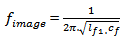 | (1) |
 | (2) |
3. Optimizing Multi Objective Algorithms
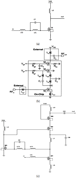
- Most of actual optimizing questions are naturally multi objective. It means that several objects must estimate at the same time. There are two views for solving multi objective optimizing questions. In the first method, we combine objects together, and then give weight to them to change the question to a single objective one. In this condition a certain weight will be given to each objective and objectives with higher priority will be assigned more weight to them. But the problem is that, in actual optimizing questions, objectives have no specific priority to each other. So it is not clear what weight should be allocated to each objective[10,11]. Another method is using of ˝non-dominated˝. In this method, each objective is optimized separately, so that we obtain a bunch of non-dominated answers called ˝pareto optimal answers ˝.None of these answers have any priority to each other, according to all goal functions. So we can select each of them on the basis of our need. multi objective genetic algorithm uses such a technique to optimize multi objective problems .In many of optimizing questions, objectives are in opposition to each other. so the improvement in one may destroy the others. The problem causes the increasing numbers of ˝pareto front ˝after a few repeat. The result of this increasing is disorder in performance of program. To solve this problem, many algorithms have suggested in recent years. In ˝SPEA˝ algorithm, that presented by ˝ Zitzler ˝, the numbers of pareto front preserve in an external archive .there will use of a classification algorithm to reduce numbers of pareto front if the numbers of pareto front cross from distinct border[12,13].
 | Figure 1. a) Suggested amplifier and filter. b) Low noise amplifier with a current repeating structure[9]. c) Suggested LNA circuit with image rejection filter |
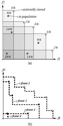 | Figure 2. a) Front of SPEA. b) Front of NSGA-II[12] |
4. Fitness Function Calculation
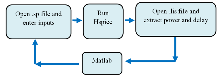 | Figure 3. The circle of Hspice performance with Matlab |
5. Simulation Results
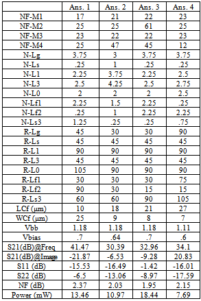
- Using GA program, the circuit size vector and the performance characteristics are shown in Table 1. The answers have not any priority to each other, and designer can select each of them according to his need. Also comparing with previous works is presented in Table 2. Simulation results confirm that; suggested structure weakens the image considerably; it also increases LNA gain without changing the noise figure (NF), output matching and input matching.
|
6. Conclusions
- In this paper, we present a new LNA with image rejection filter. Furthermore, after determining topology, we used multi objective genetic algorithm to optimize structure. So any other calculation is not needed. The answers have not any priority to each other, and designer can select each of them according to his need. Simulation results confirm that; suggested structure weakens the image considerably; it also increases LNA gain without changing the noise figure (NF), output matching and input matching.
References
| [1] | G. A. Golmakani, K. Mafinejad, A. Kouzani,” Design and Optimization of LNA Topologies with Image Rejection Filters”, International Journal of RF and Microwave Computer-Aided Engineering vol. 20, no. 3, pp.289-297, May 2010. |
| [2] | C.-Y. cha, S.-G. Lee, "A 5.2 GHz LNA in 0.35 μm CMOS utilizing inter-stage series response and optimizing the substrate resistance”, IEEE j. Solid-Stage Circuits, vol. 38, no.4, pp.. 669-672, April 2003. |
| [3] | B. Razavi, RF Microelectronics, Prentics-Hall,Upper Saddle River , 1997. |
| [4] | D. Leenaerts, G. Gielen, and R.A. Rutenbar, CAD solutionsand outstanding challenges for mixed-signal and RF ICdesign, Proceedings of the IEEE Conference on Computer-Aided Design, San-Jose, California, 2001, 270–277. |
| [5] | E. Kargarn, H. Khosrowjerdi, K.Ghaffarzadegan and H. Nabovati, "A 5.7 GHz low noise figure ultra high gain CMOS LNA with inter stage technique", IEICE Electronics Express, Vol. 7, no.23,1686-1693. |
| [6] | J.S . Walling, S .Shekhar, and D.J.Allstot, “A gm-Boosted Current-Reuse LNA in 0.18 μm CMOS”, IEEE radio FREQ. Inter.Circuits Symp.,pp . 613-616 ,3-5 June 2007. |
| [7] | Y.S. Wang, L. H. Lu, "5.7 GHz low-power variable-gain LNA in 0.18 μm CMOS", Electron. Lett., vol. 41, pp. 66-68, 2005. |
| [8] | C.-H. Liao, H. R.Chuang, “A 5.7GHz 0.18μm CMOS gain-controlled differential LNA with current reuse for WLAN receiver”, IEEE Microw.Wireless Compon. Lett., vol.13, no.12, pp.526-528, Dec. 2003 . |
| [9] | Choong-Yul Cha and Sang-Gug Lee, “5.2-GHz LNA in 0.35μ CMOS Utilizing Inter-Stage Series Resonance and Optimizing the Substrate Resistance,” IEEE Journal of Solid-state Optimizing the Substrate Resistance,” IEEE Journal of Solid-state Circuits, vol. 38, no. 4, pp.669-672, April 2003. |
| [10] | A.jafari , M.zekri , S.sadri , A.R.mallahzadeh," Design of Analog Integrated circuits by using genetic algorithm" , in IEEE Second International Conference on Computer Engineering and Applications (ICCEA) , pp. 578-581, 2010. |
| [11] | M. Taherzadeh, R. Lotfi, H. Zare and O. Shoaei, "Design optimization of analog integrated circuits using simulation-based genetic algorithm", Proc. IEEE International Symposium on signals and circuits, Vol. 1, pp. 73-76, July 2003. |
| [12] | E. Zitzler, Evolutionary Algorithms for Multiobjective Optimization: Methods and Applications, PhD thesis, Swiss Federal Institute of Technology, Zurich, Switzerland, 1999. |
| [13] | El-Sayed M. El-Alfy, “Flow-Based Path Selection for Internet Traffic Engineering with NSGA-II,” IEEE 17th Internation conferece on Telecommunications, pp. 621 – 627, 2009. |
| [14] | K. Deb, A. Pratap et al, “A fast and elitist multi-objective genetic Algorithm: NSGA-II,” IEEE Trans. On Evolutionary Computation, Vol. 6, no.2, pp.182-197, 2002. |
| [15] | S.Babayan Mashhadi, "Optimizing the Design of Low-voltage and Low- Power Analog Integrated Circuits using Multi-objective Genetic algorithms", A dissertation submitted in partial fulfillment of the requirements For the degree of Master of Science in Electrical Engineering In the graduate division Of the Ferdowsi University of Mashhad. |