Abdul Syakur 1, Hamzah Berahim 2, Tumiran 2, Rochmadi 3
1Ph.D Student at Department of EE & IT, Gadjah Mada University, Yogyakarta, 55281, Indonesia
2Department of Electrical Engineering & Information Technology, Gadjah Mada University, Yogyakarta, 55281, Indonesia
3Department of Chemical Engineering, Gadjah Mada University, Yogyakarta, 55281, Indonesia
Correspondence to: Abdul Syakur , Ph.D Student at Department of EE & IT, Gadjah Mada University, Yogyakarta, 55281, Indonesia.
| Email: |  |
Copyright © 2012 Scientific & Academic Publishing. All Rights Reserved.
Abstract
Polymer insulating materials such as epoxy resin have been using in the distribution and transmission lines as outdoor insulator. Several advantages of using epoxy resin are its low density, better dielectric properties and it has higher volume resistivity than glass and ceramic. However, some weaknesses of epoxy resin are easily influenced by environmental factors such as humidity, ultraviolet radiation, acid rain and effect of contamination. Consequently, surface of insulator will easily damage due to electrical tracking which is indicated by surface tracking. To improve the dielectric properties such as hydrophobic contact angle then silicon rubber was compounded. In this paper to understand of silicon rubber influence on leakage current characteristics and hydrophobic contact angle of epoxy resin insulating materials have been analyzed. The tests were conducted using the Inclined-Planed Tracking (IPT) method according to IEC 60587:1984 standard with Ammonium Chloride (NH4Cl) as contaminant. Flow rate of contaminant was 0.3 ml/min and high voltage AC 3.5 kV 50 Hz was applied to the top electrode. The experimental results reveal that the hydrophobic contact angle, leakage current and surface degradation depend on the composition of silicon rubber. Silicon rubber was improving epoxy resin performance as insulator. Based on analysis it is found that epoxy resin with silicon rubber without silica sand offers the optimum surface tracking and erosion resistance. We conclude that silica sand doesn’t influence on leakage current characteristics.
Keywords:
Leakage Current, Electrical Tracking, Hydrophobic Contact Angle, IEC 60587, Epoxy Resin
Cite this paper:
Abdul Syakur , Hamzah Berahim , Tumiran , Rochmadi , "Hydrophobic Contact Angle and Surface Degradation of Epoxy Resin Compound with Silicon Rubber and Silica", Electrical and Electronic Engineering, Vol. 2 No. 5, 2012, pp. 284-291. doi: 10.5923/j.eee.20120205.07.
1. Introduction
Polymeric insulating materials have been widely used in the distribution and transmission lines for their good dielectric properties, light weight and compact, when compared to the porcelain or glass insulators. When polymeric insulating materials such as epoxy resin used as outdoor insulator showed degradation due to climate stresses such as ultraviolet in sunlight, moisture, temperature, humidity, acid rain and the other contaminants so that the surface discharge, tracking, and erosion can occur, and degradation may reduce the performance. This reduction is actually the result of chemical and physical changes taking place on the surface of polymer[1]. Epoxy resin is an important electrical insulating material. It is a thermoset polymer which two components are mixed to eventually form a glassy product at room temperature. Epoxy resins are used in a large number of fields including surface coatings, adhesives, in potting and encapsulation of electronic components, in tooling, for laminates in flooring and to a small extent in moulding powders and in road surfacing. Compared with the polyesters, epoxy resins generally have better mechanical properties and, using appropriate hardeners, better heat resistance and chemical resistance, in particular, resistance to alkali. The electrical properties of epoxy resins have a dielectric constant about 3.4 – 5.7, and a dielectric strength about 100 – 220 kV/cm. Power factor of epoxy resins are about 0.008 – 0.04[2]. When insulators made of epoxy resin are used outdoor, the presence of contaminants on the surface of the insulator becomes a serious problem. Different materials have different contamination performance. Generally polymeric insulators perform better than ceramics when new. However, due to aging of polymer housing, this relative difference can change along with time at a rate depending on theenvironment[3]. According to Berahim[4], epoxy resin is ahydrophi- lic material, therefore, in particular, in tropical area; humidity, ultraviolet radiation and rainfall play an important role in accelerating of degradation process on the surface of the insulator. Contamination layer will be formed on the surface of the insulator and it would spread on the surface. Surface tracking can occur and lead leakage current increase, especially when the insulator surface wet caused by fog, dew or light rain. Leakage current initiates a process of heat conduction which occurs on the surface of an insulator and finally flashover or insulation breakdown would occur. As we know, silicone rubber (SiR) has the ability to resist water on the surface of the material so that water does not stick. The performance of silicone rubber is very good for insulation. Therefore, silicone rubber is compounded with epoxy resin to improve the performance of epoxy resin surface. Silica sand was added into silicon rubber to reduce composition of silicon rubber. This paper presents influence of silicon rubber and silica on hydrophobic contact angle and surface degradation of epoxy resin using Inclined-plane tracking method according to IEC 60587:1984 standard with Ammonium Chloride (NH4Cl) as contaminant.
2. Fundamental Theory
2.1. Hydrophobic Contact Angle
Hydrophobic property can be observed by measuring water droplet contact angle on the insulator surface. This property is not static, sometime it can be vanished and restored depend on insulator material surface. Hydrophobic property will be restored after 10-12 hours after arc period[7]. This process can be explained by 6 following postulates : 1) Hydrophilic surface reorientation, 2) Polymeric chain migration, 3) loss of oxygen or other polar type to the atmophere, 4) further reaction of polar or other active compound which is blocking chain reorientation, 5) surface roughness change and 6) external insulator surface contamination[8]. In this research, contact anglemeasurement on an insulating material was conducted to determine the surface properties of materials what is hydrophobic or hydrophilic. Hydrophobicity is a characteristic of insulating materials which in polluted conditions, the material is still able to resist water that falls onto the surface. Hydrophobic properties are useful for outdoor insulator because in wet or humid conditions, water continuous flowing between the tip - tip of an insulator will be not formed, and the surface conductivity of insulators will remain low, resulting in very small leakage current. 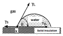 | Figure 1. Contact angle measurement |
Contact angle is the angle formed between the surfaces of the test material with the surface of distilled water that dripped into the test material surface. This measurement uses 50 micro liter droplets of water that is dripped on the surface of an insulating material[4]. Profiles of water droplets were taken after two minutes the water has dripped on the surface of an insulating material. Profile of a drop of water was projected on the screen and the contact angle (180° - γ) could be determined as illustrated in Figure 1. The relationship between surface tension of solid materials, air (gas) and water are shown in Figure 2.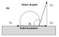 | Figure 2. Illustration of interface tension and equilibrium contact angle |
2.2. Contact Angle Classification
The basic equation for the solid surface tension measurements, by measuring the contact angle is given by Young's equation: | (1) |
Parameters of the Young equation, γSV ,γSI , and γLV are the interface tension of the solid / gas, solid / liquid and liquid / gas respectively, and θe is the equilibrium contact angle. A stable equilibrium is obtained by providing idealsmooth and uniform surfaces. If the surface is rough or heterogeneous, then the system is in a state of unstable and the contact angle measurement is also unstable. In this case the contact angle depends not only on the surface tension but also depends on surface roughness and grain volume of water. Contact angle gives information about the surface energy, hardness, and surface heterogeneity. Moreover the contact angle is also the indication of contaminated surface.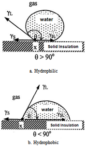 | Figure 3. Classification of contact angle |
Based on Fig 3 above contact angles are classified into two groups. For angles smaller than 90 (Figure 3.a) then the material is called wet or hydrophilic, and the contact angle more than 90o (Figure 3.b) is called the hydrophobic or water-repellent.Material surface wetting by liquid can be explained by DUPRE adhesion energy formula as shown in equation 2.  | (2) |
γLV and γSV are liquid surface energy with air and solid, γSL is interface free enegry of solid and liquid.
2.3. Leakage Current and Surface Degradation
Leakage current is the current that flows through the conductor to ground. In the absence of a grounding connection, it is the current that could flow from any conductive path or the surface of non-conductive parts to ground if a conductive path was available. There are always extraneous currents flowing in the safety ground conductor. If there is no insulation failure, interruption of the leakage currents flowing through the ground conductor could ignored. Leakage current will increase, especially when the insulator surface is wet caused by fog, dew or light rain. Leakage current will initiate a process of heat conduction which occurs on the surface of an insulator and finally flashover or insulation breakdown would occur[4]. The leakage current flowing on the surface of the sample can cause damage. Analysis of surface degradation can be investigated using optical photo graph or surface condition.
3. Experimental Set up
3.1. Materials Preparation and Test Sample
The test materials used in this research were epoxy resins formed from diglycidil ether of bisphenol-A (DGEBA) and metaphenylene-diamine (MPDA) compound with silicon rubber (SiR) and Silica sand. The samples were prepared in the form of blocks with dimension of 50 mm x 120 mm x 6 mm. Test samples must be drilled to place electrodes as illustrated in Figure 4 and 5: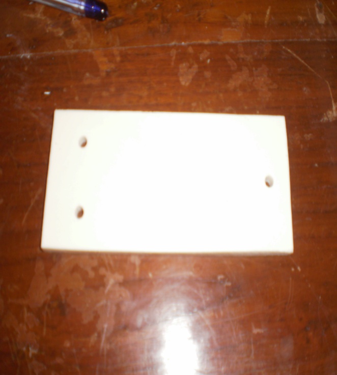 | Figure 4. Physical view of test sample |
Epoxy is a thermosetting chemical compound which is consists of oxygen and carbon chemical bond produced by epichlorohydrin and bisphenol A reaction. Complex structure of Epoxy has molecular epoxy-resin bond shown in Figure 6.Epoxy-resin will be hardened when combined with hardener, catalyst and filler. The application is widely used, such as : insulator, household tools, machinery component, automotive, liquid tank/pipe, aeroplane body material, aerospace component, bridge structure, etc. Epoxy has fine electrical properties : volume resistance (ρ) 1013 – 1015Ωm, dielectric constant (ε) 3.5 - 3.9 (at 50/60 Hz) and power dissipation factor (tan δ) (35-90) x 10-4, but weak against ultraviolet radiation. 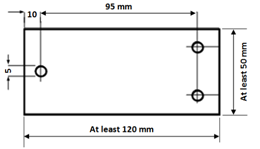 | Figure 5. Schema of test sample and it dimension |
 | Figure 6. Epoxy-resin structure |
Silicon rubber (SiR) is a PDMS which has CH3 as side group. Different chemical compound in every bond will give different property for each polymeric material[8]. Silicon rubber chemical structure has more flexible siloxane backbone compared to other polymeric material. This flexibility advantage can be understanded by chain structure image in Figure 7.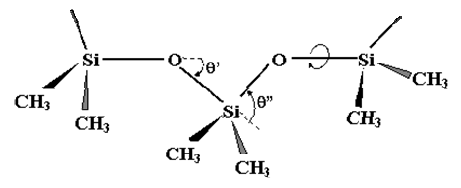 | Figure 7. Silicon rubber chain structure |
Silicon rubber chain structure doesn’t have carbon at the backbone, but present at side group. Those structure show semi-organic structure with high bond energy of S-O which gives very high thermal stability. Eventhough Si-O thermal stability is very good, the ionic property is relatively high which made it easier to be broken by high alkali or acid concentration. Strong Si-O bond gives higher durability for silicon rubber against destruction possibility caused by environment and corona. It also gives same similar property as glass or quartz which don’t cause conductive layer when burned (for example : burned by electrical arc). In the other hand, silicon rubber also has stable elasticity within -50℃ to +230℃ range which is the most important property of electrical insulator material[9]Composition of materials in this research shown in Table 1 as follow:| Table 1. Material composition of polymeric insulators |
| | Sample Code | Composition (%) | | DGEBA | MPDA | SiR | Silica | | RTV01 | 70 | 30 | - | - | | RTV02 | 60 | 40 | - | - | | RTV03 | 50 | 50 | - | - | | RTV12 | 40 | 40 | 20 | - | | RTV13 | 35 | 35 | 30 | - | | RTV14 | 30 | 30 | 40 | - | | RTV22 | 40 | 40 | 10 | 10 | | RTV23 | 35 | 35 | 15 | 15 | | RTV24 | 30 | 30 | 20 | 20 |
|
|
3.2. Electrodes
Electrodes in this experimental, fixtures and assembly elements associated with the electrodes, such as screws, shall be made of stainless steel material. The electrode assembly is shown in Figure 8 (all dimension in mm). The top electrode is shown in Figure 8.a and the bottom electrode is shown in Figure 8.b.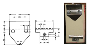 | Figure 8. (a) Top, (b) Bottom (c) electrode assembly |
3.3. Contaminant and Filter Paper
Contaminant used had concentration of 0.1 ± 0.002 % by mass of NH4Cl (ammonium chloride) and its conductivity is 2170 μS/cm. These contaminants were flowed on the surface of materials using a peristaltic pump. There were eight layers of filter-papers as a reservoir for the contaminant, which were clamped between the top electrode and the specimen. The approximate dimensions were given in Figure 9.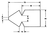 | Figure 9. Filter paper with eight sheets |
3.4. Test Circuit
The system for evaluating the surface tracking of solid polymer insulating materials is shown in Figure 10. The test is based on IEC 60-587 standard method and popularly known as Inclined-Plane Tracking (IPT) test method[5]. AC High voltage 50 Hz with a voltage of 3.5 kV was generated from 5 kVA transformer test. Resistor 22 kΩ was used to resist the current flowing on the surface of the material in the event of discharge. 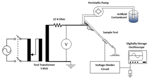 | Figure 10. schematic diagrams for this test |
All the high voltage equipment was properly grounded for safety purpose. Surface tracking was monitored by measuring the surface leakage current (LC) that flows on the material surface. Peristaltic pump was used to drain the solution of contaminants with flow rate was 0.3 ml/min along the underside of the sample. In this test, the constant voltage method was used, 3.5 kV and 50 Hz and the time to start tracking was also determined. Leakage and discharge current will be read and recorded by Oscilloscope in time of discharge at the surface of the material. Measurement data in the form of leakage current was then stored and used to analyze the surface condition for each samples.
4. Result and Analysis
4.1. Hydrophobic Contact Angle
Contact angle measurement on an insulating material was conducted to determine the surface properties of materials (hydrophobic or hydrophilic). Hydrophobic properties are useful for outdoor insulator because in wet or humid conditions, water continuous flowing between the tip - tip of an insulator will be not formed, and the surface conductivity of insulators will remain low, resulting in very small leakage current. 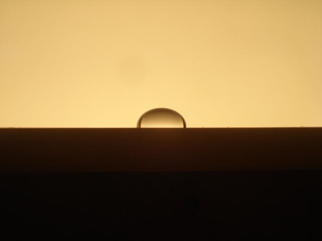 | Figure 11. contact angle of test samples |
Measurements of angle contact were done on samples of epoxy resin without silicon rubber (RTV01, RTV02, RTV03), with silicon rubber (RTV12, RTV13, RTV14) and compound with Silicon Rubber and Silica sand (RTV22, RTV23, RTV24) as shown in the following figure 12 as follow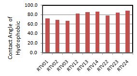 | Figure 12. characteristics of contact angle of test samples |
For contact angles smaller than 90o then the material is wet or hydrophilic, and the contact angle more than 90o is called the hydrophobic or water-repellent. Based on the figure 12 above we know that all samples have contact angle smaller than 90o ( θ < 90o ) it means all samples are hydrophilic.Samples without silicon rubber (RTV01, RTV02 and RTV03) have contact angle smaller than samples with silicon rubber (RTV12, RTV13 and RTV14). Silicon rubber in this case improves the performance of insulator surface. Silicone rubber has the ability to resist water on the surface of the material so that water does not stick[10].
4.2. Leakage Current Characteristics
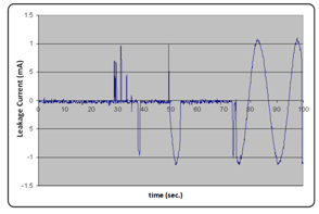
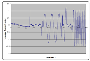
a. Epoxy Resin without Silicon Rubber. The characteristics of leakage current show the material surface condition. One of the parameters that influence the condition of the surface material is hydrophobic properties, where the hydrophobic properties are influenced by the composition of the materials.In this test, process of tracking and erosion is started with the occurrence of surface discharge and flow of current in the surface material. Warming that occurred on the surface of the material is due to the current flowing, and it can cause tracking and erosion. Tracking path the widespread and increasingly longer with the combination of an increasingly conductive surface conditions at the time of contaminant flow in the path already established. Current flowing in the event of surface discharge also increased. The test results of leakage current on samples of epoxy resin with contact angle variation are shown in Fig. 13, 14 and 15 respectively[10]:Based on the characteristics of leakage current shown in Figures 13, 14 and 15 respectively it can be explained as follow: contact angle effect in accelerating the insulation failure is marked by the surface discharge. This can be seen on Figure 15, RTV03 epoxy resin, the flow of NH4Cl contaminants directly lead to the formation of conduction path resulting in discharge on the surface of the path. This is marked by the sinusoidal wave of leakage current. Different phenomena occur in epoxy resin RTV01 and RTV02 (Figures 13 and 14) which requires a longer process to make a complete conduction path from the HV electrode to the earth electrode. b. Epoxy Resin with Silicon Rubber. 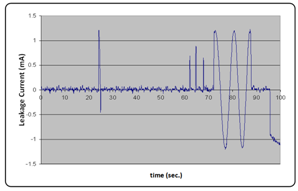 | Figure 13. Characteristic of Leakage Current on RTV01 |
 | Figure 14. Characteristic of Leakage Current on RTV02 |
 | Figure 15. Characteristic of Leakage Current on RTV03 |
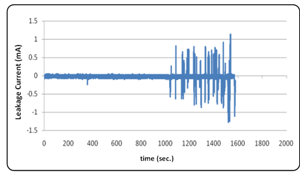
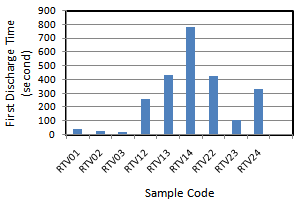
Based on Figures at 16, 17 and 18 it can be explained as follows: tracking time on samples of epoxy resin with silicone rubber filler materials requires a longer time compared with the tracking time in Figures 13, 14, and 15. This indicates that the silicone rubber filler in epoxy resin influence the beginning of tracking time[10]. The leakage current characteristics in the Figures 16, 17 and 18 show that the higher concentration of filler material (silicone rubber), the longer the beginning of time tracking is. This indicates that the sample RTV14 is increasingly hydrophobic. Therefore, the first surface discharge on the surface of the material requires a longer time[6]. Figure 19 shows graphic of first discharge occurred on the surface for each composition. Based on Figure 19 we know that the first discharge is influenced by the composition of the material. Samples without silicon rubber (RTV01, RTV02 and RTV 03) have first discharge time smaller then samples with silicon rubber (RTV12, RTV13 and RTV14). The silicon rubber plays an important role in improving the surface tracking on the surface of polymer materials. At a very high composition of silicone rubber (RTV14), the first discharge is more difficult to occur. It is needed long time (up to ~ 800 sec) to first discharge occur at RTV14. Contaminant on the surface of the material tends to flow without having wetness, so that the surface degradation and carbon formation is continuously prevented [8]. Adding of silica sand to silicon rubber (RTV22, RTV23 and RTV24) tend to decrease first discharge time as shown Figure 19. In this case silica sand significantly influences performance of insulator surface. 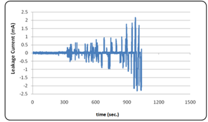 | Figure 16. Characteristic of Leakage Current on RTV12 |
 | Figure 17. Characteristic of Leakage Current on RTV13 |
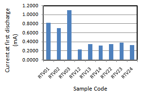
Figure 20 shows the first discharge currents in epoxy resin without silicone rubber, with silicone rubber and silica sand. From the figure 20 we know that the first discharge currents in epoxy resin with silicone rubber is smallest in RTV12. All samples without silicon rubber (RTV01, RTV02 and RTV03) have first discharge current very high compared than samples with silicone rubber and silica sand. Can be concluded that silicone rubber play important roles in this activities.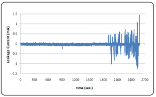 | Figure 18. Characteristic of Leakage Current on RTV14 |
 | Figure 19. The first time discharge for each sample. |
 | Figure 20. Current at the first discharge at each samples |
4.3. Surface Degradation
When AC high voltage is connected to the top electrode, leakage current flows in the conductive path formed by the contaminant (between top and bottom electrode). This leakage current causes non-uniform heating of the surface, thereby forming a dry-band zone in the continuous wet film formed by the contaminant flow, resulting in regions of very high resistivity between the edges of the remaining wet film surface. Electrical tracking on the surface of the material sample is due to heating at the surface of the material at the time of leakage current to flow and once the process of erosion. Leakage current on the surface of the material occurs due to the contaminants that flow on the surface material. Nearly the entire surface voltage (the applied voltage) will appear across the dry band [14].When the air critical flashover voltage was achieved, carbonization process took place and water vaporization happened. Permanent carbonized path were formed. These process were continuously and cumulative and finally insulation breakdown was happen as shown in Figure 21.Surface condition and tracked zone for each composition varied is shown in Figure 21 (a), (b) and (c) respectively.Figure 21 (a) shows that the severest damage took place at epoxy resin RTV01, RTV 02, RTV 04 and RTV 05 which has contact angle smaller than 70o produces severer damage at the sample surface. A method to characterize the level of surface damage was needed to determine the surface degradation of material. One of the methods was optical photo graph method.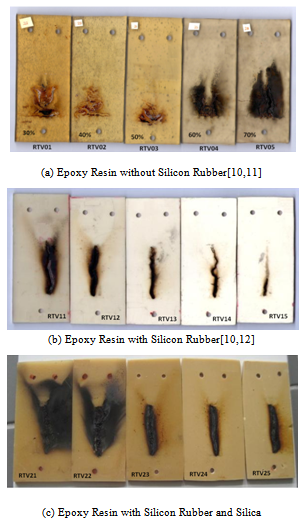 | Figure 21. Surface degradation and tracked zone |
Figure 21(b) shows the variation of silicone rubber composition influenced of the surface tracking. Surface condition of the sample with silicone rubber composition RTV11 seems severer damage than RTV14. This happens because silicone rubber of 40% will improve the surface properties of materials, so that the leakage current is more difficult to occur[15]. Measurements were taken with the same duration of time for each sample is 800 seconds (see Fig. 19).Figure 21(c) shows the surface degradation at variation of silicone rubber and silica sand composition. Surface condition of the sample with silicone rubber and silica sand composition RTV21 and RTV22 seems severer damage than other samples. All samples with silica sand show easily damage. This happens because silica sand reduces silicon rubber and properties of silica sand are hydrophilic and easily flammable.
5. Conclusions
The performance of epoxy resin compound with different compositions of silicon rubber and silica was investigated by analysing contact angle of hydrophobic, leakage current characteristics and surface degradation under the inclined-plane tracking test method. Experimental results showed that hydrophobic contact angle of samples, leakage current characteristics and surface degradation depend on the composition of silicon rubber. Based on the compositions investigated, it is found that samples with silicon rubber without silica sand offers the optimum surface tracking and erosion resistance. From this research we conclude that silica does not influenced on leakage current characteristics.
ACKNOWLEDGEMENTS
The first author would like to thank Mr. Daryadi and Mr. Prasetyohadi, B.Sc. who have set up and help this research. Also to Dr. T. Haryono as Chief of the High Voltage Laboratory has supported the implementation of this research.
References
| [1] | Berahim, H., K.T. Sirait, F. Soesianto, Tumiran, “A new performance of RTV Epoxy Resin Insulation material in tropical climate”, in Proceedings of 2003 IEEE the 7th International Conference on Properties and Applications of Dielectric Materials (ICPADM), pp 607, June 1-5, 2003. |
| [2] | J.A. Brydson, Plastic Materials. 4th edition, Butterworth Scientific, 1982. |
| [3] | Gorur,R.S., E.A. Cherney, J.T. Burharn. Outdoor Insulators. Ravi S. Gorur, Inc., Phoenix, Arizona 85044 USA, 1999. |
| [4] | Berahim H., “Methodology to assess the performance of silane epoxy resin insulating polymer as high voltage insulator materials in the tropical areas”. Ph. D Dissertation at Department of Electrical Engineering, Gadjah Mada University, Indonesia , 2005 |
| [5] | IEC Publication 1984, Testing Method for Evaluating Resistance of Tracking and Erosion of Electrical Insulating Materials used under severe Ambient Conditions, British Standards Institution, No. 587 |
| [6] | Kumagai, S., and Yoshimura, N. “Tracking and Erosion of HTV Silicon Rubber and Suppression Mechanism of ATH”, IEEE Transaction on Dielectric and Electrical Insulation 8(2): pp 203-211, 2001. |
| [7] | Naidu M.S., Kamaraju, V. High Voltage Engineering, 2nd Edition, Tata MC Graw Hill Publishing Company Limited, New Delhi. 1995. |
| [8] | Davis A., Sims D. Weathering of Polymers. 1st Edition. London: Applied Science Publisher Ltd. 1983. |
| [9] | Kind D, Kaerner H.C. High Voltage Insulation Technology. Braunschweig/Wiesbaden: Friedr Vieweg & Sohn.1985. |
| [10] | Abdul Syakur, Hamzah Berahim, Tumiran, Rochmadi. Leakage Current Measurement of Epoxy Resin Compound with Silicon Rubber. Proceedings of International Conference on Electrical Engineering and Informatics, Bandung, ITB, 2011. |
| [11] | Nurlailati, “ Analysis of surface degradation on epoxy resin due to tracking and erosion process” Thesis at Department of Electrical Engineering and Information Technology, Gadjah Mada University, Indonesia, 2010 |
| [12] | Ika N. Anggraini, “ The Influences of epoxy resin and silicon rubber composition to tracking and erosion Process” Thesis at Department of Electrical Engineering and Information Technology, Gadjah Mada University, Indonesia, 2010. |
| [13] | Abdul Syakur, Hamzah Berahim, Tumiran, Rochmadi. “Experimental investigation on electrical tracking of epoxy resin compound with silicon rubber”, Journal of High Voltage Engineering, Vol. 37, No. 11, November 30, 2011.pp. 2780 |
| [14] | Sarathi, R., S Chandrasekar, V Sabari Giri, C Venkataseshaiah and R Velmurugan, “Analysis of surface degradation of high density polyethylene (HDPE) insulation material due to tracking ” Bulletin of Material Science, Vol. 27, No. 3, June 2004 pp 251-262 |
| [15] | Chandrasekar, S., R. Sarathi, M.G. Danikas, “ Analysis of surface degradation of silicon rubber insulation due to tracking under different voltage profiles” Electrical Engineering(2007), 89:489-501. |


 Abstract
 Reference
 Full-Text PDF
 Full-Text HTML