Shahram Mohammadnejad 1, Mehdi Nasiri sarvi 1, Sobhan Roshani 2, Saeed Roshani 2
1Nanoptronics Research Center, School of Electrical Engineering, Iran University of Science and Technology, Tehran, Iran
2Islamic Azad University Kermanshah Branch, Kermanshah, Iran
Correspondence to: Sobhan Roshani , Islamic Azad University Kermanshah Branch, Kermanshah, Iran.
| Email: |  |
Copyright © 2012 Scientific & Academic Publishing. All Rights Reserved.
Abstract
The fixed pattern noise (FPN) is an important parameter in imaging devices such as CCD or CMOS sensors that becomes more important when we consider about precision. There is no simple technique to remove FPN without any inconvenience. An algorithm is proposed, which can reduce both, gain and offset FPN noise. At first, the gain FPN of all pixels will be unified. Then, the same procedure applies to the offset FPN. For a particular application in a star tracker, one can exploit stars image and its dark background or satellite motion to calibrate the camera during a mission. The efficiency of the proposed algorithm has been proved by simulation results. This technique also can be used in any camera or infrared devices that use a focal arrays system to observe the scenes.
Keywords:
CCD, CMOS, Fixed Pattern Noise, Satellite, Sensors, Star Tracker
Cite this paper:
Shahram Mohammadnejad , Mehdi Nasiri sarvi , Sobhan Roshani , Saeed Roshani , "A Novel Fixed Pattern Noise Reduction Technique in Image Sensors for Satellite Applications", Electrical and Electronic Engineering, Vol. 2 No. 5, 2012, pp. 271-276. doi: 10.5923/j.eee.20120205.05.
1. Introduction
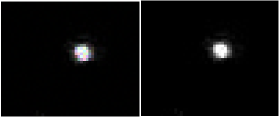
After launching the first satellite (Sputnik 1), thousands of them have been launched into orbit around the earth. The commonly used altitude classifications are low earth orbit (LEO), medium earth orbit (MEO) and high earth orbit (HEO). Low earth orbit is below 2000 km. satellite orbits depend on properties and objectives of sensors, they carry. For instance, most of the remote sensing satellites are placed in near-polar orbits. Recently high attitude accuracy has become more important. Attitude determination process determines the orientation of satellite with respect to a reference frame. Most Satellites use a star tracker to determine their attitude. Star tracker is an electronic camera that is connected to a processor[1,2]. They are classified based on different imager technologies such as active pixel sensor (APS), charge coupled device (CCD) or charge injection device (CID). Most commercial star trackers use CCD chips, because the CCD chips are low noise and are easily available. In the recent century, the use of LEO satellites has increased with the huge development of space technology. Commercial star trackers usually have mass of 3kg, accuracy of 10" (pitch/yaw) and 40" (roll), update rate of 40Hz and power consumption of 10W. Power consumption and radiation effects and mass can be reduced with using APS systems.Evolution of CMOS sensors, also called APS, represent a new era in the idea of star trackers. APS based system provides advantages, such as high radiation tolerance, random access capability, advanced capacity of integration in a system and standard CMOS clocking voltage. Although these devices are not as developed as CCDs[3]. These mentioned sensors suffer from variety of noises and disadvantages. Fixed pattern noise is one of these disadvantages. FPN refers to, pixel to pixel variation[4] -[7]. It is mainly due to dark current differences and it is fixed for a specific sensor, but change from sensor to sensor. FPN includes gain and offset component[8] -[12] that is random in CCD image sensors. CMOS sensors due to their readout circuit suffer from column FPN that appears as strip bands in the image[13]. The FPN in CCD and CMOS is shown in figure1. There are some methods for reducing FPN, such as correlated double sampling and flat fielding techniques[14]. These methods have many problems, for example FPN noise changes with temperature and time. Since those methods that reduce the FPN with permanent data, after some time periods or with temperature variation, may not work correctly.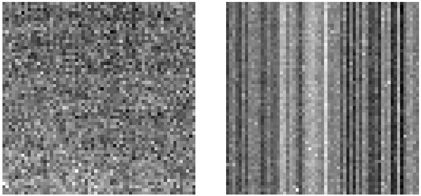 | Figure 1. FPN noise for CCD (left) and CMOS (right) noise |
A star tracker uses camera in order to determine of satellite attitude, therefore such method cannot be used because they forced to interrupt the camera imaging for calibration and many of them need laser and laboratorial devices. So we need to reduce the FPN without interruption and also need such process that can be upgraded during the time. In this paper a method is proposed, that reduces both, the gain and offset FPN in CCD sensors. This technique also can be used in any focal array imaging devices that follow linearity response model such as infrared focal arrays. These sensors need a black body to reduce nonlinearity or offset FPN which is expensive and need specific mechanical hardware and interruption of camera. Thus nowadays those techniques that based on post processing have been become more important [15].
2. FPN and Sensor Model
Fixed pattern noise includes gain and offset values. In CCD sensors because of unique amplifier for all pixels we have random FPN. However, in CMOS due to its perpendicular readout system, FPN appears in vertical line as seen in Fig.1. Common linear model for each pixel is used. For specific pixel, the output is come in below: | (1) |
where, “y” is the output signal of CCD for this pixel, “a” gain FPN, “b” offset FPN and “x” is input illumination that this pixel has been received. For ideal pixel without FPN noise, the value of “b” is zero and “a” must be equal to one. Only the magnitude of “y” is calculable and the other parameters (“a”, ”b”, ”x”) are unknown. If the complete arrays detector needs to be modeled, there are M×N pixels. Each pixel treats as a line, which has a different gain and offset value. Each pixel has its own model that produces nonuniformity in the detector and each of them has a unique output versus its illumination. After applying proposed algorithm that will be described at incoming topics, the whole pixels treat as a unique line. The output also can be written as following equation | (2) |
In this equation yi (m,n) represents the output of the pixel located in the m’th row and n’th column at i’th frame. In some methods, the value of a (m,n) considered to be unite, or b (m,n) considered to be zero, then FPN will be corrected. But we keep gain and offset values and then correct both of them.
3. Algorithm Description
3.1. Basic and Conditions
This algorithm is based on three images that are taken in a quick interval. These images can be provided, as satellite moves and takes images for procedure of star tracking. Hence, there are relations between pixels information. We can exploit these features and alter parameters of output pixels and improve these images. The second image is shifted version of first image and third image is shifted version of second or first image. As much as more pictures are taken, more information can be obtained, but these three images are sufficient to provide the information for the proposed algorithm. The detector that we considered is like figure2. The detector is under illumination. Yellow arrows show input illumination and blue arrows represent the output signal of the detector.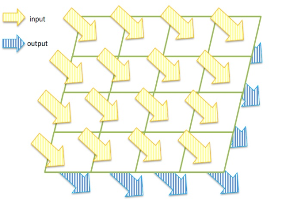 | Figure 2. Detector arrays exposure |
3.2. Gain Unification in Adjacent Pixels
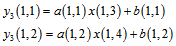
Suppose that a 4×4 elements linear arrays CCD is considered, hence, for the first column of the detector that is displayed in figure2, we can write: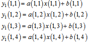 | (3) |
where value of “y” represents the output signal of the detector. As we said, only this value has been collected and the others are still unknown. In the next frame, we have: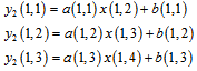 | (4) |
As it is seen there is a relation between these equations and the first frame equations. In these frames, we suppose that the illumination of the captured scene is constant. Fig 3 displays shifted detector for one pixel shifting that make second frame equations. Second pixel shifting is performed to allow us having fallowing equations.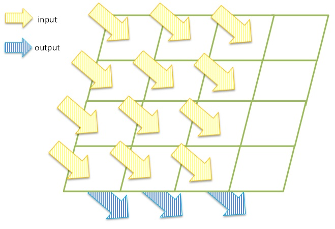 | Figure 3. Detector arrays exposure with one pixel shifting (second frame) |
 | (5) |
The condition in (4) is like (3), only the difference is one pixel shifting in arrays. Figure3 shows this movement. In (5), there is two times shifting instead of one time shifting that explained. In second frame, information of the last equation and in third frame, information of two first equations will be lost. This information distortion causes that a (1,4) element could not be unified simply. But this problem will be solved at next sections. The gain unification can be performed by applying these equations.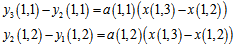 | (6) |
By dividing these two equations we have: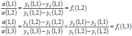 | (7) |
In (7),  obtained in same way as
 .
.  is called unification factor of pixel 2, with first pixel in first row. Because of information distortion that discussed before,
  cannot be calculated yet.After applying
  and
and  to first frame equations, it is seen that the gain of all pixels, except last pixel can be unified.
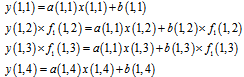 | (8) |
3.3. Last Column Unification Factor Determination
Since we have not shift information about last column pixel, we have to estimate the last unification factor with extra relations.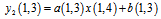 | (9) |
Therefor x (1,4) can be written as: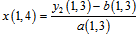 | (10) |
Applying (10) in  we have:
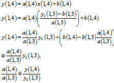 | (11) |
In (11) value of y(4,1) is approximated, because the value of 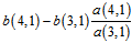 is negligible. Therefore the value of
  could be estimated as:
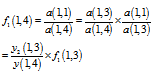 | (12) |
The gain unification can be rewritten as: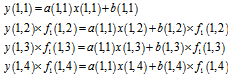 | (13) |
Hence, so far, the gain FPN has been unified. Then offset FPN must be unified. The final equation for gain correction can be written as following: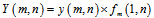 | (14) |
where  is corrected output and
 can be obtained as:
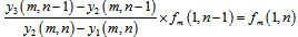 | (15) |
3.4. Offset Unification in Adjacent Pixels
These outputs have been obtained: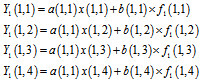 | (16) |
where  , second and third frame equations change to these:
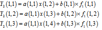 | (17) |
and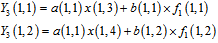 | (18) |
Offset unification constant can be defined for bias values, like gain unification factor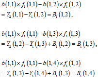 | (19) |
After adding B values to main equation we have unified detector that is completely treats linear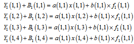 | (20) |
where B (1,1) = 0.This equation can be extended to all pixels with following equation. | (21) |
The final correction formula can be calculated as: | (22) |
One column could be unified until now. 90 degrees rotation of the camera can help us to find the relation between columns. It means that the camera rotates 90 degrees and then the proposed algorithm applied to image again, one more time. After unifying the first column, the remaining columns and all of pixels can be unified. Procedure of proposed algorithm is explained in figure4. The algorithm initially unifies the first column. Then, the camera rotates and this process will be continued again until all of pixels will be unified. The ideal offset could be easily obtained by comparing offset values. For example, in (19) every pixel bias values compared with first pixel. It csould be extended to find out the best bias value. In order to find the best gain value, the same procedure is conducted. Hence, the unification will be based on the best gain and bias values rather than first pixel.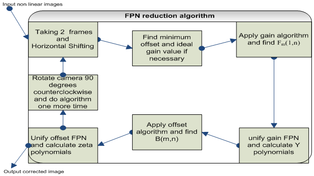 | Figure 4. Description of proposed algorithm |
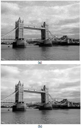
 | Figure 5. (a) image with FPN noise (b) after applying the proposed algorithm |
4. Simulation Results
 | Figure 6. Original sample image |
 | Figure 7. (a) After adding FPN noise on image (b) The image after applying algorithm |
For testing the proposed algorithm, first we simulate a detector that follows the linear model which described earlier. The proposed algorithm is applied to typical stars photo, which may use for attitude determination in a satellite. This photo is taken by 2048x2048x12 bit high resolution CCD sensor camera. Comparing two photos in figure5, after applying the algorithm, FPN noise is significantly removed. The proposed algorithm can reduce FPN noise, which added to simulated image. According to proposed algorithm it can be seen that, it is more efficient in uniform scenes. It means, when we have low contrast, it seems better. FPN noise in CCD sensors is random, therefore FPN noise added to the raw image randomly. After adding noise to image, the proposed algorithm applied to it. Figure6 shows an original image that is taken by 12 Megapixels Panasonic Lumix DMC-GF1 camera with the 20mm f/1.7 pancake lens. The original image has no FPN noise. After adding FPN noise to image, the proposed algorithm applied to it. This procedure is shown in figure7. In practice the algorithm needs three integers or noninteger shifted frame, but in our simulation the camera shifting process was simulated. It means when the FPN noise is modeled to image, it is possible to shift the image which is similar to practical shifting. Suppose that we want to shift the first column to the second column, each parameter of gain or offset noise in this column apply to new pixels that are shifted. It is possible to simply, changes the algorithm in noninteger shifting process with two coefficients of row and column.
5. Conclusions
In the star tracker the light distribution of stars is very important and if it is defected by noises, such as FPN and nonlinearity, the exact center of stars could be dislocated. In this paper, an algorithm is proposed which is based on pixel shifting. The algorithm could be extended easily to non-integer pixel shifting mode. The proposed algorithm has been described with an example of 4×4 detector for simplification. It is seen that this procedure reduced nonlinearity of FPN of a typical stars image and improved image quality. All pixels have been unified with gain factors and offset constants. Also it is possible to write an algorithm to find the best pixel in the detector which has ideal gain factor and minimum offset value and then, unify all pixels with its characteristics. However this algorithm cannot completely fix both, gain and offset, but it unifies them in a simple way.
References
| [1] | C. Liebe, L. Alkalai, G. Domingo, B. Hancock, D. Hunter, J. Mellstrom, I. Ruiz, C. Sepulveda, and B. Pain, "Micro APS based star tracker," 2002 |
| [2] | C. C. Liebe, "Accuracy performance of star trackers-a tutorial," Aerospace and Electronic Systems, IEEE Transactions on, vol. 38, pp. 587-599, 2002. |
| [3] | L. Rousseau, "Star recognition algorithm for APS star tracker: oriented triangles," IEEE Aerospace and Electronic Systems Magazine, vol. 20, pp. 27-31, 2005. |
| [4] | J. M. Mooney, "Effect of spatial noise on the minimum resolvable temperature of a staring sensor," Applied optics, vol. 30, pp. 3324-3332, 1991. |
| [5] | J. M. Mooney, F. D. Shepherd, W. S. Ewing, J. E. Murguia, and J. Silverman, "Responsivity nonuniformity limited performance of infrared staring cameras," Optical Engineering, vol. 28, pp. 1151-1161, 1989. |
| [6] | A. Blanksby and M. J. Loinaz, “Performance analysis of a color CMOS photogate image sensor,” IEEE Trans. Electron Devices, vol. 47, pp. 55–64, Jan. 2000. |
| [7] | A. El Gamal, B. Fowler, H. Min, and X. Liu, “Modeling and estimation of FPN components in CMOS image sensors,” in Proc. SPIE Electronic, pp. 168-177, 1998 |
| [8] | Z. Ignjatovic, D. Maricic, and M. F. Bocko, "Low Power, High Dynamic Range CMOS Image Sensor Employing Pixel-Level Oversampling Analog-to-Digital Conversion," IEEE SENSORS JOURNAL, vol. 12, p. 737, 2011. |
| [9] | E. N. Linzer and L. D. Kohn, "Fixed pattern noise correction with compressed gain and offset," Google Patents, 2011. |
| [10] | A. E. Mudau, C. J. Willers, D. Griffith, and F. P. J. le Roux, "Non-uniformity correction and bad pixel replacement on LWIR and MWIR images," pp. 1-5, 2011. |
| [11] | P. J. L. Van Beek, "CAMERA NOISE REDUCTION FOR MACHINE VISION SYSTEMS," US Patent 20,120,075,505, 2011. |
| [12] | C. San Martin, R. Carrillo, P. Meza, H. Mendez-Vazquez, Y. Plasencia, E. GarcÃa-Reyes, and G. Hermosilla, "Recent Advances on Face Recognition Using Thermal Infrared Images," InTech, 2011. |
| [13] | L. SukHwan, A. El Gamal, "Gain fixed pattern noise correction via optical flow" IEEE Transaction on Circuit and Systems I, , vol. 51, pp.779-786, 2004. |
| [14] | V. Schneider, fixed-pattern correction of HDR image sensors, "Research in Microelectronics and Electronics," pp. 99-102, 2005. |
| [15] | U. Sakoglu, R. C. Hardie, M. M. Hayat, B. M. Ratliff, and J. S. Tyo, "An algebraic restoration method for estimating fixed-pattern noise in infrared imagery from a video sequence," Applications of Digital Image Processing XXVII, vol. 5558, pp. 69–79. |
 Abstract
 Reference
 Full-Text PDF
 Full-Text HTML