Funso K. Ariyo , Olusegun Emmanuel , Femi Aworo , M. O. Omoigui
Department of Electronic and Electrical Engineering, Obafemi Awolowo University, Ile-Ife, Nigeria
Correspondence to: Funso K. Ariyo , Department of Electronic and Electrical Engineering, Obafemi Awolowo University, Ile-Ife, Nigeria.
| Email: |  |
Copyright © 2012 Scientific & Academic Publishing. All Rights Reserved.
Abstract
In this paper an attempt has been made to propose a new technique for selection of optimum site of a power system stabilizer (PSS) to mitigate the small-signal stability problem in a multimachine power system. Study reveals that the PSS displaces the swing mode from its critical position to a more desirable position changing the response of the excitation system. Based on the change of the exciter transfer function with respect to the PSS transfer function, an Optimum PSS Location Index (OPLI) has been introduced and used to identify the best location of the PSS in a multimachine system. The analysis of the effect of load on eigenvalues confirms that the prediction of best location of PSS by OPLI method is more effective in enhancing the small-signal stability of the system.
Keywords:
Critical Swing Mode, Optimum PSS Location Index, Sensitivity of PSS Effect, Small Signal Stability
Cite this paper:
Funso K. Ariyo , Olusegun Emmanuel , Femi Aworo , M. O. Omoigui , "Selection of Optimum Location of Power System Stabilizer in a Multimachine Power System", Electrical and Electronic Engineering, Vol. 2 No. 5, 2012, pp. 258-265. doi: 10.5923/j.eee.20120205.03.
1. Introduction
The enhancement of damping of electromechanical oscillations in multimachine power systems by the application of a Power System Stabilizer (PSS) has been a subject of great attention in the past three decades[1] –[5]. It is much more significant today when many large and complex power systems frequently operate close to their stability limits. Though, there is common perception that the application of PSS is almost a mandatory requirement on all generators in modern power network but in developing countries, where power networks are mostly longitudinal in nature, constrained economy limits the use of high price PSS with each and every generator. In view of the potentially high cost of using a PSS and to assess its effectiveness in damping poorly damped swing modes to achieve better stability, identification of the optimum site of PSS is still an important task to the researcher. The issue of suitably choosing the location of a PSS in a multimachine system has been first investigated by[6].A coherency-based identification method was proposed by[7], where a quadratic performance index determines the most suitable location of the PSS for the coherent group. A new coordinated synthesis method was proposed by[8], by combining eigenvalue sensitivity analysis and linear programming to select the machine to which the PSS can be effectively applied. The concept of the participation-factor was used by[9], where the machine having the greatest participation factor for the most poorly damped swing mode is chosen as the optimum site for the stabilizer location. The concept of the participation-factor is extended further by[10], by introducing a new coupling-factor. In order to investigate the effects of control input on the modes, in[11], the authors have taken the control matrix B into consideration and have used a certain type of PSS which can effectively determine the optimum location. Recently a powerful optimization technique, Genetic Algorithm (GA), was used by[12] to select the optimum location and design of a robust multimachine PSS. In the present work, a simple and straight-forward approach is proposed using the change of response of the excitation system with respect to the response of PSS in a certain swing mode. A new index, called Optimum PSS Location Index (OPLI) has been introduced. As the PSS acts through the excitation system, it was found that the magnitude of OPLI is large for that machine where the effect of PSS on the exciter is large. The advantage of this method is that, it is possible to identify the best installing location of PSS from the knowledge of the oscillation mode of interest and the transfer function of the excitation system of the respective machine only. In the following section, a full-order multimachine model including a first-order power system stabilizer with all network dynamics has been considered. An example of a 3-machine, 9-bus system has been adopted and the PSS is applied sequentially to each machine and the improvement in damping of the critical mode of the system has been observed. Next the optimum location of PSS is searched through the proposed new method of Optimum PSS Location Index (OPLI) and it appears that the new method gives a similar prediction of PSS location as obtained using the existing SPE method. Finally the effect of load variation on eigenvalues has been investigated and it was observed that the PSS improves small-signal stability and gives maximum improvement when installed at the optimum location. The new OPLI method seems to be more superior and acceptable than the existing SPE method, as it considers the full order multimachine linearized model including all type of network buses, where as the SPE method has used the reduced-order multimachine linearized model considering generator buses only eliminating other network buses.
1.1. Criterion for Identification of Swing Modes
The swing mode of a power system can be identified by the criterion proposed by[13]. The authors have used a swing mode identification index termed as swing-loop participation ratio. The swing modes are closely related to the electromechanical swing-loops associated with the relevant state variables like rotor angle (Δδ) and machine speed (Δω). The swing-loop participation ratio (Ph) has been defined as: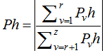 | (1) |
Where  is the participation factor of the
  state variable for the
  mode. ‘z’ represents the total number of state variables and ‘r’ represents the number of relevant states belongings to the state variable set[Δδ, Δω].The proposed criterion states that gnerally the oscillation frequencies of the swing modes are in the range of 0.2 - 2.5 Hz and their swing-loop participation ratio
  .
.
1.2. Control Effect of PSS
The PSS acts through the exciter and provides control effect to the power system under consideration. If the exciter is kept off, the PSS will have no effect on the system. The control effect of PSS on the system (by the PSS output state  and the system mode
  ) can be measured by the following coefficient:
 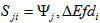 | (2) |
For i = 1, 2, ..., m (number of machines). Here 
 is the left eigen vector entry of
  mode (
 ) corresponding to the state variable
  .
.
1.3. Concept of Best PSS Location Selection Indicator
During application of PSS to a multi-machine power system to achieve the largest improvement in damping, the primary task is to identify the best location of PSS. In order to take into consideration the effect of both the PSS input and the PSS control in selecting the PSS location, Sensitivity of PSS Effect (SPE) for the  machine was considered
 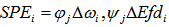 | (3) |
For i = 1, 2,…….., m (number of machines), where  is the right-eigenvector entry and
  is the left-eigenvector entry of
  mode corresponding to the state
  and
and  of the
  machine. SPE measures both the activity of PSS input (
 ) participating in a certain oscillatory mode as well as the control effect of PSS, on this mode. The larger the magnitude of the SPE, the better the overall performance of the PSS in a multi machine power system and there may be several swing modes which are of interest and for each mode a set of {
 where i =1, 2,……, m} can be calculated by (9). The SPE with largest magnitude of any
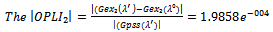
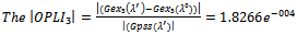
  machine identifies the best location of PSS. The newly proposed concept of Optimum PSS Location Index (OPLI) is based on the change of exciter transfer function with respect to the PSS transfer function in a certain swing mode. The PSS on a machine is a closed-loop controller which considers usually the machine speed or power as its input and introduces a damping so that the system moves from a less stable region to a more stable region. As the PSS acts through the excitation system, the effect of displacement of swing modes due to installation of PSS will change the response of the excitation system. The response of the excitation system at a swing mode
  can be obtained by replacing
  for‘s’ in its transfer function
  The change of response of the excitation system with respect to the PSS response for a swing mode
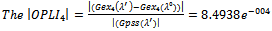
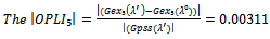
  is determined by the proposed index OPLI which is defined by:
 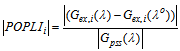 | (4) |
For i =1, 2, …, m (no. of machines). Here  and
and  are the critical swing modes before and after the installation of PSS respectively. The magnitude of OPLI measures the effect of PSS on the exciter response in a swing mode of
  interest. The larger the value of the OPLI the larger is the control effect of PSS on the exciter and the better is the overall performance of PSS in the power system.
2. Simulation and Application
2.1. Computation of Eigenvalues and Swing Modes Prior to Application of PSS
The modal analysis approach using eigenvalues and swing mode computation techniques are commonly used tools[14] –[16] for small signal stability problem. The popular Nigerian Power system 7-Machine, 26-bus system has been considered in this paper as a test case and is shown in Figure 1.0. Uniform damping has been assumed for all the seven machines. The computed eigenvalues or the electromechanical modes of the system without PSS are listed in Table1. It is clear from the 4th column of Table 1 that the damping ratio (z) of the electromechanical mode #1 ( ) is the smallest and therefore, the behavior of this mode is important to study the small-signal stability of the system. This mode has been referred to as the critical mode. The mode frequency and the participation factor analysis suggest that the nature of the critical mode without PSS is a local mode and is strongly associated with the machine #2 and the system states (Δδ, Δω). The swing-loop participation ratio for each electromechanical mode has been shown in column 5 of Table 1.0, which interprets that the mode #1 and #2 are the swing modes and among which mode #1 is the most critical swing mode. Hence the power system stabilizer should be placed at an optimum location, so that it can yield maximum damping to the electromechanical oscillation of the critical swing mode (#1)
2.2. Application of Power System Stabilizer
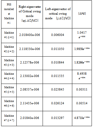
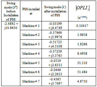
In this section the PSS has been applied to the proposed system (Figure 1.0). Though the damping of the generators of the test system is reasonably good, still small signal stability problems have been observed in the test system and hence attempts have been made to install the PSS in an optimum location in order to exhibit the improvement of critical swing mode (#1) using the PSS. The swing modes get affected with the installation of the PSS at any of the three machines. However, the response of the critical swing mode being of prime concern, it has been observed that the improvement in the critical swing mode is of highest degree as shown in Table 2.0 if the PSS is installed at machine #2. Both the existing SPE and the newly proposed OPLI are calculated for individual machines using (9) and (10).The corresponding magnitudes of SPE and OPLI are listed in Tables 3.0 and 4.0 respectively. Considering the nature of the critical swing mode and the magnitudes of the two indicators SPE and OPLI, it is possible to conclude that the machine #2 should be the best location of PSS. 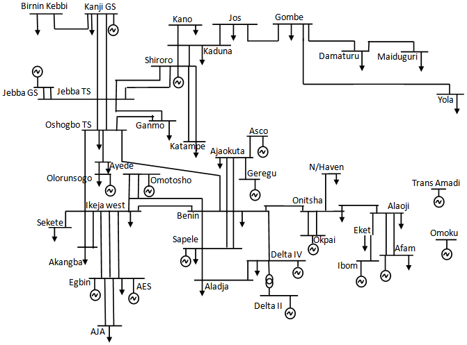 | Figure 1. Single Line Diagram of the 330 kV Nigerian Power System |
| Table 1. Critical swing mode and damping ratio before and after installation of PSS |
| | | Critical swing mode

| Damping Ratio

| | Before installation of PSS | -0.03015 + j4.50442 | 0.2233 | | PSS installed at machine #1 | -0.03199 + j4.47497 | 0.2262 | | PSS installed at machine #2 | -0.37969 + j5.99766 | 0.3120 | | PSS installed at machine #3 | -0.51723 + j4.31080 | 0.2224 | | PSS installed at machine #4 | -0.37239 + j3.37658 | 0.3456 | | PSS installed at machine #5 | -0.0519 + j2.63115 | 0.3480 | | PSS installed at machine #6 | 0.04463 + j2.26131 | 0.4260 | | PSS installed at machine #7 | -0.43659 + j3.70975 | 0.4458 |
|
|
Table 2. Magnitude of SPE when PSS installed at individual machine
 |
| |
|
Table 3. Magnitude of OPLI when PSS installed at individual machine
 |
| |
|
| Table 4. Effect of load on critical swing mode |
| | # | Real load (Pι)(pu) | Reactive load (Qι)(pu) | Critical swing mode () before installation of PSS | Critical swing mode for optimum () location of PSS (machine #2) | | 1 | 1.25 (Base load) | 0.5 | -2.4892 + j10.8650 | -3.5586 + j10.8354 | | 2 | 1.5 | 0. 5 | -2.4745 + j10.9692 | -3.3502 + j10.9232 | | 3 | 2.5 | 0.5 | -2.4031 + j11.3400 | -3.0547 + j11.3793 | | 4 | 3.5 | 0.5 | -2.3074 + j11.6323 | -2.7576 + j11.6532 | | 5 | 1.25 | 1.0 | -2.4468 + j10.6290 | -3.4368 + j10.4549 | | 6 | 1.25 | 1.5 | -2.4210 + j10.8862 | -3.2897 + j10.8578 |
|
|
3. Characteristics of SPE and OPLI with PSS Gain
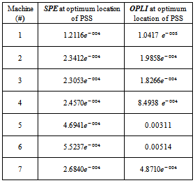
The characteristics of OPLI with variation of PSS gain has been investigated in this section and compared with the characteristics of SPE. With PSS installed at machine #1 and #2, …,#7. both the SPE and OPLI characteristics show increment with increase in PSS gain. For machine #3 both of these sensitivity parameters exhibit decrement with increasing PSS gain. It has been further observed that the slope of the profile of SPE as well as OPLI, both are high for optimum location of the PSS. Thus it appears that the proposed index OPLI bears similar characteristics as SPE and can be effectively used instead of SPE to predict the optimum location of PSS.When the PSS is installed at the optimum location that is machine #2, the obtained eigenvalues are represented in Table 5.0 This illustrates that with an increase of load (real or reactive) the system stability decreases before installation of PSS and improves significantly when PSS is installed. It has also been confirmed in this study that the relative improvement of stability at the selected optimum location of PSS is more in comparison to the other two locations (machine #1 and #3). The effect of load on SPE and OPLI have also been investigated and it was observed that even with increasing load, both the sensitivity parameters are reasonably accurate as shown in Table 5.0 The functionality of the algorithm and program designed Dynamic stability analysis using the OPLI and SPE method for the optimum location of the PSS in the Nigerian network. It is independent on the combination of the number of programs written and designed to perform specific functions in the entire analysis. These programs include:Ⅰ Matrix program: This helps to generate the matrix used for the PSS.Ⅱ The results obtained below suggest that SPE and OPLI gave results with similar trend. Hence, OPLI method can be seen as shown below including complex algorithms. Ⅲ The graph of OPLI against gain is also shown below. The effect of load increase on SPE and OPLI has also been shown.Table 5. Effect of Load on PSS Location Indicators
 |
| |
|
4. Algorithms for the Calculation of OPLI
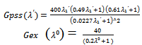
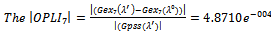
1. Derive the transfer function of the excitation system Gex(s)2. Calculate the  here
here  (= -0.030155599 + j 4.50442475) is the critical swing mode #1, before application of PSS. 3. Install the PSS at any machine with parameters, assumed
  = 20, τ₁ = 0.49 and τ₃ = 0.61. Here,
 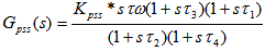 4. Compute the system matrix system Asys and eigenvalues after application of PSS.5. Note the critical swing mode
  to obtain
  and
and  .6. Calculate the OPLI applying equation given. 7. Repeat steps 1-6 for each machine.
4.1. Transfer Function of the IEEE-Type 1 Exciter
The state space form of the exciter is represented as: 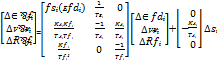 | (5) |
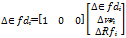 | (6) |
where, Sᴇ (ᴇfd) = 0.0039exp (1.55 ᴇfd), for i = 1, 2, 3, … , m (number of machines).Equations (5) and (6) together give the transfer function of the exciter for the i-th machine, 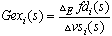 , The exciter transfer function for machines #1, #2 and #3 are;
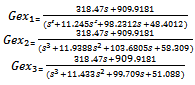
4.2. Application of PSS
4.2.1. Machine #1
The critical swing mode, 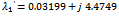
 and
and
4.2.2. Machine #2
The critical swing mode, 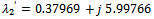
4.2.3. Machine #3
The critical swing mode, 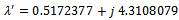
4.2.4. Machine #4
The critical swing mode, 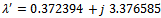
4.2.5. Machine #5
The critical swing mode, 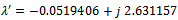
4.2.6. Machine #6
The critical swing mode, 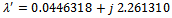

4.2.7. Machine #7
The critical swing mode, 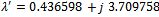
 The OPLI versus PSS gain for Machines #1 - #7 are shown in figures 2.0 – 8.0 respectively. Also, figure 9.0 shows the PSS structural mode in the Appendix.
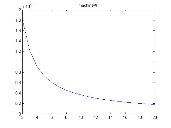 | Figure 2. OPLI vs PSS gain when installed at machine #1 |
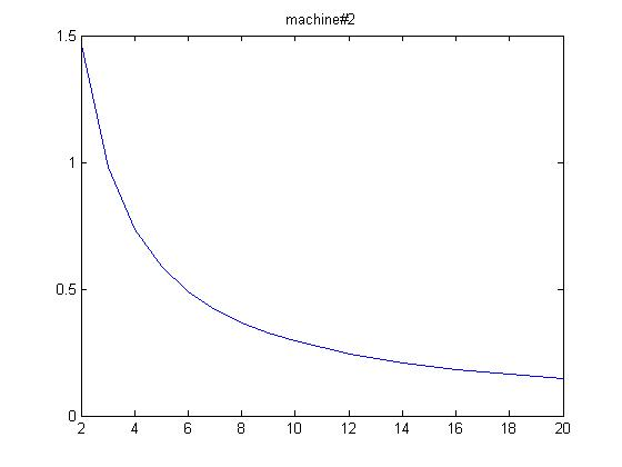 | Figure 3. OPLI vs PSS gain when installed at machine #2 |
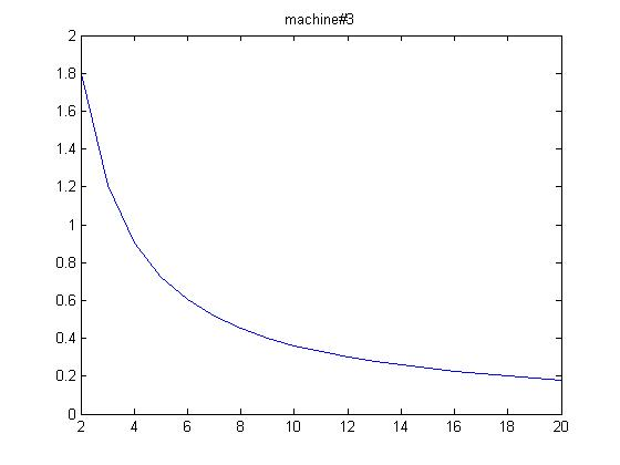 | Figure 4. OPLI vs PSS gain when installed at machine #3 |
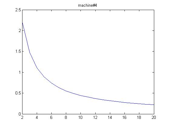 | Figure 5. OPLI vs PSS gain when installed at machine #4 |
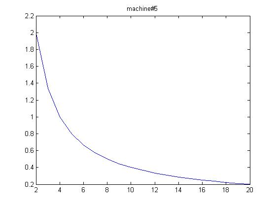 | Figure 6. OPLI vs PSS gain when installed at machine #5 |
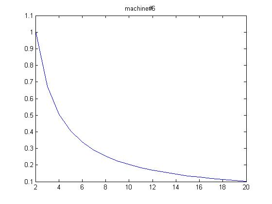 | Figure 7. OPLI vs PSS gain at machine #6 |
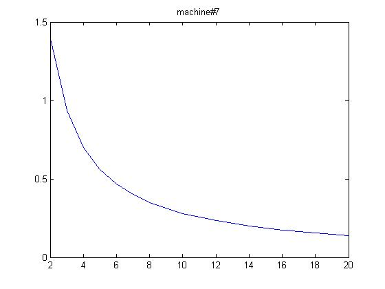 | Figure 8. OPLI vs PSS gain when installed at machine #7 |
5. Conclusions
This paper presents a new approach to identify the optimum site for installation of power system stabilizer in a multi-machine system. The procedure was based on the change of the exciter transfer function with respect to the PSS transfer function for a critical swing mode of interest. The proposed OPLI method and existing SPE method were tested for a 7-machine, 32-bus system and the results obtained revealed that both methods provide identical prediction in selecting optimum location of PSS. The present study also reveals that the proposed index is suitable for application of PSS even during heavy loading condition and till the system approaches its critical operating limit. The proposed approach appears to be more acceptable and accurate than the existing method as it considers the multi-machine full-order linearized model including all network bus dynamics.The development of a software for the analysis of the dynamic stability of power systems has been quite challenging. It has also been observed that when three PSSs are installed at machines 4,5 and 6, they will damp out all the local and inter-area oscillation modes. Hence, the cost is reduced while achieving the desired system reliability. During the analysis, several assumptions were made in order to reduce the complexity of the analysis and coding of the algorithms.
Appendix
Data for the test systemB.1 Machine parameters (p.u) B.2 Exciter (IEEE Type-1) Parameters
 Transmission line parameters (p.u)re = 0.02 ; xe = 0.4NOTE: If an eigenvalue is given by s = α ± jβ , then damping ratio =
  where α ≤ 0
 | Figure 9. PSS structural mode |
References
| [1] | Larsen EV, Swann DA (1981). Applying power system stabilizer, part 1: General concept, part II: Performance objective and Tuning concept, part III: Practical considerations. IEEE Trans. Power Apparatus and Systems 100(12): 3017-3046. |
| [2] | Abe S, Doi A. (1983). A new power system stabilizer synthesis in multi-machine power systems, IEEE Trans. Power Apparatus and Systems 102(12): 3910-3918. |
| [3] | Hsu Y, Liu C, Lin CJ, Hung CT (1988). Application of power system stabilizers and static var compensators on a longitudinal power system. IEEE Trans. on Power Systems 3(4): 1464-1470. |
| [4] | Kundur P, Klein M, Rogers GJ, Zywno MS (1989). Application of power system stabilizers for enhancement of overall system stability. IEEE Trans. on Power Systems 4(2): 614-626. |
| [5] | Zhou EZ, Malik OP, Hope GS (1992).Design of stabilizer for a multimachine power system based on the sensitivity of PSS effect. IEEE Trans. On Energy Convers. 7(3): 606-613. |
| [6] | deMello FP, Nolan PJ , Laskowski TF, Undrill JM (1980). Coordinated application of stabilizer in multimachine power system. IEEE Trans. on Power Apparatus and Systems 99(3): 892-901. |
| [7] | Hiyama T (1983). Coherency-based identification of optimum site for stabilizer applications, Proc. of IEEE 130C (2): 71-74. |
| [8] | Doi A, Abe S (1984). Coordinated synthesis of power system stabilizers in multi-machine power systems. IEEE Trans. on Power Apparatus and Systems 103(6): 1473-1479. |
| [9] | Chen CL, and Hu YY (1988). An efficient algorithm for design of decentralized output feedback power system stabilizer, IEEE Trans. on Power Systems 3(3): 999-1004. |
| [10] | Ostojc DR (1988). Identification of optimum site for power system stabilizer applications, Proc. of IEE 135C(5): 416- 419. |
| [11] | Chiang JL, and Thorp JS (1990). Identification of optimum site for power system stabilizer applications. IEEE Trans. on Power Systems 5(4):1302-1308. |
| [12] | Sebaa K, and Boudour M (2006). Optimal location and tuning of robust power system stabilizers using genetic algorithm. IEEE IEC on Industrial Electronics pp. 501-506. |
| [13] | Zhou EZ, Malik OP, Hope GS (1991). A reduced-order iterative method for swing mode computation. IEEE Trans. on Power Systems 6(3): 224-1230. |
| [14] | Okubo S, Suzuki H, Uemura K (1978). Modal analysis for power system dynamic stability. IEEE Trans. on Power Apparatus and Systems 97(4): 1313-1318. |
| [15] | Obata Y, Takeda S, Suzuki H (1981). An efficient eigenvalue estimation technique for multimachine power system dynamic stability analysis. IEEE Trans. on Power Apparatus and Systems 100(1): 259-263. |
| [16] | Perez-Arriaga IJ, Verghese GC, Schweppe FC (1982). Selective modal analysis with applications to electric power system, part-II, The dynamic stability problem. IEEE Trans. on Power Apparatus and Systems 101(9): 3126-3134. |
 Abstract
 Reference
 Full-Text PDF
 Full-Text HTML