Funso K. Ariyo , M. O. Omoigui
Department of Electronic and Electrical Engineering, Obafemi Awolowo University, Ile-Ife, Nigeria
Correspondence to: Funso K. Ariyo , Department of Electronic and Electrical Engineering, Obafemi Awolowo University, Ile-Ife, Nigeria.
| Email: |  |
Copyright © 2012 Scientific & Academic Publishing. All Rights Reserved.
Abstract
The study simulated the behaviour of power system stabilizer (PSS) on automatic voltage regulator (AVR) and excitation system. It also developed an algorithm to investigate the transient and dynamic stability of the power systems. This was with a view to providing information of damping rotor oscillations of synchronous generators. Three types of power systems were investigated: a single-machine-infinite-bus system with and without PSS, two generators connected to a load with various types of excitation controls and a multimachine power system typified by Nigerian 330-kV electrical network. Tabu-search technique was used to tune the PSS-parameters for a single machine connected to an infinite bus operating at three different loading conditions. The objective function allowed the selection of the stabilizer parameters to optimally place the closed-loop eigenvalues in the left-hand side of a vertical line in the complex s-plane. The effectiveness of this suggested technique was confirmed through eigenvalue analysis. Time-domain simulations were also carried out on two generators connected to a load using MATLAB/Simulink. Two types of PSS were used for these simulations: generic and multiband. The power systems were subjected to a balanced three-phase fault (most severe fault). The investigation was further extended to Nigerian 330-kV electrical network.
Keywords:
Power System Stabilizer, Automatic Voltage Regulator, Excitation System, Stability, Damping Rotor Oscillations, Tabu-Search Technique
1. Introduction
Any physical system that is designed or operated to perform a certain pre-assigned task in a steady-state mode should, in addition to performing these task functions in a satisfactory manner, have the ability to regain stability after sudden disturbances with an adequate margin of safety. When the physical system is large and complex such as a typical modern interconnected power system, investigation of stability requires analytical sophistication in terms of techniques employed and practical experience in interpreting the results properly.In the last three and a half decades and in particular after the famous blackout in U.S.A. in 1965, considerable research effort has gone into the stability investigation of power systems both off-line and on-line purposes[1]. At the design stage although, the planner takes some contingencies into consideration, in subsequent operation and augmentation of the network, new considerations may arise which were not foreseen by the planner. Hence, an entirely new pattern of system behavior can be expected under actual operating conditions. This is particularly true regarding the capability of the system to maintain synchronism or stability due to sudden unforeseen disturbances such as loss of a major transmission line, load or generation. Stability is a condition of equilibrium between opposing forces. The mechanism by which interconnectedsynchronous machines maintain synchronism with one another is through restoring forces, which act whenever there are forces tending to accelerate or decelerate one or more machines with respect to other machines. For any given situation, the stability of the system depends on whether or not the deviation in angular positions of the rotors results in sufficient restoring torques. When a synchronous machine loses synchronism or “falls out of step” with the rest of the system, its rotor runs at a higher or lower speed than that required to generate voltages at system frequency. The slip between rotating stator field and the rotor fields results in large fluctuations in the machine power output, current and voltage. This causes the protection system to isolate the unstable machine from the system.Loss of synchronism can occur between one machine and the rest of the system or between groups of machines. In the latter case, synchronism may be maintained within each group after its separation from the others[2].Supplementary excitation control of the low-frequency oscillations is well known as a Power System Stabilizer (PSS). Since the 1960’s, PSSs have been used to add damping to electromechanical oscillations. They act through the generator’s excitation system to generate a component of electrical torque, called damping torque, proportional to speed change. Since then, applying PSSs has attracted the attention of researchers. Extensive research has been conducted in such fields as effect of PSS on power system stability, PSS input signals and PSS tuning techniques[3]. Several approaches for designing a PSS for improving transient and dynamic stability of power system have been suggested in the literature[3-11].
2. The Need for Power System Stabilizer
The effect of AVR is to increase the synchronizing torque component and decrease the damping torque component. Hence, the basic function of a PSS is to add damping to the generator rotor oscillations by controlling its excitation using auxiliary stability signals. To provide damping, the stabilizer must produce a component of electrical torque in phase with the rotor speed deviations.With electric power systems, the change in electrical torque of a synchronous machine following a perturbation can be resolved into two components as shown in equation (1.1)[2]: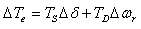 | (1.1) |
where  is the component of torque change in phase with the rotor angle perturbation
  and is referred to as the synchronizing torque component,
  is the synchronizing torque coefficient.
 is the component of the torque in phase with the speed deviation,
  and is referred to as the damping torque coefficient and
  is the damping torque coefficient.Therefore, the PSS produces just enough damping to compensate for the negative damping due to the AVR-action. As the PSS gain is increased further, the amount of damping increases. Fig 1.0 shows the block diagram of the excitation system including the AVR and PSS, neglecting the stabilizer output limits and exciter output limits. The PSS representation in fig. 1 consists of three blocks: a phase compensation block, a signal washout block and a gain block.Ⅰ. The phase compensation block provides the appropriate phase-lead characteristic to compensate for the phase-lag between the exciter input and the generator electrical (air-gap) torque.Fig. 1.0 shows two-first-order block, but in practice, three or more first-order blocks may be used to achieve the desired phase compensation. Normally, the frequency range is 0.1 to 0.2 Hz and the phase-lead network should provide compensation over the entire frequency range. The phase characteristic to be compensated changes with system conditions. Generally, some under-compensation is desirable so that the PSS, in addition to significantly increasing the damping torque, results in a slight increase of the synchronizing torque.Ⅱ. The washout block serves as a high-pass filter with the time constant
  high enough to allow signals associated with oscillation in
  (or
(or ) to pass unchanged. Without it, steady changes in speed would modify the terminal voltage. It allows the PSS to respond only to changes in speed.
  will range between 1 to 20 seconds. It should be long enough to pass stabilizing signals at the frequencies of interest unchanged, but not too long that it leads to undesirable generator voltage excursions during system-islanding conditions.Ⅲ. The Stabiliser gain
  determines the amount of damping introduced by the PSS. Ideally, the gain should be set at a value corresponding to maximum damping. In applying the PSS, the overall system stability must be enhanced.The complete state space model including PSS has the following form expressed in (2) (with
 .
.
3. Design of Power System Stabilizer
The stability and damping effect that could be achieved by introducing an additional signal into the AVR was investigated. Firstly, for a one-machine infinite bus system and secondly for a two-machine system. In both cases, the additional signal and its shaping constituted the power system stabilizer (PSS) which was concluded merely as a gain constant with or without time lag. In practice, the PSS could be complicated depending upon the signal employed and the system involved. One method of achieving such a model is the use of tabu search[12]. In reality, a large number of machines interact with each other through network voltages and power flows. The effect of the dynamics of other machines, therefore, must be taken into consideration whilst designing a particular PSS. This is known as coordinated tuning of PSS in a multi-machine system. 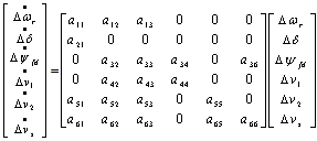 | (2) |
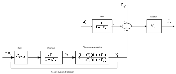 | Figure 1. Thyristor-excitation system with AVR and PSS[2] |
A. Tabu SearchTabu Search was originally proposed as an optimization tool by Glover in 1977[13]. Tabu search is an iterative improvement procedure in that it goes from some initial feasible trial solution to another by making moves. It makes several candidate moves and selects the move producing the best solution among all candidates’ moves for the current iteration. The set of admissible moves form a candidate list. The best candidate solution becomes the current solution.It is well known that machine parameters change with loading, making the dynamic behavior of the machine quite different at varying operating conditions. Consequently, a set of power system stabilizer (PSS) parameters which stabilize the system under a certain operating condition may no longer yield satisfactory results when there is a drastic change in the operating point. In this report, the power system, operating at various loading conditions was treated as a finite set of plants, and a PSS with parameters that can simultaneously improve the damping of this set of plants is determined off-line using a tabu search and an objective function based on the system eigenvalues. The PSS designed in this manner will perform well under various loading conditions and stability of the system is guaranteed. By contrast, a PSS designed for a certain operating point will only perform optimally at the design loading condition. The suggested eigenvalue-based objective function will optimally place the closed-loop eigenvalues of the power system in the left-hand side of a vertical line in the complex s-plane. A single machine infinite bus system was used to demonstrate the suggested technique.The values given to exciter and stabilizer parameters are:  and
and  s; while bounds for the stabilizer adjustable gain and time constants were[0.01, 10] and[0.03, 1.0] respectively.If
  is the ith closed-loop eigenvalue of the matrix above, since it is a
  matrix the eigenvalues were be found using MATLAB. Given the values of
  the values
  were found using MATLAB. The selection of these parameters was easily and accurately solved using a tabu search, selecting the parameters to minimize the following objective function[12]:
 | (3) |
where k = 1, 2, …, N; i = 1, 2, …, n .The eigenvalues and damping ratio improvements as a result of inclusion of PSS were discussed under simulation result in section VI.
4. Two Machines Connected to a Load with Various Types of Excitation Controls
The single-line diagram shown in fig. 2 represents a 330-kV transmission system including two hydraulic-power generators  and power system stabilizers
 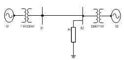 | Figure 2. Transient stability of a two-machine power system with and without PSS |
(PSS) used to improve the oscillatory damping of the system. Using MATLAB-Simulink, the generators were connected to a load centre through a long 330-kV, 700-km transmission line modeled by a resistive load.The machines were equipped with hydraulic turbine and governor (HTG), excitation system and power system stabilizer. Two types of stabilizers were connected on the excitation system: a generic model using acceleration power and multiband stabilizer using the rotor speed deviation
  .A faulty breaker block was connected at bus B1. A three-phase fault was applied at t = 0.1 s and cleared at t = 0.2 s. the results are discussed in Section VI
5. Transient Stability Analysis of Multimachine (Nigerian 330-kV Electrical Network)
Mathematical model of multimachine transient stability analysis are discussed in[14]. In this investigation, Nigerian 330 kV power system was considered. The network comprises 7 equivalent generators, 26 buses as shown in Fig. 3. Assuming machines belonging to the same station swing together and are said to be coherent. A group of coherent machines is represented by one equivalent machine. Kainji generating station served as the reference station with an output of 325-kV as at 26th July, 2010[15].A program was written in MATLAB package[16] which allowed analyzing transient stability of a multimachine (Nigerian 330 kV electrical network) subjected to a balanced three-phase fault. A program named trstab[14] was used for transient stability analysis of the network subjected to a balanced three-phase fault which was preceded by the power-flow program (ifnewton in this work). The generator data was specified in a matrix named gendata with the first column containing the generator bus number terminal, columns 2 and 3 containing resistance and transient reactance in per unit on the specified common MVA base and the last column containing the machine inertia constant in seconds expressed on the common MVA base.The program trstab automatically added additional buses to include the generator impedances in the power flow line data. The program displayed the pre-fault, faulted and post-faulted reduced bus admittance matrices. The machine phase angles were tabulated and plots of the swing curves were obtained and shown in Table 1 and Fig. 4. The simulation was carried out for clearing time of 0.2 and 0.7 seconds. When the faults in buses 5 (representing Shiroro generating station) and 17 (Benin transmitting station) were cleared which involved the removal of the faulty lines 5-10 (Shiroro-Katampe line) and 17-19 (Benin transmitting station-Sapele generating station) respectively, the bus admittance matrix was recomputed to reflect the changes in the network.Next, the postfault reduced bus admittance matrix was evaluated and postfault electrical power of the ith generator shown . The simulation continued to determine the system stability, until the plots in Figs 4 and 5 revealed a definite trend as to stability or instability. The slack generator taken as generator 1 connected to bus 1, as shown in Fig. 2, was selected as the reference for both cases, and the phase-angle difference of all other generators with respect to the reference machine were plotted as shown in Figs 4 and 5. The solution was carried out for two swings to show that the second swings were not greater than the first one. In figures 3.0 (a) and 4.0 (a), the angle differences did not increase; hence, the system was stable, while in figures 3.0 (b) and 4.0 (b), the angle differences increased indefinitely showing that the system was unstable. Having established 0.2 seconds as the critical clearing time of the system, PSSs were included on the excitation system to damp the rotor oscillations on the 7 equivalent generators using speed deviation as inputs. The damping effect of PSS is shown in Fig 6.
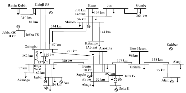 | Figure 3. Nigerian 330-kV Electrical Network |
6. Simulation Results
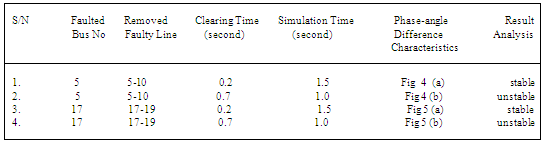
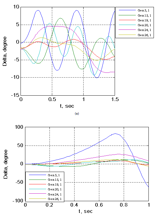
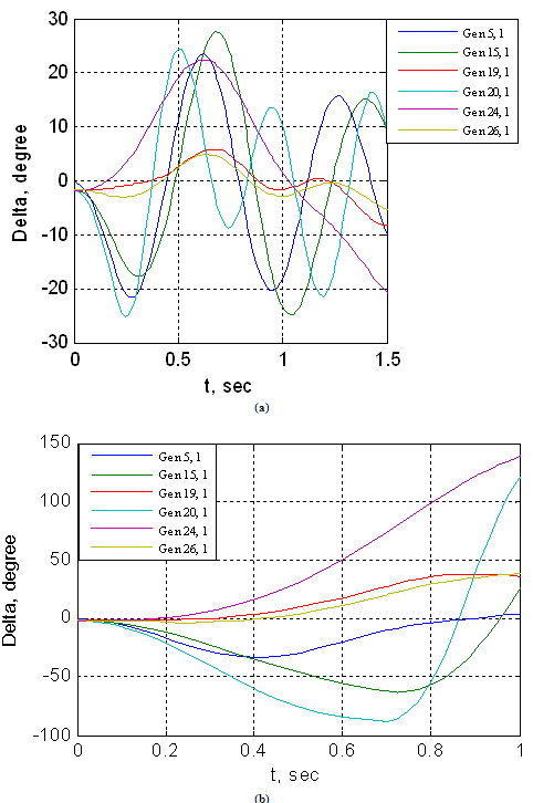
A. Simulation Results of Nigerian 300 kV Electrical NetworkThe results of the transient analysis carried out on Nigerian 330-kV electrical network with and without PSS are discussed in this section.Table 1. The Machine Phase Angles Characteristics and Analysis of Result
 |
| |
|
 | Figure 4. The generators phase-angle differences for Nigerian 330-kV electrical network (without PSS) for (a) three-phase fault on line 5-10 ( ) and (b) three-phase fault on line 5-10 ( ) and (b) three-phase fault on line 5-10 ( ) ) |
 | Figure 5. The generators phase-angle differences for Nigerian 330-kV electrical network (without PSS) for (a) three-phase fault on line 17-19  and (b) three-phase fault on line 17-19 ( and (b) three-phase fault on line 17-19 ( ) ) |
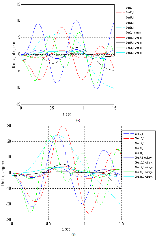 | Figure 6. The generators phase-angle differences for Nigerian 330-kV electrical network (with and without PSS) for (a) three-phase fault on line 5-10  and (b) three-phase fault on line 17-19 and (b) three-phase fault on line 17-19  |
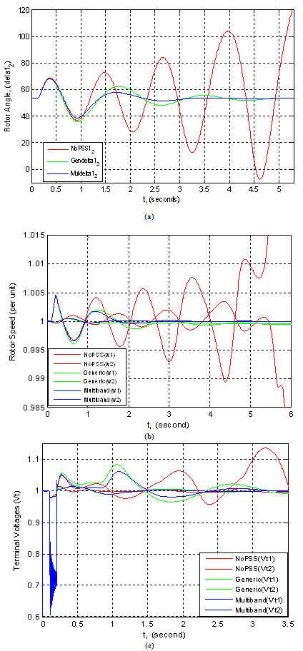 | Figure 7. Plots of two-generators connected to a load using two types of PSS showing (a) rotor angles, (b) rotor speeds and (c) terminal voltages all against time |
B. Simulation Results of Two Machines connected to a LoadFig. 7 (a) show the trace of the rotor angle difference (delta 1_2) between the two machines at three conditions: when multiband PSS was used, inclusion of generic and the exclusion of PSS. The multiband and generic signals are a good indication of system stability. If delta 1_2 exceeds 90 degrees for too long a period of time, the machines will lose synchronous and the system goes unstable.The second trace (b) in the figure shows the machine speeds. It was observed that machine 1 speed increases during the fault because during this period its electrical power is lower than its mechanical power. By simulating over a period of time (say 5 seconds), it was observed that the speed oscillated together at a lower frequency (0.025 Hz) after fault clearing. The two PSSs succeeded to damp the 0.6 Hz mode, but  types were not sufficient for damping the 0.025 Hz mode. Selecting the multiband PSS, it was noticed that this stabilizer type succeeds to damp both the 0.6 Hz and 0.025 Hz modes. But when the two PPSs were disabled, it was observed that the system was unstable. The same is applicable to Fig 7 (c) for terminal voltage trace.C. Eigenvalues and Damping Ratio Analysis of Single Machine connected to an Infinite Bus using Tabu Search ApproachA single machine connected to an infinite bus through a transmission line and operating at three different loading conditions was considered.This program generated random values for
  and
and  between 0.03 and 1.0 while it generated random values for
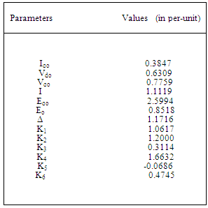
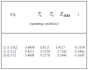
  between 0.01 and 10. Each generated value was substituted into the machine’s matrix to find the PSS parameters that adequately tuned the system. Tables 2, 3 and 4 show the parameters used for three different operating conditions, while Table 5 shows the outputs of the analysis carried out for the three operating conditions:
  ,
, and
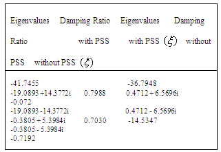
and  With AVR only, the eigenvalues are shown in Table 6 having a damped frequency,
  Hz and damping ratio
  The system became unstable through an oscillatory mode of
  Hz. The two non-oscillatory modes are associated with the AVR and field circuit.With the addition of PSS, the system had become stable. There are two oscillatory modes: one is the rotor angle mode with a frequency of
  Hz and the other has a frequency of 2.288 Hz and is associated with the excitation system and field circuit. The two non-oscillatory modes are associated with the excitation system. The improved damping ratios are 0.703 and 0.7988 respectively.
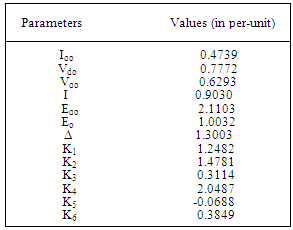
Table 2. Parameters for Operating Condition: P=1.0 and Q=0.2
 |
| |
|
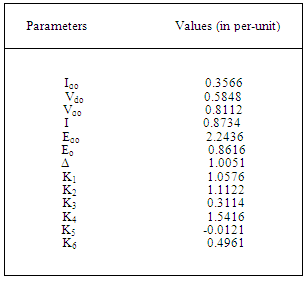
Table 3. Parameters for Operating Condition: P=0.8 and Q=0.5
 |
| |
|
Table 4. Parameters for Operating Condition: P=1.0 and Q=0.62
 |
| |
|
Table 5. The Output of the Analysis
 |
| |
|
Table 6. Eigenvalues and Damping Ratio Values
 |
| |
|
7. Discussion of Results
The results showed that for the second system considered, without PSS, the generators oscillated together in speeds at a low frequency after fault clearing. The two PSS (generic and multiband) succeeded to damp 0.6 Hz mode, but the former was unable to provide sufficient damping to 0.025 Hz mode. Furthermore, in the first investigated system, the program generated random values for PSS-parameters  and
and  between 0.03 and 1.0, while it generated random values for
  between 0.01 and 10. With AVR alone connected to the generator, the damped frequency
  and damping ratio
  were 1.046 Hz and -0.072 respectively. The system was unstable through an oscillatory mode of.
  Hz. The two non-oscillatory modes were associated with the AVR and field circuit. With the inclusion of PSS on the AVR, the system became stable. There were two oscillatory modes: one was the rotor angle mode with a frequency of 0.859 Hz and the other had a frequency of 2.288 Hz and their improved damping ratios were 0.703 and 0.7988 respectively. The transient stability analysis carried out on the Nigerian 330-kV electrical network showed that the inclusion of PSS on the generators helped damp the rotor oscillations of the generators, having established 0.2 seconds as the critical clearing time for the relaying systems.This study concluded that the introduction of PSS improved the damping of rotor oscillations which drastically reduced loss of synchronization and therefore improved power system stability.The effectiveness of the use of PSSs to enhance power system stability has been investigated. Three different power systems were considered: a single-machine connected to an infinite bus (SMIB), two machines connected to a load and multimachine system typified by the Nigerian 330-kV electrical network. The use of tabu search to design robust power system stabilizers for power system working at various operating conditions was investigated. The problem of selecting the PSS parameters, which simultaneously improve the damping at various operating conditions, was converted to an optimization problem with an eigenvalue-based objective function which was solved by a tabu search algorithm. An objective function was presented allowing the robust selection of the stabilizer parameters that placed the closed-loop eigenvalues in the left-hand side of a vertical line in the complex s-plane.The suggested robust design technique was successfully demonstrated on a single-machine infinite bus system operating at different loading conditions and was verified through eigenvalues analysis and simulation results.The damping effects of two types of PSS (generic and multiband) were also investigated on two machines, equipped with hydraulic turbine and governor (HTG) and excitation system, connected to a load centre through a long transmission line. By simulating over a long period of time (say 50 seconds), it was observed that the speed oscillates together at a lower frequency (0.025 Hz) after fault clearing.The two PSSs succeeded to damp the 0.6-Hz mode, but
  type was unable to damp the 0.025-Hz mode. Selecting the multiband PSS, it was observed that the stabilizer succeeds to damp both the 0.6-Hz and 0.025-Hz modes. But when the two PPSs were disabled, it was observed that the system was unstable. Lastly, the transient analysis on Nigerian 330-kV electrical network allowed assessing the system to be stable, unstable and also allowed determining the critical clearing time of power system with three-phase faults. These results can be used effectively in planning and operation of power systems.
8. Conclusions
The application of a Power System Stabilizer (PSS) for both small and moderate scale power systems has been explored in this study. The study includes the dynamic model of PSS to investigate its dynamic effect in damping unstable modes evolved as a result of the generators rotor angle or as excitation system interaction. Different simulation techniques as Matlab/Simulink and small signal stability analysis have proved the improvement of both voltage and system dynamic stability by including PSS controller signals in power system representation. The use of tabu search to design robust power system stabilizers for power systems working at various operating conditions is investigated in this paper. The problem of selecting the PSS parameters, which simultaneously improve the damping at various operating conditions, is converted to an optimization problem with an eigenvalue-based objective function which is solved by a tabu search algorithm. An objective function is presented allowing the robust selection of the stabilizer parameters that will optimally place the closed-loop eigenvalues in the left-hand side of a vertical line in the complex -plane. The suggested robust design technique was successfully demonstrated on a single-machine infinite bus system, and a multimachine power system, operating at different loading conditions. The performance of the robust PSS’s, tuned using the suggested technique, is verified through eigenvalue analysis and simulation results.
References
| [1] | Pai M.A. (1981) ´Power System Stability: Analysis by the Direct Method of Lyapunov´.North Holland Publishing Company, Amsterdam. |
| [2] | Kundur P. (1994). ‘Power System Stability and Control’. McGraw Hill, New York. |
| [3] | Awed-Badeeb, O.M. (2006). ‘Damping of Electromechanical Modes using Power System Stabilizers, Case: Yemini Electrical Network’. Journal of Electrical Engineering, Volume 57, No 5, 291-295. |
| [4] | Zhou, E.Z.; Malik, O. P. and Hope, G.S. (1991). ‘Theory and Method for Selection of Power System Stabilizer Location’. IEEE Transactions on Energy Conversion, Volume 6, Issue 1, pp 170-176. |
| [5] | Fleming, R. J.; Mohan, M.A. and Parvatism K. (1981). ‘Selection of Parameters of Stabilizers in Multimachine Power Systems’. IEEE Transactions on Power Apparatus and Systems, Volume 100, Number 5, pp 2329-2333. |
| [6] | Gooi, H. B.; Hill E. F.; Mobarak M. A.; Throne O. H. and Lee T. H. (1981). ‘Coordinated Multimachine Stabilizer Settings without Eigenvalue Drift’. IEEE Transactions, Volume 100, No. 8, pp 3879-3887. |
| [7] | Lefebvre S. (1983). ‘Tuning of Stabilizers in Multimachine Power Systems’. IEEE Transaction on Power Apparatus and Systems, Volume 102, Number 2, pp 290-299. |
| [8] | Lim C. M., and Elangovan, S. (1985). ‘Design of Stabilizers in Multimachine Power Systems, IEEE Proceedings, Volume 132; Number 3, pp 146-153. |
| [9] | Gibbard, M.J. (1991). ‘Robust Design of Fixed-parameter System Stabilizers over a Wide Range of Operating Conditions’. IEEE Transactions on Power Systems, Volume 6 Issue 2, pp 794-800. |
| [10] | Radman, G. (1992). ‘Design of Power System Stabilizer based on LQG/LQR Formulations’. IEEE Transaction on Industry Applications Society Annual Meeting, Volume 2, pp 1787-1792. |
| [11] | Xu, L. and Ahmed-Zaid, S. (1995). ‘Tuning of Power System Controllers using Symbolic Eigen-sensitivity Analysis and Linear Programming’. IEEE Transactions on Power Systems, Volume 10, Issue 1, pp 314-322. |
| [12] | Abido, M. A. and Abdel-Magid, Y.L. (2002). ‘Optimal Design of Power System Stabilizers using Evolutionary Programming.’ IEEE Transactions on Energy Conversion, Volume 17, Issue 4, pp 429-436. |
| [13] | Abido, M. A. and Abdel-Magid, Y.L. (2001). ‘Robust Design of Electrical Power-based Stabilizers using Tabu Search’. IEEE Power Engineering Society Summer Meeting, Volume 3, pp 1573-1578. |
| [14] | Glover, F. (1989). ‘Tabu Search: Part I, ORSA’. Journal on Computing, Volume 1, Number 3, pp 190-206. |
| [15] | Data collected from National Control Centre (NCC), Oshogbo, Nigeria on 28th July, 2010. |
| [16] | Saadat, H. (1999). ‘Power System Analysis’. McGraw-Hill International Editions. |
| [17] | The Math Works Inc., (www.mathworks.com) Using MATLAB and Simulink, 2007. |
 Abstract
 Reference
 Full-Text PDF
 Full-Text HTML