-
Paper Information
- Next Paper
- Previous Paper
- Paper Submission
-
Journal Information
- About This Journal
- Editorial Board
- Current Issue
- Archive
- Author Guidelines
- Contact Us
Electrical and Electronic Engineering
p-ISSN: 2162-9455 e-ISSN: 2162-8459
2012; 2(4): 208-216
doi: 10.5923/j.eee.20120204.06
The Performance of High Voltage Insulator Based on Epoxy-Polysiloxane and Rice Husk Ash Compound in Tropical Climate Area
 Abstract
 Reference
 Full-Text PDF
 Full-Text HTML
Arif Jaya 1, 2, Hamzah Berahim 3, Tumiran 3, Rochmadi 4
1Postgraduate Student in Department of Electrical Engineering and Information Technology, Yogyakarta,55281, Indonesia
2Department of Electrical Engineering, Moslem University of Indonesia, Makassar, Indonesia
3Department of Electrical Engineering and Information Technology, Gadjah Mada University, Yogyakarta,55281, Indonesia
4Department of Chemical Engineering, Gadjah Mada University, Yogyakarta,55281, Indonesia
Correspondence to: Arif Jaya , Postgraduate Student in Department of Electrical Engineering and Information Technology, Yogyakarta,55281, Indonesia.
| Email: |  |
Copyright © 2012 Scientific & Academic Publishing. All Rights Reserved.
This paper presents the effect of natural aging upon the performance of the polymeric insulation materials made from Epoxy resins, Polydimethylsiloxane (PDMS), and Rice husk ash compound. The samples of epoxy resin insulation material consist of Diglycidyl Ether of Bisphenol A (DGEBA), Meta Phenylene Diamine (MPDA) as curing agent, and 325 mesh Rice Husk Ash (RHA) as filler, treated with variation of PDMS content. The research aims are to observe the Equivalent Salt Deposit Density (ESDD), critical leakage current, and flashover voltage on the insulation material surface that has undergone a natural aging. Experimental method was carried out through the following procedure. The samples were placed outdoor for natural aging test, outside the building of electrical engineering and information technology of Gadjah Mada University in Indonesia. Then the ESDD, critical leakage current, flashover voltage on the sample surface was measured every 2 weeks. The experiment results show that the performance of insulator material fluctuates during 52 weeks. The higher PDMS with RHA filler content the lower ESDD and surface leakage current. Furthermore the flashover voltage increases.
Keywords: Epoxy-polysiloxane, Rice Husk Ash, Equivalent Salt Deposit Density, Critical Leakage Current, Flashover Voltage
Article Outline
1. Introduction
- The use of epoxy resins as high voltage insulator material is appropriate, because of its high dielectric strength (25-45 kV/mm)[1]. But epoxy resin insulating materials is very sensitive when used in areas with high temperature, high humidity, the existence of pollutants and ultraviolet radiation[2]. The main advantages of epoxy resin over porcelain material as insulator material are that it is much lighter (because of low density), easy handling, easy blending with additives, and having hydrophobicity.Many researchers revealed that the first generation polymer insulator material of epoxy resin based on bisphenol A with silica sand filler for outdoor insulators had satisfactory performance in normal air conditions. But, for long term outdoor service, their performance was unsatisfactory. There was a crack on the surface because it was not resistant to ultraviolet radiation[3]. The next generation is the cast epoxy resin cycloaliphatic. It shows good performance under normal atmospheric condition, but the performance will be decreased under polluted atmospheric condition[4,5]. The weakness of the cast epoxy resin cycloaliphatic is the impurity of its filler, Alumina Trihydrate (ATH), which may consist of Natrium Oxide (Na2O) and Kalium Oxide (K2O). Those two alkali oxide along with water will form Alkali Hydroxyl (NaOH and KOH), a strong electrolyte, which can change dielectric property of cast epoxy resin cycloaliphatic[6].An aging test to analyze Silicon Rubber (SiR) type polymeric polysiloxane insulator and Ethylene Propylene Diene Monomer (EPDM) insulator performance was held outside Anneberg Bulk Station, West Coast Sweden by observing the relationship between surface condition and performance of polymeric insulator. Six SiR and three EPDM samples were analyzed by using Electron Spectroscopy for Chemical Analysis (ESCA), Attenuated Total Reflection Fourier Transform Infrared (ATR-FTIR), and Scanning Electron Microscopy (SEM). The results conclude the relationship between insulation material surface condition and hydrophobic property, leakage current and voltage resistance. In EPDM insulator, a high magnitude of leakage current and intensity of arc occurs. But, in insulator of SiR only a very low leakage current occurs.Polysiloxane (i.e. silicon rubber) is able to create hydrophobic properties on insulator surface in which prevents water layer formation and leakage current occurrence on its surfaces. Low Molecule Weight (LMW) component is diffused from the bulk of SiR to the outer surface layer. LMW will then film the pollutant and maintain the hydrophobic properties (i.e. prevent water layer formation on insulator surface)[8].Adding ATH to SiR gives better resistance of erosion and tracking. Surface degradation of elastomeric silicon with lower filler (0-25%) will make tracking phenomenon occurs faster, while higher filler (50%-70%) will delay surface degradation due to dry band arc phenomenon and reduce water absorption[9].The application of polysiloxane on the mixture of epoxy and rice husk ash as the filler affects the hydrophobic properties. The higher filler content in insulator the bigger contact angle of water droplets on the insulator surface[10].Insulator contaminations become a troublesome in electrical power system operation. Wet atmospheric condition will form thin water layer on the insulator surface. Then, the present of the contaminant inside the layer will create leakage current on the insulator surface[11]. The contaminant layer accumulation at the surface of the insulator will increase the leakage current in which causes flashover voltage and give damage to insulator[12].Considering that electrical properties of polymeric insulators are influenced by the type of material and the environmental conditions, therefore this paper will discuss performance of epoxy-polysiloxane polymeric insulator materials with rice husk ash as the filler (EP-RHA) under natural tropical climate. The performance is measured as equivalent salt deposit density, surface leakage current, and the flashover voltage.
2. Epoxy - Polysiloxane Polymeric Insulator
2.1. Epoxy Resin Polymeric Insulator Material
- Epoxy is a thermosetting chemical compound. It consists of oxygen and carbon atomic bond which is generated by chemical reaction between epichlorohydrin and bisphenol A. A complex structure of epoxy resin has molecule bond as shown in Fig.1.
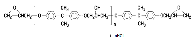 | Figure 1. Epoxy resin structure |
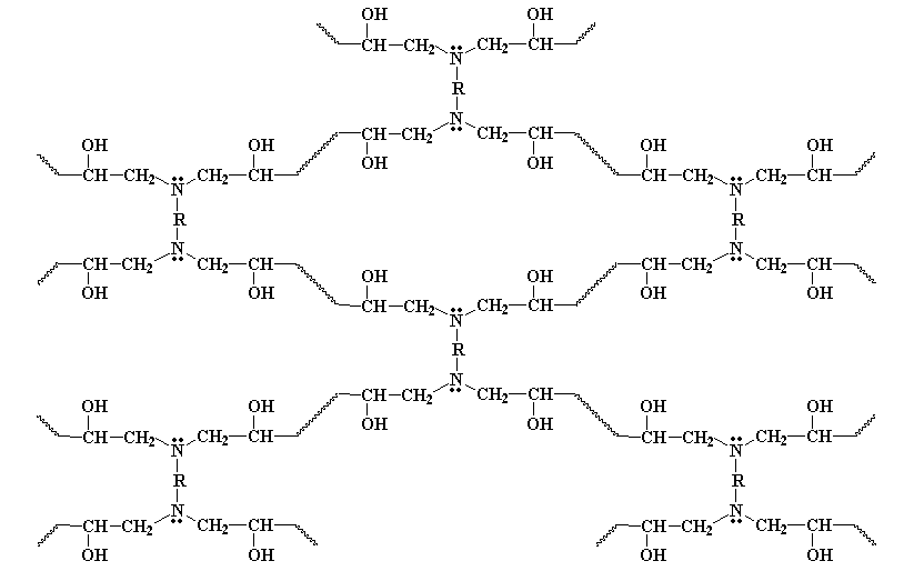 | Figure 2. Epoxy resin formation reaction with MPDA hardener |
2.2. Polysiloxane Polymeric Insulator Material
- Polysiloxane is a polymeric material that consists of silicon and oxygen atom on its main chain. Polysiloxane main chain is more flexible than vinyl polymeric and polyolefin. The chemical structure of polysiloxane is shown in Fig. 3.
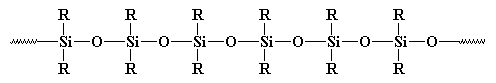 | Figure 3. Chemical structure of Polysiloxane |
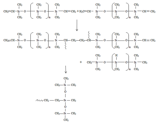 | Figure 4. Addition polymerization reaction process resulting PDMS |
2.3. Rice Husk Ash
- In Indonesia, rice husk is usually used for main firing material (fuel) in brick industry or as plant seed medium, while its ash is usually used for cleaning-rub ashes or even wasted. Rice husk burning will produce RHA with very high SiO2 content (>80% from total weight). When continuous burning at 500 to 700℃ for 1-2 hours applied, RHA will contain large amount of amorphous silica which can increase mechanical property of cement-RHA mixture at certain dosage[15,16].
3. Insulator Material Performance
3.1. Equivalent Salt Deposit Density (ESDD)
- The outdoor insulator surface will be contaminated by pollutant which is carried by the wind. Pollutant materials basically divided as 2 major components: conductive components and inert components. The conductive components mostly consist of ionic salt such as sodium chloride (NaCl), sodium sulphate (Na2SO4), magnesium chloride (MgCl2), etc. Inert components are a solid materials or cations which can not being unravelled to ions in liquid (e.g. kaolin, silica, bentonite, cement, etc). These inert components can create mechanical bond with conductive component particles. Kaolin, cement dust and silica make the insulator surface become hydrophilic, while oil creates hydrophobicity.
|
 | (1) |
 | (2) |
 | (3) |
 | (4) |
 | (5) |
3.2. Leakage Current on Insulator Surface
- Most of high voltage insulator applied outdoor in electrical power transmission systems. Polluted environment will create a long term pollution coating on insulator surface. This pollution coating does not have a detrimental effect when the insulator is dry. The electrostatic field determines the voltage distribution of such a dry insulator and a very small capacitive leakage current flow across the entire insulator. However in the atmospheric condition is wet, the contamination particles on the insulator surface will dissolve into the water and provide a continuous path of conduction between the high voltage electrode and ground.When an insulator is wet, a resistive leakage current flows in a conducting path on the insulator surface which has greater value than capacitive current (in case the insulator is in dry condition). At this point, the equivalent circuit can be represented by resistance (Rw). This leakage current creates in non-uniform heating of the contamination layer that eventually causes dry bands to be formed at the narrow sections where the surface leakage current density is highest.The voltage distribution along the surface of wet polluted insulators is very non-uniform when a dry band is formed in series with the conductive film. Since the resistance of the dry band is very high, the whole applied voltage across the insulator appears across the dry band. As a result, the breakdown occurs across the dry band when it reaches the air critical flashover voltage and generates small sparks between the separating moisture films.The heat resulting from the small sparks creates carbonization and volatilization on the insulator surface which left permanent carbon tracks on the surface. This process will continue until the breakdown happen due to the formation of carbon bridge between electrodes[18]. This phenomenon is usually occurs in wet contaminated insulator surface. The equivalent circuit after the appearance of dry band is represented by parallel resistance (Rd) and a capacitor (Cd). The leakage current phenomenon on the insulator surface and its electrical model is shown in Fig. 5.
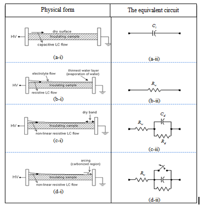 | Figure 5. Leakage current phenomenon on insulator surface and its electrical model |
 | (6) |
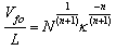
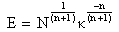
 = electric field (kV/cm); (Ilc) = leakage current (mA); N = constant which is related with electric field; n = constant which is related with leakage current.
3.3. Flashover Voltage on Insulator Surface
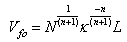
- Flashover voltage is an external disturbance on insulator surface or fire arcing process on insulator surface. It may occur in solid surface or gas. Flashover voltage value is smaller than puncture voltage on an insulator. Several factor affect flashover voltage, such as: surface resistance of a material, surface condition and electric field shape between electrodes and insulator.Flashover voltage on polluted condition follows this following sequence[19,20]:1) Insulator with dry band and conductive pollution layers are represented as a series of arc path along x (air gap) and resistance of polluted layer at every length unit R’=R’(I), as in Figure 6.2) The surface of insulator between two electrodes is an electric arc which is in series with conductive polluted layer.3) The arcing can extend or shut-off if the electric field strength reaches certain value in dry band, then the electric discharge occurs and initiates flashover.4) Flashover voltage occurs when the arc covers entire dry band and further the entire insulator surface between two electrodes.
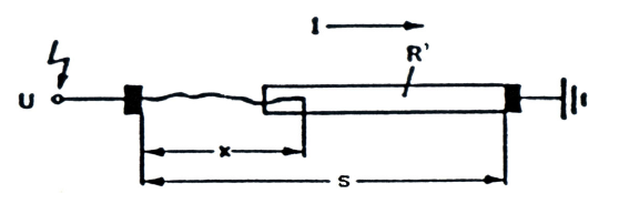 | Figure 6. Model of insulator with dry band and contaminated layer to determine critical leakage current (I) and voltage (U) |
 | (7) |
 | (8) |
 | (9) |
 | (10) |
 | (11) |
4. Experimentation
4.1. Materials and Testing Tools
- The materials used in this experimentation consist of: 1) Epoxy resins, with the basic material is Diglycidyl Ether of Bisphenol A (DGEBA) and hardener is Meta Phenylene diamine (MPDA) (brand name: Eposchon); 2) Silicon Rubber (SiR), type: RTV 585 with catalyst code: 60R (chloroplatinic acid) (brand name: Rhodorsil); 3) Rice husk ash, 325 mesh, type: IR 64, as filler material.Test sample was made in round shape with 70 mm diameter and 5 mm thickness, and coded as: RTVEP1(filler 10%),RTVEP2(filler 20%), RTVEP3(filler 30%), RTVEP4(filler 40%), and RTVEP5(filler 50%).The testing tools consist of: 1) Fog chamber with size of 1.2 x 1.2 x 1.2m as testing chamber; 2) High voltage apparatus, transformer 220/100000 volt, 5 kVA, 50 mA current, 4% impedance, 50/60 Hz; 3) Thermometer for temperature, hygrometer for humidity and barometer for air pressure measurement; 4) Oscilloscope, LeCroy 9354 AL, 500 MHz; 5) Conductivity meter, Hanna Instrument HI8633. All tools are available in the High Voltage Laboratory, Electrical Engineering and Information Technology, Gadjah Mada University, Yogyakarta, Indonesia.
4.2. Testing Procedure
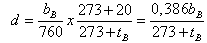
- The test samples are installed outdoor, outside Electrical Engineering building, Gadjah Mada University. Samples are placed in support bracket with 45 tilt, flipped every week and taken for performance test every 2 weeks. This procedure applies for 52 weeks experiment period. The ESDD procedure will follow these steps: 1) Preparing a beaker, measuring cup, and cleaning cotton; 2) Filling a beaker with 200 ml distilled water; 3) putting the cotton inside the beaker, measuring the temperature and conductivity; 4) Separating the pollutant layers from the samples by rubbing the soaked cotton, then putting the pollutant and the cotton into the beaker, and finally stirring them; 5) Measuring the temperature and conductivity of water and cotton mixture. The conductivity with and without pollutant are conversed into standard conductivity at 20℃ by using b factor based on IEC 507 standard (1991), then calculating salt concentration (in %) by using equation (2). The ESDD can be calculated the by using equation (3).Leakage current measurement procedure can be explained as following steps: 1) Putting test sample into fog chamber with 70% humidity (after fogging); 2) Applying voltage. Every sample is tested by applying increase voltages with a step of 1.5 kV/sec, from 11.5 kV up to 50% flashover voltage; 3) Recording. Every surface leakage current displayed and recorded by an oscilloscope; 4) Multiplying the voltage value from the oscilloscope with multiplying factor of voltage divider equivalent for obtaining leakage current value; 5) Calculating critical surface leakage current.Flashover measurement procedure can be explained as following steps: 1) Putting test samples into fog chamber with 70% humidity (after fogging); 2) Applying voltage. Every sample is tested by applying increase voltages with a step of 1.5 kV/sec until flashover occurs; 3) Recording temperature, humidity and air pressure then converting flashover voltage value by using standard value correction factor (as eq. 10 and eq. 11). The measurement tools arrangement is shown in Fig. 7.
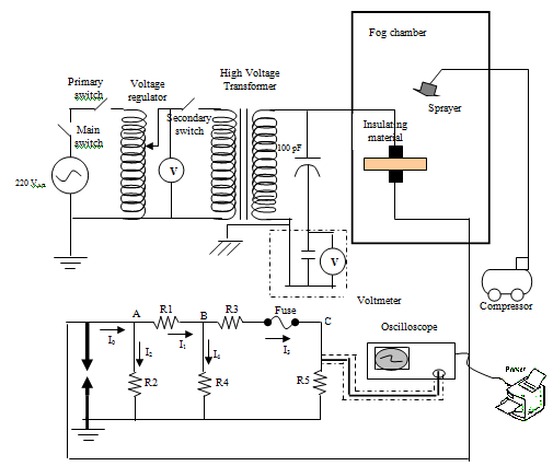 | Figure 7. The measurement tools arrangement for leakage current and flashover voltage test |
5. Results and Discussion
- The following sections below show the performance results of insulator materials of epoxy-polysiloxane with rice husk ash filler for each composition during 52 weeks experimentation.
5.1. ESDD Performance of Epoxy-polysiloxane Polymeric Insulator with Rice Husk Ash Filler
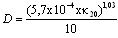
- Fig. 8 shows the results of ESDD of EP-RHA insulator in each composition against natural aging. The experiment period is 52 weeks. It is calculated by using equation (3).ESDD value of EP-RHA insulator material with various compositions is fluctuating during the aging process. This phenomenon happened due to variation of composition and local climate condition during the test. The highest the filler composition the lower the ESDD value is. The increase of filler material then makes methyl group (CH3) on insulator surface also increases. This makes the insulator material more hydrophobicity[10]. When there is a rain, the EP-RHA insulator surface will be wiped up by the water. This hydrophobic property will decrease the ESDD and surface leakage current, so the power losses will be decrease as well[20]. Fig. 8 shows ESDD value from initial aging until week 12th which fluctuates and tends to increase (Nov 2010 to Jan 2011). It is because of the tropical climate with low rain intensity. From week 14th to 28th (Feb - May 2011), the ESDD value of EP-RHA insulator surface tends to decrease due to high rain intensity (rainy season). From week 30th to 44th (Jun – Sep 2011), the ESDD tends to increase due to entering summer season. From week 46th to the end of week 52nd (Sep-Nov 2011), the value of ESDD decreases due to beginning of rainy season.
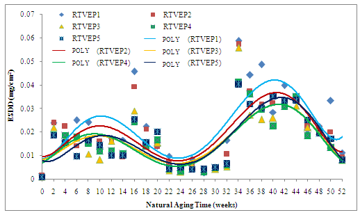 | Figure 8. ESDD value against duration of aging for various filler composition in 52 weeks natural aging |
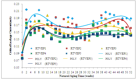 | Figure 9. Critical leakage current on insulator surface for various filler composition in 52 weeks natural aging |
5.2. The Critical Leakage Current Performance of Epoxy-polysiloxane Polymeric Insulator with Rice Husk Ash Filler
- The Fig. 9 shows the two dimensional results of critical leakage current of EP-RHA insulator in each composition against natural aging. The experiment period is 52 weeks. The critical leakage current values of EP-RHA insulator material with various compositions are fluctuating during the aging process. These values have the same trend with fluctuating value of ESDD. The higher ESDD the higher critical leakage current is, as shown in Fig. 10. The natural atmospheric condition covers those EP-RHA insulators with pollutants. The pollution layer increases the conductivity on the insulator surfaces. In wet atmospheric condition, the salt component in the pollution layer will dissolve in the water which is a form of electrolyte.As the result, the EP-RHA insulator surfaces become conductive, and therefore the leakage current flows on its surface. The higher ESDD the higher the conductivity is on the EP-RHA insulator. The higher conductivity, the higher surface critical leakage current is. The filler material is measured in percentage of overall composition. The higher filler composition the lower the ESDD is. For example in case of 10% composition (RTVEP1) the average ESDD is 0.0226 mg/cm2. In the other hand in case of 50% composition the average ESDD is 0.0171 mg/cm2.
| |||||||||||||||||||||||
5.3. The Flashover Voltage Performance of Epoxy-polysiloxane Polymeric Insulator with Rice Husk Ash Filler
- The flashover voltages of EP-RHA insulator material with various compositions are fluctuating during the aging process (52 weeks) as shown in Fig.11.The standard flashover voltage for EP-RHA insulator with various compositions tends to decrease until week 52nd. The standard flashover voltage is affected by the ESDD value and surface leakage current. The ability of an insulator to withstand surface voltage is affected by pollution layer and surface wetting phenomenon[22]. In wet condition, a contaminant layer is formed on the surface, so that the insulator surface is conductive properties. The surface conductivity will increase if the surface pollution layer is thicker. This make the leakage current increase, so that the leakage current creates in non-uniform heating of the contamination layer that eventually causes dry bands. The insulator surface between both electrodes is a form of dry band arcing that series connected with a conductive pollutant layer[19,20]. The dry band arcing can extend or shrink/vanish. When the electric field strength reaches certain value in dry band, then the surface electric discharge occurs, initiates a flashover voltage on the EP-RHA insulator surface. The higher filler content in EP-RHA insulator, the lower the ESDD and the critical leakage current. If the ESDD and the critical leakage current are decreased, then the flashover voltage is increased.
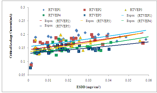 | Figure 10. Critical surface leakage current against ESDD value for various filler composition |
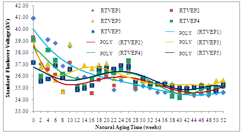 | Figure 11. Standar flashover voltage against duration of aging for various filler composition in 52 weeks natural aging |
| |||||||||||||||||||||||
6. Conclusions
- The performances of ESDD, critical leakage current and standard flashover of epoxy-polysiloxane polymeric insulator material with rice husk ash filler (EP-RHA) are fluctuating depend on local climate where the experiment is held.During natural aging, the higher filler content in EP-RHA insulators results the lower value of ESDD and critical leakage current. If the ESDD and the critical leakage current are decreased, then standard flashover voltage is increased.The performance measurements of EP-RHA insulator for each composition are (in average value), RTVEP1: ESDD = 0.0226 mg/cm2, Ilc = 0.1782 mA, Vfo = 35.867 kV; RTVEP2: ESDD = 0.0195 mg/cm2, Ilc = 0.01653 mA, Vfo = 35.541 kV; RTVEP3: ESDD = 0.0166 mg/cm2, Ilc = 0.1556 mA, Vfo = 36.017 kV; RTVEP4: ESDD=0.0164 mg/cm2, Ilc = 0.1460 mA, Vfo = 35.827 kV; and RTVEP5: ESDD = 0.0171 mg/cm2, Ilc = 0.1325 mA, Vfo = 35.741 kV.
ACKNOWLEDGEMENTS
- The authors would like to say thank you to Mr. Daryadi and Mr. Prasetyohadi as laboratory assistant of High Voltage laboratory, Electrical Engineering and Information Technology, Gadjah Mada University for their assist during this experiment completion.
References
| [1] | G. G. Raju, Dielectris in Electric Fields, Volume 19: Power Engineering series ed, Marcel Dekker Inc,New York, 2003. |
| [2] | K.J. Saunders, Organic Polymeric Chemistry, John Wiley & Sons, New York, 1973. |
| [3] | N.H. Malik, A.A. Al-Arainy, and M.I. Quresshi, Electrical Insulation in Power System, Volume 3: series ed, Marcel Dekker Inc, New York,1998. |
| [4] | E.A. Cherney, “Non ceramic insulator. a simple design that requires careful”, IEEE Electrical Insulation Magazine, vol .12, pp. 7-15,1996. |
| [5] | Kahar, Nes Yandri.,“Penelitian Tentang Epoksi Sikloalifatik Tuang (EST) Sebagai Bahan Isolasi Listrik Tegangan Tinggi Di Daerah Beriklim Tropis”, P.hD. Disertasi, Institut Teknologi Bandung, Indonesia,1998. |
| [6] | G.E., Mortiner, “Chemie”, George Thieme Verlag, Stuttgart. 1983. |
| [7] | Sorqvist, U. Karlson, A.E. Vlastos, “Surface ageing of polymerics insulator”, IEEE Trans. On Pow. Delivery, vol .5, pp. 406-414, 1995. |
| [8] | J.P., Reynders, I.R., Jandrell, S.M., Reynders, ”Review of Agingand Recovery of Silicon Rubber Insulation for Outdoor Use”, IEEE Transaction on Dielectrics and Electrical Insulation, Vol.6,no.5,pp. 620-631, 1999. |
| [9] | S.H. Kim, S.H. E.A. Cherney, and R. Hackam, “Effects of Filler level in RTV silicon rubber coating used in HV Insulator”, IEEE Trans. On Pow. Delivery, 1992. |
| [10] | Jaya, A., Berahim, H., Tumiran, Rochmadi, “The Hidrophobicity Improvement of High Voltage Insulator Based on Epoxy-Polysiloxane an Rice Husk ash”, Proceedings of The International Conference on Electrical Engineering and Informatics,pp.1231-1236, 2011. |
| [11] | E.A.,Cherney, R.,Hackam, and S.H.,Kim, “Porcelain Insulator Maintenance With RTV Silicone Rubber Coatings”, IEEE Trans. On Pow.Delivery.,vol. 6,no.3,pp. 1177-1181,1991. |
| [12] | GuoxiangXu., and P.B., McGrath, “Electrical and Thermal Analysis of Polymeric Insulator under Contaminated Surface Condition”,IEEE Trans. on Dielectrics and Electric. Insul., vol. 3,no.2,pp. 289 – 298,1996. |
| [13] | C Burger, W.R Hertle, P.Kochs, F.H. Kreuzer, and H.R. Krichedorf, Silicone and Polymeric Synthesis, Springer Hamburg, Germany, 1996, |
| [14] | D. Kind, H.C. Kaerner, High Voltage Insulation Technology, Textbook for Electrical Engineers, Friedr Vieweg & Sohn, Braunschweig/Wiesbaden, 1985. |
| [15] | H. Onggo., “Proses Dan Sifat Campuran Abu Sekam Semen”, Telaah, vol. 9, pp. 27-38, 1986. |
| [16] | Priyosulistyo., Sumardi., Sudarmoko., Bambang Suhendro, Bambang Supriadi, “Pemanfaatan Limbah Sekam Padi untuk Meningkatkan Mutu Beton, Teknik Sipil, UGM Yogyakarta, 2004. |
| [17] | Artificial Pollution Test on High-Voltage Insulator to be used on AC Systems, Second Edition, Geneva. IEC Std 507, 1991. |
| [18] | M.S.Naidu, V. Kamaraju, High Voltage Engineering. Tata McGraw-Hill Publishing Company Limited, New Delhi.1987 |
| [19] | F. Obenaus, ”Fremdschict Uberschlang Und Kreischweglange”, Deutche Electrotechnik, Vol. 4, pp. 135-136.1985. |
| [20] | Y. Mizuno., H. Kusada., Naito, K., “Effect of Climate Conditions on Contamination Flashover Voltage of Insulators”,IEEE Trans. on Pow. Delivery., Vol.10.no.3, pp.1378-1383. 1997. |
| [21] | High Voltage Test Techniques, Second Edition, IEC Std 601,1989. |
| [22] | G.G. Karady, Shah, M., and R.L.,Brown, “Flashover Mechanism of Silicon Rubber Insulators used for outdoor Insulation – I”, IEEE Trans. on Pow. Delivery., vol.10,no.4, pp. 1965-1971, 1995. |