M. Asadi 1, 2, A. Jalilian 2, 3
1Industrial electronic department of Niroo Research Institute (NRI), Tehran, Iran
2Electrical Engineering department of Iran University of Science and Technology (IUST), Tehran, Iran
3Center of Excellence for Power System Automation of Operation, Tehran, Iran
Correspondence to: M. Asadi , Industrial electronic department of Niroo Research Institute (NRI), Tehran, Iran.
| Email: |  |
Copyright © 2012 Scientific & Academic Publishing. All Rights Reserved.
Abstract
Parallel passive filters are used for decrease of harmonic components of load currents. In electrical distribution systems, over voltages such as switching and lightning over voltages are applied to the parallel passive filters. This paper analyses the behaviour of parallel passive filter employed to decrease the load harmonic currents under travelling wave conditions. The parallel passive filter is vulnerable to lightning surges. Therefore, protection of it against lightning surges is necessary. Equipment protection against lightning surges is usually done by gapless surge arrester. This paper presents important points of gapless surge arrester to protect parallel passive filters. Also an algorithm is presented to select gapless arrester under harmonic conditions in this paper. The presented algorithm is based on the IEEE standards C62.22 and 1531. Finally the simulation results are provided to verify the presented algorithm.
Keywords:
Parallel Passive Filter, Lightning Surge, Gapless Surge Arrester, Travelling Wave, Harmonic Component, Electrical Distribution Systems
1. Introduction
Discharges of lightning surges on electrical distribution lines cause electrical breakdown of insulators. Sometimes cutting of the electrical line and outage are occurred because of lightning discharges. Concrete poles utilized in low voltage electrical systems (up to 20kV) have no grounding systems and no grounding conductors. Therefore, they cannot suppress the lightening surges effectively due to their large surge impedances. Also probability of the simultaneous lightning discharges on three-phase system is high, because of short height of the insulators and shape of utilized cross arms in distribution systems.If the voltage magnitude of the lightning surge is higher than LPL (lightning protection level) of the insulators, the flashes are occurred on the insulators of three-phase. Chopped surges voltages which are produced by the flashes, travel through conductors named travelling waves[2]Today the parallel passive filters (PPFs) are widely used to decrease harmonic currents of non-linear loads in the electrical distribution system. Whereas number of the lightning surges is high, the protection of the PPFs is necessary. Design of the PPFs is based on limitation of the harmonic currents as mentioned in standard IEEE519[1] but the details of protection of the PPFs during lightning surges are not discussed in the standard. The surge arresters are used in installation of the PPFs to prevent failures of their components during lightning surges. If the PPFs are not protected appropriately, they will damage[2]. For example in HVDC transmission system, the arresters are employed to protect series capacitors[3]. In[4] various approaches are discussed to protect electrical equipment but they are not under harmonic conditions. The subject of[5] is estimation of heating with mixtures of fundamental and harmonic voltages in order to select an appropriate rating of arrester, but the paper does not examine effects of the lightening surges on parallel passive filters. Reliability of the PPF is important too, use of surge arresters for lightning protection improve reliability of the system[6]. This paper examines equivalent surge impedance in conjunction point to analyse behaviour of travelling wave in electrical distribution lines. Also the PPF is examined under travelling wave conditions in this paper. To selection of arrester, an algorithm is presented for protection of the PPF. The IEEE standards C62.22 and 1531 are employed to extract the algorithm. Finally a case study is simulated to verify the presented equations and algorithm. There are several model for analysis of the surge arrester, such as IEEE model, Pinceti model, Popov model[7], this paper uses IEEE model of the surge arrester in simulation.
2. Travelling Waves in Distribution System
To reduce the harmonic currents, the PPFs are utilized in 20kV or 0.4kV electrical systems. Where the PPFs are employed in 20kV electrical systems, they must be protected against the lightning surges by gapless arresters. The arrester is placed across passive filter or across capacitor of the parallel passive filter[2]. Figure (1) shows a simple electrical distribution system comprising a radial distribution line, a PPF and an arrester. Also the equal surge impedance of the electrical distribution system in conjunction point is shown in figure(1). When lightning surge hits on the line, tow travelling waves appear on the each phase of the electrical distribution line as shown in figure(1). Therefore, six travelling wave are appeared when lightning surge hits on the conductors. After conjunction, the lightning surges move towards the arrester and the filter through the conductors. In conjunction of lightning surges with the PPF and the arrester, the arrester should protect the PPF.A radial electrical distribution line without branches and ignoring of other loads is the worst case for analysis of the conjunction of lightning surges with electrical distribution line, as shown in figure(1).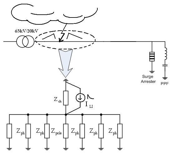 | Figure 1. Equivalent circuit of the worst case |
Figure(1) shows the equivalent circuit of conjunction point, where lightning surge hits on the conductors. In the conjunction point, the magnitude of the surge voltage can be written as: | (1) |
where VLI, ILI and Zeq denote lightning voltage, lightning current and equivalent surge impedance of conjunction point, respectively. Equivalent surge impedance will be: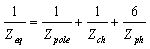 | (2) |
Where, Zpole is surge impedance of the concrete pole, Zch is surge impedance of the discharge channel of air, and Zph is surge impedance of the conductor.Lightning current(ILI) depends on the climate conditions, but the lightning voltage depends on the surge impedance and the lightning current wave form as seen in figure(2).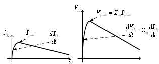 | Figure 2. The wave forms of current and voltage of lightning surge |
As mentioned, six voltage surges occur and travel along distribution line at a velocity of 300000 km/sec approximately. Figure(3) shows the distributed circuit of the distribution line of one phase which voltage surge travels along it. | Figure 3. distributed circuit of distribution line |
In figure(3), v(x,t) and i(x,t) are the voltage and the current at point x and time t, which is located at a distance of x from the conjunction point. In no-loss line(R=G=0), the equations of the travelling wave will be[8]: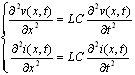 | (3) |
General solution of no-loss equations is: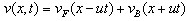 | (4) |
 | (5) |
Where Zo=(L/C)0.5 is the surge impedance Zph=ZO and u=(LC)-0.5 is the velocity of the wave which is 300000km/sec approximately in air distribution lines. Voltages vF and vB are named the forward and the backward waves respectively.When a travelling wave on a distribution line reaches the PPF, a part of the wave reflects back along the line, and another part passes to the PPF. Without protection, if the voltage magnitude of the lightning surge encountering to the PPF is larger than the base insulation level (BIL) of the PPF, the PPF will be damaged. To avoid parallel passive filter failure, there are two strategies:Decreasing of ZeqUtilizing of surge arresterTo reduce Zeq, grounding system is necessary to be installed for each pole, but this method is costive. Therefore, utilizing of the surge arrester is economic.
3. Behaviours of the PPF under Travelling Wave Condition
The behaviours of the travelling waves reaching to the PPF depend on the shapes of the waves and the values of the elements(L and C) employed in the PPF. The PPF behaves similar to capacitor where XC>>XL and behaves similar to inductor where XC<L[8].The PPF consists of a capacitor is connected in serries with an inductor. To examine behaviour of the PPF during travelling wave, it is needed to drive differential equations.To protect the PPF perfectly, investigation of the worst case is necessary too. Figure (4) shows the worst circuit of the PPF under the travelling wave condition.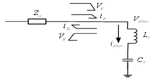 | Figure 4. The worst circuit of investigation of PPF behaviour under travelling wave condition |
From figure (5), it can be written as: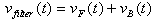 | (6) |
 | (7) |
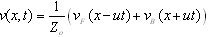
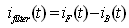
The filter current is equal to the capacitor current, so: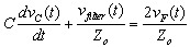 | (8) |
From equations(6-8), the capacitor voltage can be written as: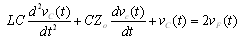 | (9) |
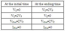
The behaviours of the PPF at the initial and ending times of travelling wave are shown in Table(I).Table 1. The behaviour of the PPF at the initial and ending times of travelling wave
 |
| |
|
Considering table(I), the voltages of the capacitor and the inductor will be two times of peak value of VF without protection. Therefore, it is necessary to protect the PPF against the travelling waves.
4. Selection of Surge Arrester under Harmonic Conditions for Protection of the PPF
Gapless arresters are used to protect the PPF. They utilize a single stacked column or two or more parallel columns of metal-oxide valve elements. Voltage-current characteristic and the structure of a gapless arrester are shown in Figure(5).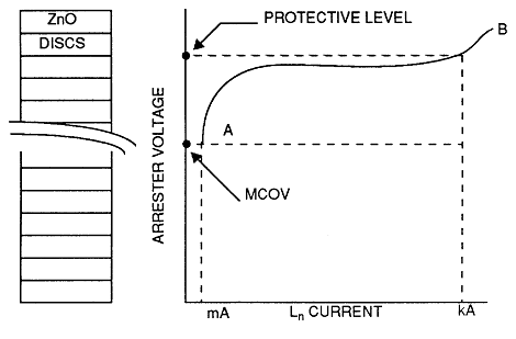 | Figure 5. VI characteristic and structure of gapless arrester |
The nonlinear behaviour of arrester can be approximated by: | (10) |
Where k is calculated by fitting of the curve, andnormally varies from 10 to 50 for metal-oxide[3].Three parameters are considered to select an arrester:• voltage rating• maximum continuous operating voltage(MCOV)• temporary overvoltage(TOV)The voltage rating of an arrester is determined by the manufacturer. The MCOV of the arrester is typically in the range of 75% to 85% of the voltage rating.To prevent activation of arrester in contingent over voltage such as load rejection, single phase short circuit or entrance of PPF, TOV of arrester should be greater than magnitudes short-time over voltages. | (11) |
If there are no voltage harmonic components, the arresters located at the line terminals of a PPF are applied in the same way as other arresters located on a power system. In the otherwise, the peak applied voltage and harmonic heating should be considered in selecting the arrester rating[2,9]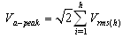 | (12) |
From equation(12), the peak voltage of the arrester(rated voltage) will be equalled to sum of the fundamental and the harmonic components.To prevent heating of the arrester, the maximum continuous operating voltage (MCOV) of the arrester should be higher than sum of the fundamental and the harmonic voltages[2,8].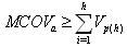 | (13) |
The harmonic (dielectric) heating of the arrester is proportional to the order of the harmonic and the square of the voltage of each harmonic (including the fundamental). To avoid heating of arrester dielectric at rated frequency, the arrester MCOV rating should be selected as[2,9]: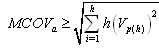 | (14) |
For continuous operation, the MCOV for arrester should be based on the higher value of equations (13) and (14).
5. Flowchart of Arrester Selection under Harmonic Conditions
Figure(7) shows the algorithm of the arrester selection under harmonic conditions. The steps of the flowchart are as follows:Step1: The elements of the PPFs are designed according to[1, 2].Step2: The harmonic voltages and the temporary over voltage are calculated by load flow.Step3: Vr, MCOV and TOV of the arrester are determined from equations (11) to (14).Step4:The insulation coordination is calculated as follows[2]:Degree of coordination is calculated by the protective ratio (PR):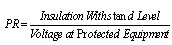 | (15) |
Three protective ratios are in common use which compare protective levels with corresponding insulation withstands.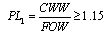 | (16) |
 | (17) |
 | (18) |
Where the following withstand levels for the PPF and the bus insulation are:Chopped Wave Withstand (CWW): a 1.2/50 µs surge is chopped by the action of a gap (arcing horn) Basic Lightning Surge Insulation Level (BIL): a full-wave 1.2/50 µs surges as specified in the PPF standard.Basic Switching Surge Insulation Level (BSL): BSL isn't usually used in distribution system.Front-of-wave protective level (FOW): The crest discharge voltage resulting from a current wave through the arrester of lightning surge classifying current magnitude with a rate-of-rise high enough to produce arrester crest voltage in 0.5µsLightning Protective Level (LPL): Magnitude of the discharge voltages is established by 8/20 µs discharge current surges.Switching Protective Level (SPL): The discharge voltage of switching surge is classified current at 45–60 µsStep5: The maximum allowable separation distance between the arrester junction and the PPF terminal is calculated as below:It is necessary to calculate acceptable separation distances between the arrester and the PPF. Equation (19) determines allowable distance(D)[2]: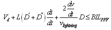 | (19) |
Where:Vd: discharge voltage of arresterL: inductance of surge arrester lead  (in µH/m) supposed 1.3 µH/m
 : rate of rise of current surge
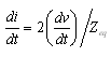
 : rate of rise of voltage surgeD: maximum allowable separation distance between junction J and PPF terminal.
 : Basic Lightning Surge Insulation Level of the PPF
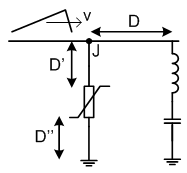 | Figure 6. Distance of arrester from PPF and earth |
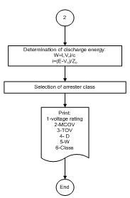
Step6: The discharge energy is calculated as follows:When metal-oxide arresters are energized, it will absorb energy that results in a temperature increase of its elements. If the temperatures of the elements reach a high enough level, damage to the valve elements can occur, leading to an electrical breakdown and failure of the arrester. The energy that an arrester can absorb during an overvoltage event without impairing the arrester’s ability to serve the intended function following the event is usually called “energy handling capability” or “energy withstands capability.” This capability is often expressed in terms of kilojoules per kV of arrester MCOV or per kV of duty-cycle rating[2].The amount of energy is proportional to surge magnitude, wave shape, the system impedance, circuit topology, the arrester voltage-current characteristics, and the number of operations (single/multiple events). The energy which is discharged by an arrester, W, in joule, may be conservatively estimated by[2]: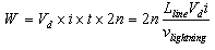 | (20) |
The equation (20) assumes that the entire line is charged to a surge voltage (which exists at the arrester location) and is discharged through the arrester during n propagation and reflection. n is supposed 10 in common. The discharge voltage and current are related by the equation (21):  | (21) |
Finally, considering the application guides of the manufacturer, and calculated W, thermal class of arrester is determined.Figure(7) shows the steps of the arrester selection under harmonic conditions.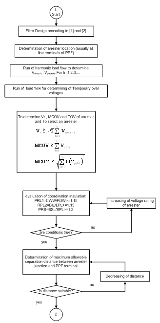 | Figure 7. Flowchart of arrester selection in harmonic conditions |
 | Figure 8. Continuation of flowchart of arrester selection |
6. Case Study and Simulation
Figure(9) shows a simple system studied in this paper. The system may not be a very practical distribution system, but it is interesting from the point of view of arrester design in harmonic conditions. The simulation is carried out based on ATP software.Lightning protection must be designed for the worst case. Therefore, it is supposed that, the line is cut during lightning as shown in figure (9).The harmonic voltage spectrum in the terms of the fundamental in the PPFs bus is according to table(II).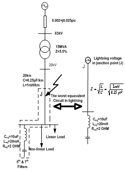 | Figure 9. A simple system for investigation of PPFs under lightning surge condition |
| Table 2. Harmonic spectrum of 6-pulse load |
| | h | 5 | 7 | 11 | 13 | 17 | 19 | 23 | 25 | 29 | 31 | | % | 0.5 | 0.4 | 2.5 | 1.8 | 1.5 | 1.1 | 0.8 | 0.4 | 0.3 | 0.1 |
|
|
Table(II) terminates at the 31st harmonic. The other parameters for simulation are supposed: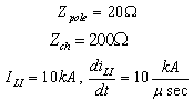 | (22) |
Considering table(II), Va-peak and MCOV are calculated as follows: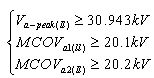 | (23) |
Therefore MCOV=20.2kV
6.1. Simulation Result without the Arrester
From equation (22), it can be written: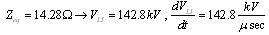 | (24) |
The wave shape of the lightning voltage is designated by a combination of two numbers. At the first, an index of the wave front, is the virtual duration of the wave front in microseconds (Tf). At the second, an index of the wave tail, is the time in microseconds (Ttail). In this paper, they are supposed as: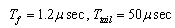 Figure(10) shows the voltage wave shape at the terminals of the PPFs. Curve(1) denotes the lightning voltage and curve(2) shows the voltage at the terminals of the PPFs where lightning discharge occurs at point placed 20km from the PPFs. As shown, the voltage peak of the PPFs reaches two times the peak value of the lightning voltage. The peak of curve (2) decreases because of resistive losses of the inductors employed in the PPF.
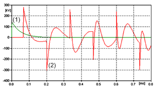 | Figure 10. The lightning voltage and the voltage at the terminals of the PPFs, without arrester |
Reflected voltages of the lightning surge are shown in the figure(10). The primary delay of the voltage of the PPFs is 66µsec because of the travelling time. From figure (10), the voltage peak of the PPFs is around 280kV and the PPFs cannot withstand it. Therefore, if the PPFs are not protected against lightning surges, they will be damaged certainly.
6.2. Simulation result with arrester
An arrester (Vrated=24kV, MCOV=19kV) is selected which its V-I characteristic is shown in table (III).| Table 3. V-I characteristic of the arrester |
| | V(kV) | 50 | 52 | 59 | 64 | 72 | | I(kA) | 0.5 | 1 | 5 | 10 | 20 |
|
|
Where , the V-I characteristic of the surge arrester can be estimated:
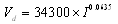 | (25) |
From equation (21), the electrical system curve can be written as: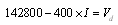 | (26) |
Solving above equations, discharging voltage (Vd) and discharging current (I) of arrester are calculated 48.5kV and 240A respectively. Figure (11) shows the curves of the surge arrester and the electrical system. As shown in the figure, the intersection point of the curves is at (240A, 48.5kV).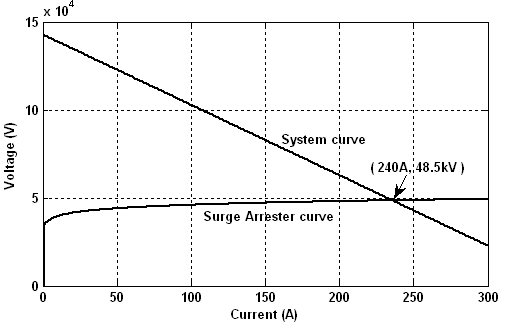 | Figure 11. The curves of the arrester and the electrical system |
Figure (12) shows the voltage at the terminal of the PPFs with arrester. As shown in figure (12), the chopped voltage at terminal of the PPFs is around 48kV. Therefore, the simulation and the calculation results confirm together. As shown in the figure, the arrester protects the PPFs perfectly.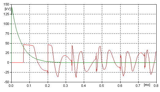 | Figure 12. The lightning voltage and the voltage at the terminals of |
7. Conclusions
In this paper, an algorithm for consideration of arrester selection is presented where harmonic voltages may be significant. The presented selection method consists of the harmonic condition and occurrence of the lightning surges at the terminals of the PPFs. The analysis of the PPFs under harmonic conditions with and without metal-oxide arrester protection has been studied in this paper. Two cases are studied, and it is seen that the presented method is effective to protect the PPFs in allowable limitation.
References
| [1] | J. C. Das, ‘’ Passive Filters—Potentialities and Limitations ’’, IEEE Transactions on Industry Applications, vol. 40, no. 1, Jan./Feb. 2004, pp. 187 - 197 |
| [2] | Surge Protective Devices Committee,'' IEEE Guide for the Application of Metal-Oxide Surge Arresters for Alternating-Current Systems'', IEEE Std C62.22-1997 |
| [3] | Premila Manoha, H.S. chandrasekhamiah,'' Application of ZnO Varistor Protection To Capacitors of Artificially Commutated Inverter in HVDC System'', IEEE Transactions on Power Systems, Vo1.6, No.1. Feb. 1991, pp. 356 - 363 |
| [4] | Marcus O.Durham, Robert A. Durham, Karen D. Durham,'' Transient Voltage Surge Suppression Design And Correlation'', In Proc. Of 47th Annual Petroleum and Chemical Industry Conference, 11-13 Sep. 2000, pp. 207 - 215 |
| [5] | John E. Harder,'' AC Filter Arrester Application'', IEEE Transactions on Power Delivery, Vol. 11, No. 3, July 1996, pp. 1355 – 1360 |
| [6] | K. Munukutla, V.Vittal, G.T Heydt, D.Chipman, B Keel, '' A Practical Evaluation of Surge Arrester Placement for Transmission Line Lightning Protection'', IEEE Transactions on Power Delivery, No. 25 , Issue: 3 , pp. 1742 – 1748 |
| [7] | M.K. Zadeh, H. Abniki, A.A.S Akmal,'' The modeling of metal-oxide surge arrester applied to improve surge protection'', In Proc. of 2nd International Conference on Power Electronics and Intelligent Transportation System (PEITS), 19-20 Dec. 2009 ,pp. 238 – 243 |
| [8] | Yoshihide Hasa,'' Handbook Of Power System Engineering'', 2007, John Wiley and Sons Ltd. |
| [9] | Transmission & Distribution Committee,'' IEEE Guide for Application and Specification of Harmonic Filters'', IEEE Std 1531-2003 |
 Abstract
 Reference
 Full-Text PDF
 Full-Text HTML