Marija Mirošević 1, Zlatko Maljković 2
1Department of Electrical Engineering and Computing, University of Dubrovnik, 20000 Dubrovnik, Croatia
2Faculty of Electrical Engineering and Computing, University of Zagreb, 10000 Zagreb, Croatia
Correspondence to: Marija Mirošević , Department of Electrical Engineering and Computing, University of Dubrovnik, 20000 Dubrovnik, Croatia.
| Email: |  |
Copyright © 2012 Scientific & Academic Publishing. All Rights Reserved.
Abstract
The aim of this paper is to analyze the dynamics of generator units during sudden impact load, direct-on-line starting loaded induction motors connected to a synchronous generator in autonomous operation. A complex mathematical model of isolated electrical grid consisting of: diesel engine, synchronous generator and motor drives have been developed. In the previous works, most often in case of direct starting of the induction motor to the grid, the torsional dynamics of the unit was not analyzed consistently, but rather the whole generator-unit was considered as a single rotating mass. Here, system with two rotating masses, one at the side of the diesel engine and the other at the side of the synchronous generator is analyzed. Ship electrical grids have such units with a diesel engine and a synchronous generator as sources. Connection of bigger induction motors to the ship's grid with such sources is the most difficult transition regime for units due to electricity loads and also due to the torsional strains in the shaft lines. This paper attempts to analyze the torsional dynamics, combining thus the knowledge in this field with the knowledge of motor drives with induction motors. The dynamics of generator-units, as well as induction motors during direct-on-line starting on isolated electrical grid is analyzed.
Keywords:
Diesel Generator-Unit, Air-Gap Torque, Torsional Torque, Torsional Oscillation, Induction Motor Starting
1. Introduction
Dynamics of generator set is interesting in isolated electrical networks, such as the ship electrical grid or backup supplies, where the main source of electricity is synchronous generator coupled to a prime mover - diesel engine. The synchronous generator, usually of salient-pole machine, is equipped with an automatic voltage controller for purposes of voltage maintaining. The speed of diesel engine is maintained using a speed governor. In many applications the diesel generator can suffer significant impacts loads that can produce disturbances in the isolated network. It can be expected that diesel generator units change operation from unloaded to full load condition in a single step load application. These changes cause a change in voltage and frequency, which in turn affects the quality of electric power systems. Induction motors are the most common active loads as they are used for water pumps, compressors, winches and other applications that may provide either continuous or intermittent operations, so, there are a number of induction motors connected in the same bus. In many applications induction motors are direct-on-line switch-started and they draw high starting currents, several times the full load current. This current causes a significant voltage dip on the isolated electrical grid. The voltage drop will cause disturbances in the torque of any other motor running on the isolated electrical grid. Increasing the load, such as a sudden change load, significant disturbances in the system appeared and the situation is particularly difficult because of relatively strong electrical coupling between electrical grid and loads. To study the dynamics and transient performance of such a system, the group of three motors is selected.Torsional dynamics of generator units is interesting in the case of large turbine generator units[1], thus, the working group of the Study Committee for Rotating Electrical Machines of the CIGRE Association has developed a benchmark model for calculating torsional stresses of the turbine generator shaft and the shaft fatigue[2]. The influence of the machine parameters and disturbances on torsional stresses is analyzed in many papers[3]-[6].However, in smaller, isolated electric power systems it is interesting to analyze the torsional dynamics of a unit with a diesel engine (DM) and a synchronous generator (SG). In such electrical networks, such as marine and offshore power systems, the connection of bigger induction motors is the most severe form of impact load in terms of electrical load and stresses due to torsion, particularly in cases where motors, during run-up period, are loaded. Therefore, it is interesting to analyze the torsional dynamics of a unit with a diesel engine and a synchronous generator.In the previous works, in the case of a direct connection of an induction motor, the torsional dynamics of the unit was not analyzed consistently, because the whole generator unit was considered as a single rotating mass. In this paper, diesel generator units is modeled as a system with two rotating masses, one at the side of the diesel engine and the other at the side of the synchronous generator. Masses are connected one to another by a flexible coupling. The flexible connection at the joint allows, in transient, these masses to rotate at a different speed. The relative angle shifts occur between these masses, allowing thus the analysis of the torsional dynamics in the coupling.
2. Model of Isolated Electrical Grid
To analyze the influence of impact load on torsional dynamics of generator units at impact load direct-on-line starting loaded induction motors a complex mathematical model is developed. The mathematical model involves: a diesel engine, a three phase synchronous generator, their mechanical coupling, non-regulated induction motors fed directly from the synchronous generator terminals.As usually, electrical machines are simulated with either fluxes or currents as state variables. Choosing fluxes as the state variables the equations are less complicated. Here, in the transient dq-axis model of a synchronous generator, as well as in induction motors model, all winding currents are selected as state variables. Thus later from the current equations the fluxes as well as air-gap torque are obtained. The basis of the mathematical model is set of differential equations of the synchronous generator in the standard dq-axis form. The model of a synchronous generator is given in rotor reference frame (ω is rotor electrical speed) with following set of voltage equations: 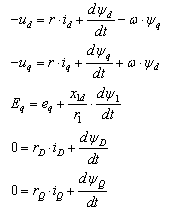 | (1) |
where u, i, r, and Ψ denote voltage, current, resistance and flux respectively.The synchronous generator is presented as a machine with three armature windings, field winding placed in the rotor and damper windings. One damper winding is located along direct-axis (D), and one along the quadrature-axis (Q). The voltage equations are written in generator (source) convention system, in which synchronous machines are usually represented[7] and[8].Equations of excitation are written in motor (load) convention system. The voltage controller is modelled as PI and is implemented on the model. The air-gap torque of the synchronous generator is as follows: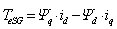 | (2) |
The role of the induction motor and its parameters, as an active consumer in transient, was analyzed in[9]. The fifth order model of the squirrel-cage induction motor is used to analyze the influence of impact load on torsional dynamics of generator units during direct on line starting of induction motors. The machines are presented in the dq-axsis form, the synchronously rotating reference frame. The standard modeling approach, which can be found in detail in[8], is implemented.In the transient dq axis model of induction motor, as mentioned before, all winding currents are selected as state variables, so stator voltage equations are: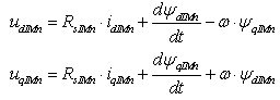 | (3) |
where idIMn and iqIMn denote components in d and q axis of stator current, while ΨdIMn and ΨaIMn represent the dq components of the stator flux linkage: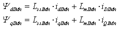 | (4) |
The rotor voltage equations are: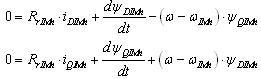 | (5) |
where iDIMn and iQIMn denote components in d and q axis of stator current. The equations that represent d-q components of the rotor flux linkage: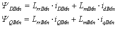 | (6) |
However, three loaded induction motors are involved in the model and index n is one for the first, two for the second, and three for the third motor. As one can differentiate variables of induction motor and synchronous generator index IMn is used in (3) to (8).The voltage equations set is completed with an equation of rotational mass motion: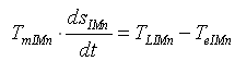 | (7) |
where: TLn represents load torque on the motor's shaft, while TeIMn denote air-gap torque of the induction motor: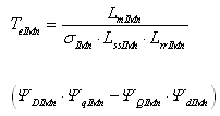 | (8) |
In order to analyze the influence of impact load on torsional dynamics of generator units it is necessary to model diesel engine and its dynamic behavior. To simulate the complete dynamics of a diesel engine system, a very large order model will be required. It is necessary to set up a system of differential equations which includes an equation of the engine, the turbocharger, the air collector, the exhaust system, and the speed controller. Taking into account the differential equations for the turbocharger and the exhaust system, according to[10] and[11], requires the knowledge of a number of characteristics of diesel engines that require complex experimental measurements. However for most studies on speed dynamics of internal combustion engines, it is sufficient to use a lower order model. Similar approaches where adopted in diesel engine simulation studies. The studies carried out in[12] showed that the mentioned omissions do not affect significantly the results and that the proportionality of torque to the amount of injected fuel can be assumed. This simplification is allowed when it is of interest to observe the transitional process of a synchronous generator. Accordingly, the dynamic behavior of diesel engine and speed controller can be described by the following system of equations: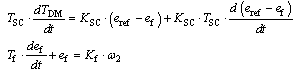 | (9) |
The influence of machine parameters and the torsional stress disturbance are analyzed in many papers[3],[4],[5-6], here, the torsional dynamics of isolated electricity networks is interesting. Mechanical coupling of a diesel engine and a synchronous generator is considered to be a rotating system with two concentrated masses, the mass of generator rotor and rotating mass of diesel engine. Flexible coupling connects these two rotating shafts, as one can see in Figure 1. This coupling allows masses to rotate at a different speed in transients.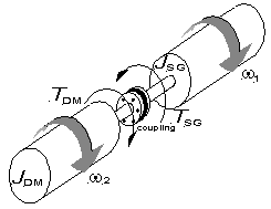 | Figure 1. Sketch of mechanical system under study |
 | Figure 2. Block diagram of integral motor drives |
Thus, the equations of motion of a generator (ω1) and diesel engine (ω2) respectively are: 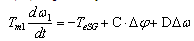 | (10) |
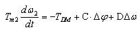 | (11) |
where: 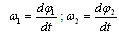 | (12) |
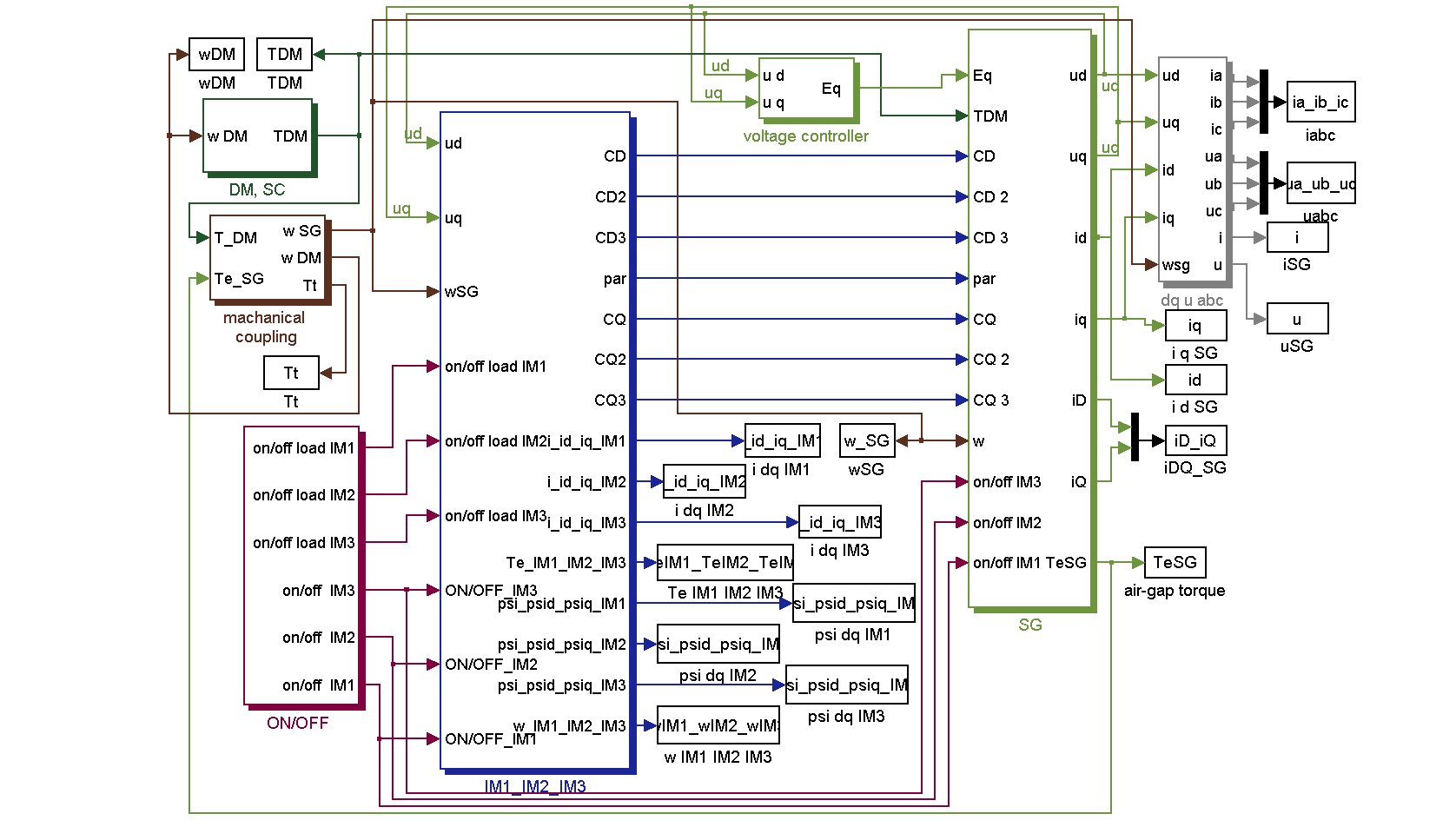
ω1, ω2 are angular velocity of the generator rotor and prime mover respectively,Δφ, Δω represents twist angle difference and the angular velocity difference, respectively. The generator’s equation of motion involves electrical torque TeSG, whereas TDM represents prime mover torque. Mechanical torque of the diesel engine, C – torsional stiffness, D – is the coefficient of internal damping. This allows calculating torque at coupling zone[13].The analysis of the dynamics of the generator unit at impact load, i.e. direct-on-line starting of the induction motors was performed by the application of the software package Matlab/Simulink. The block diagram of integral motor drives is presented in Figure 2 and it consists of subsystems: DM, SC - diesel engine, speed controller, SG – three phase synchronous generator, mechanical coupling between them, voltage controller, and IM1_IM2_IM3 - subsystem in which three induction motors are modeled. Induction motors are fed directly from the synchronous generator terminals and the moment of connecting to the grid is controlled by ON/OFF subsystem. This subsystem is also used for switching the load on the motor shaft.The validity of the mathematical model of the generator-unit at impact load direct-on-line starting of non-loaded induction motor was checked in the previous work[14] by comparing the results of the simulation and the measurement on the generator-unit with a diesel engine of 46.4 kW and a synchronous generator of 40 kVA, to which a motor drive of 7.5 kW was connected. The results obtained by numerical calculation indicate that, compared to the results of the measurements on an actual ship drive with induction motor, the set mathematical model can be applied with sufficient certainty.
3. Study Cases and Computation Results
The aim of this paper is to analyze the torsional dynamics of generator units during sudden impact load, direct-on-line starting loaded induction motors connected to a synchronous generator in autonomous operation. The synchronous generator is initially in a steady state unloaded condition operating at the rated voltage (1 p.u.) and stator currents being zero. In this condition rotation speed of the diesel engine (ωDM) is equal to the speed of the generator (ωSG), however, the rated speed is 1 p.u.At the chosen moment the first, loaded induction motor (IM1) is connected directly to the terminals of the synchronous generator. Later, when the first motor has run-up successfully, the second (IM2) and third (IM3) loaded induction motors are connected to the loaded synchronous generator. Two cases are considered.In the first case, motors are started with a constant load TlIM1=TlIM2=TlIM3=0.1 p.u. on motor shaft. The second, induction motor is connected after the first on has run-up successfully. In the second case, the first induction motor run up loaded with TlIM1=0.1 p.u., while double load on the second and third induction motor shaft is applied (TlIM2=TlIM3=0.2 p.u.). Additional load of TlIM1*=0.1 p.u., on the first loaded induction motor shaft is applied, in both cases, at the beginning of the start-up period of the third induction motor.When the supply has just been switched on the induction motor, the load on the generator-unit is instantaneously increased. Thus, the initial part of transients is defined in the initial (sub-transient) phase of the transitional phenomenon by locked-rotor torque of the induction motor. The second, induction motor is connected after the first on has run-up successfully. At the beginning of the start-up period of the third induction motor additional load of 0.1 p.u. occurs on the IM1 shaft, approximately 0.1s after IM3 run began. Speed transient of the induction motors during start-up period are presented in Figure 3. 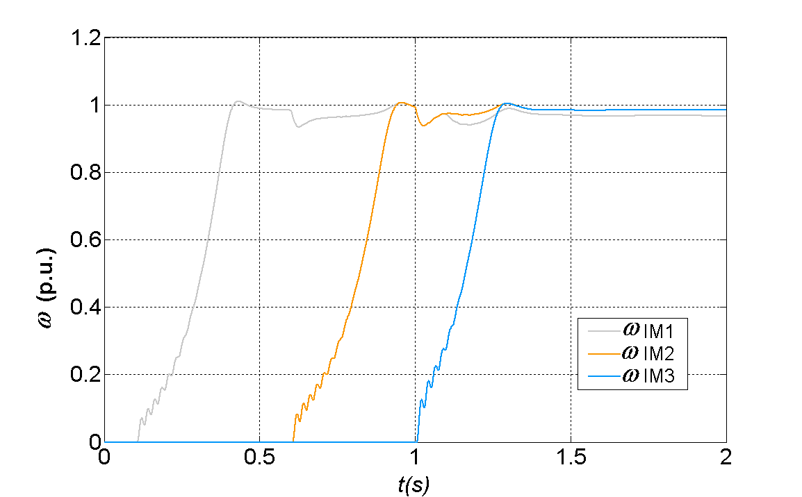 | Figure 3. Speed transient of the induction motors (ωIM1, ωIM2, ωIM3) during start-up period of IM1, IM2 and IM3. The load on IM shaft TlIM1=TlIM2=TlIM3=0.1 p.u., TlIM1*=0.1 p.u |
 | Figure 4. Transient of the air-gap torque of the synchronous generator (TeSG) during start-up period of IM1, IM2 and IM3. The load on IM shaft TlIM1=TlIM2=TlIM3=0.1 p.u., TlIM1*=0.1 p.u |
Connecting motors to the grid the load on the generator increases and the air gap torque of synchronous generator is growing up. At the instant of starting of the first induction motor, the air-gap torque of the synchronous generator momentarily reaches maximum value of 1.2 p.u. and below, as one can see in Figure 4, oscillates about an average positive value. Changes in the air-gap torque of the synchronous generator TeSG can be noticed during the whole start-up period of induction motors. Changes in the air-gap torque of the synchronous generator TeSG can be noticed during the whole start-up period of induction motors (Figure 3). These results in the difference of the torque angle between the generator rotor and the diesel engine shaft due to the definite final stiffness of the shaft and different inertia of generator and diesel engine, however, torque in the coupling Tt is presented in Figure 5. 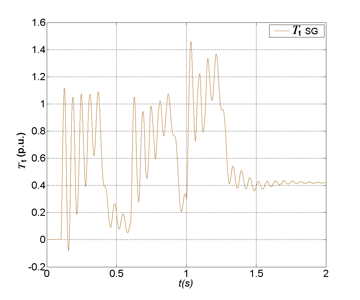 | Figure 5. Transient of torsional torque (Tt), during start-up period of IM1, IM2 and IM3. The load on IM shaft TlIM1=TlIM2=TlIM3=0.1 p.u., TlIM1*=0.1 p.u |
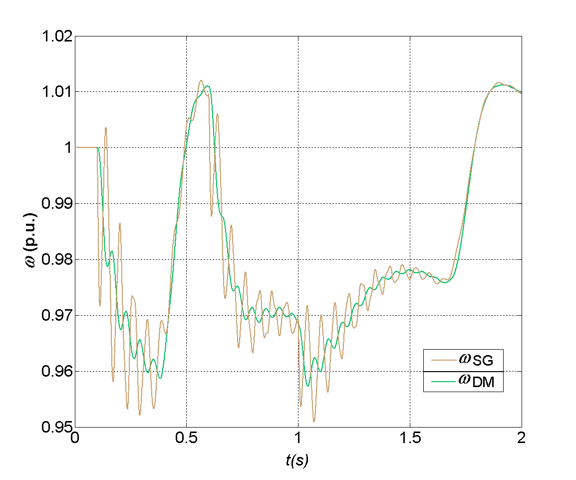
Torsional oscillations are induced with first magnitude of 1.12 p.u. at the beginning of the start-up period of IM1. At the time of the starting of IM3 magnitude achieves a max. value of 1.46 p.u.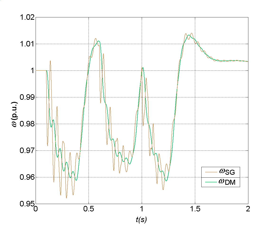 | Figure 6. Speed transient of synchronous generator (ωSG) and diesel engine (ωDM) during start-up period of IM1, IM2 and IM3. The load on IM shaft TlIM1=TlIM2=TlIM3=0.1 p.u., TlIM1*=0.1 p.u |
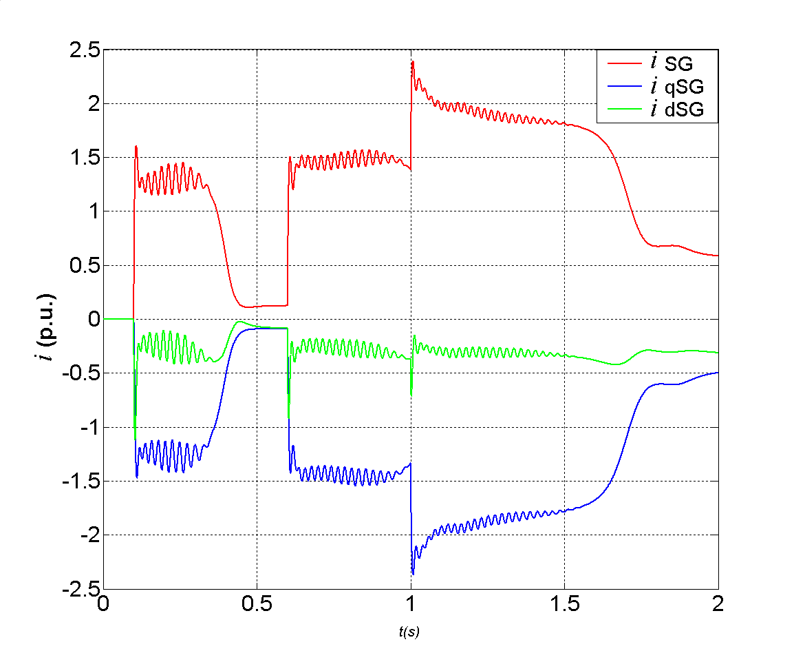
When induction motor is connected to an idle diesel-generator the prime mover decelerating. The speed governor responds to changes in load and fuel supply is growing, so the torque on the motor shaft increasing. Speed transient of synchronous generator and diesel engine are presented in Figure 6. The response from the rotation speed of the synchronous generator indicates torsional oscillations which are dampened already after several oscillations.Increases in the synchronous generator’s load, during acceleration period of induction motors, the high starting currents are appeared. Thus transients of synchronous generator stator current and components in d and q axis are presented in Figure 7. 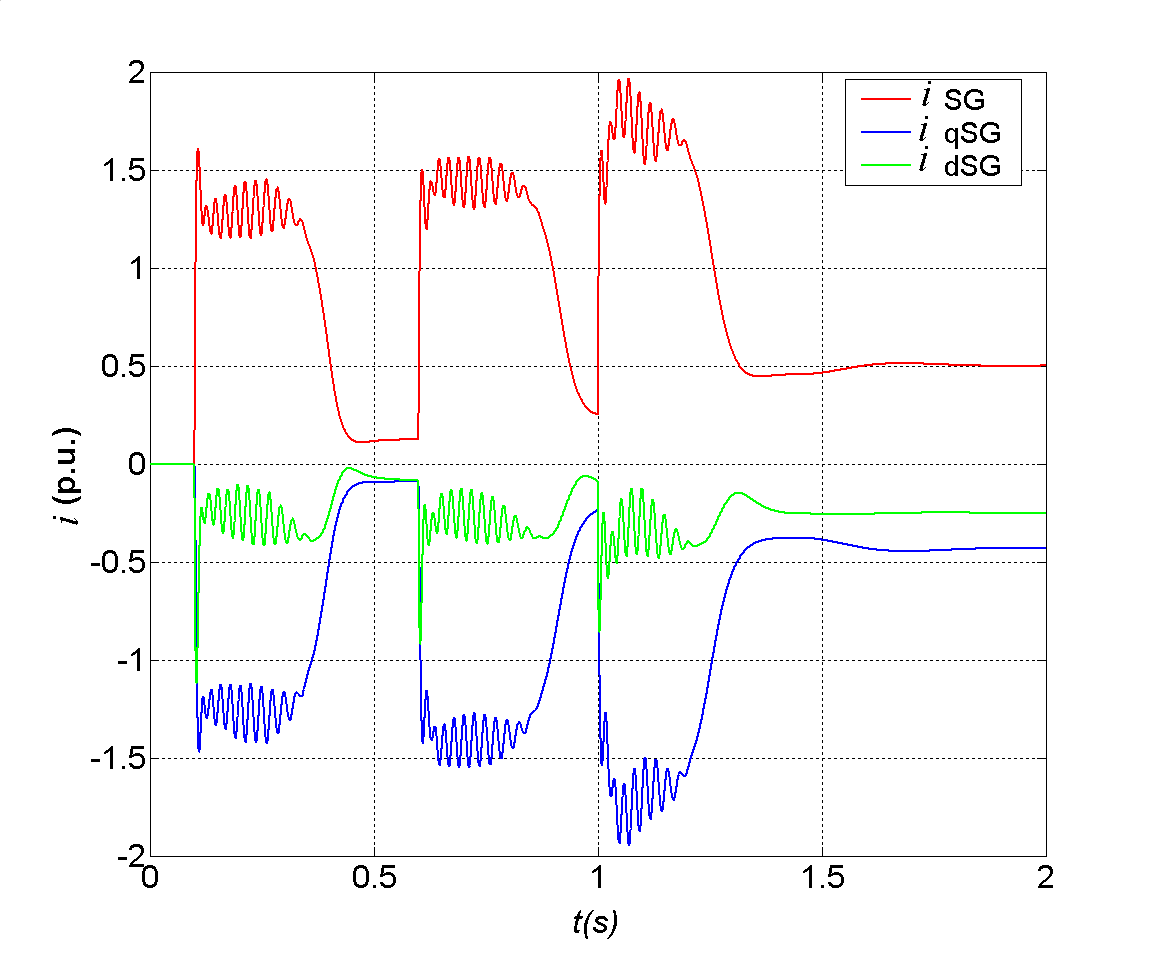 | Figure 7. Transients of: stator current of the synchronous generator (iSG), components in d (idSG) and q (iqSG) axis, during start-up period of IM1, IM2 and IM3. The load on IM shaft TlIM1=TlIM2=TlIM3=0.1 p.u., TlIM1*=0.1 p.u |
The inrush current of the first induction motor, at the instant of starting, as one can see in Figure 8, reaches the magnitude of the first oscillation of 1.73 p.u. At the instant when the third induction motor is connected to the grid, the magnitude of the first oscillation momentarily reaches 2.2 p.u. 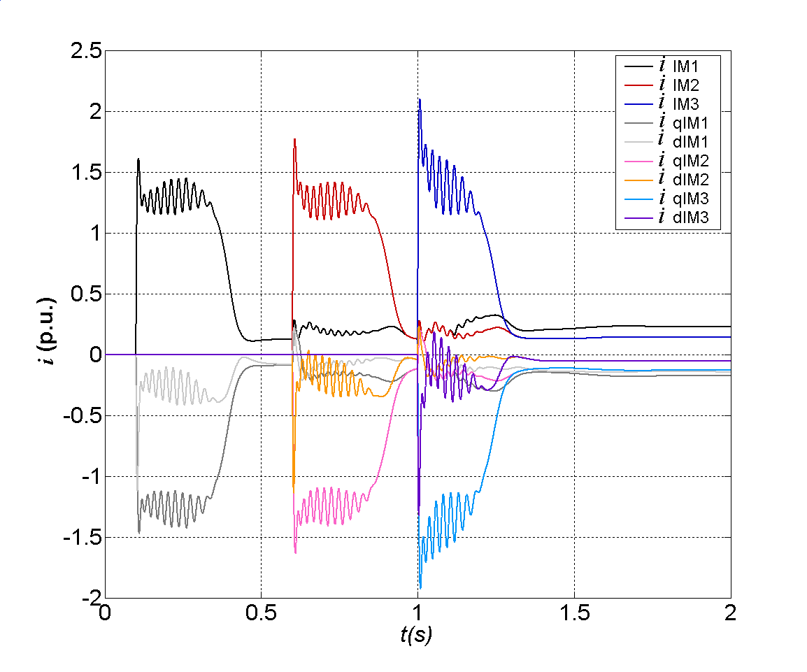 | Figure 8. Transients of: stator currents of induction motors (ilIM1, ilIM2, ilIM3), components in d (idlIM1, idlIM2, idlIM3) and q (iqlIM1, iqlIM2, iqlIM3) axis, during start-up period of IM1, IM2 and IM3. The load on IM shaft TlIM1=TlIM2=TlIM3=0.1 p.u., TlIM1*=0.1 p.u |
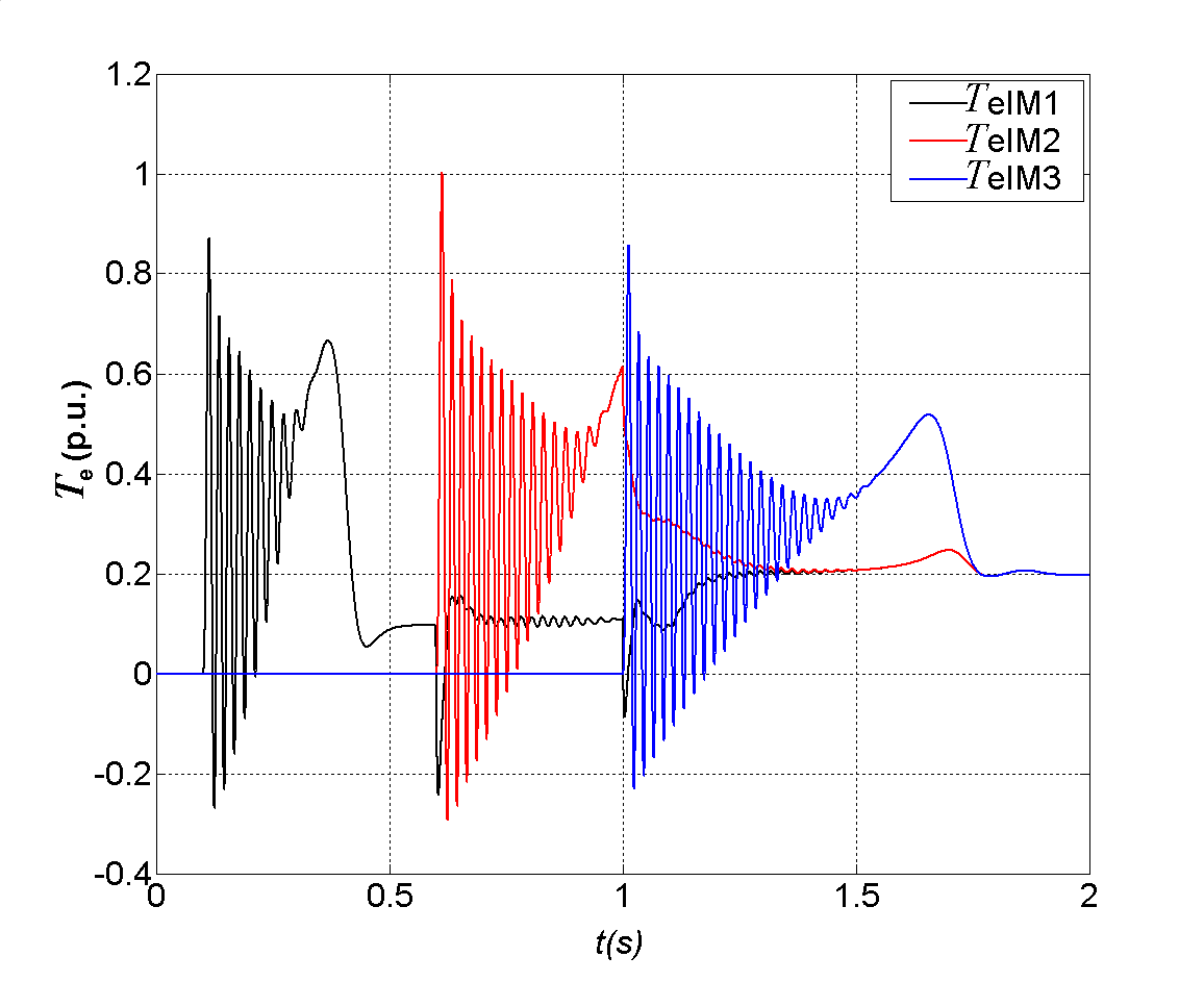
The air-gap torque of induction motors are presented in Figure 8. At the instant of starting, the air-gap torque of the first induction motor momentarily reaches 0.87 p.u. First magnitude of 1 p.u. is appeared in transient of the air-gap torque of the second motor. At the moment of starting the third induction motor TeIM3 momentarily achieves 1.39 p.u. as one can see in Figure 9.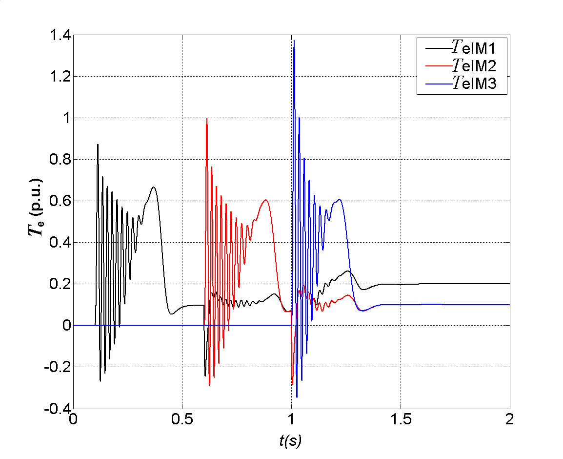 | Figure 9. Transient of: air-gap torque of induction motors (TeIM1, TeIM2, TeIM3), during start-up period of IM1, IM2 and IM3, during start-up period of IM1, IM2 and IM3. The load on IM shaft TlIM1=TlIM2=TlIM3=0.1 p.u., TlIM1*=0.1 p.u |
Corresponding stator flux linkage of induction motors, during direct-on-line starting are presented in Figure 10.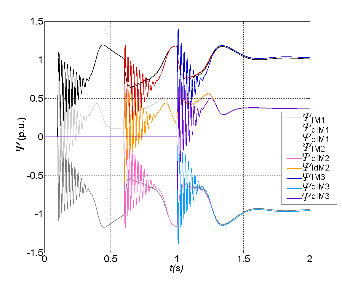 | Figure 10. Transients of: stator flux linkages of induction motors (ΨIM1, ΨIM2, ΨIM3) and their components in d (ΨdIM1, ΨdIM2, ΨdIM3) and q (ΨqIM1, ΨqIM2, ΨqIM3) axis during start-up period of IM1, IM2 and IM3. The load on IM shaft TlIM1=TlIM2=TlIM3=0.1 p.u., TlIM1*=0.1 p.u |
Most induction motors on board ship are direct-on-line switch-started and they cause a significant disturbance in transients, especially if the load torque on the motor shaft is increased and also depending on the time of the starting of each motor. It is a particularly difficult situation because of relatively strong electrical coupling between generator and loads as well as torsional strains in the shaft line.In order to get a better insight into the dynamics of drives, in the second case the induction motors IM2 and IM3 are loaded with double load on the shaft, thus TlIM2=TlIM3=0.2 p.u. In the first case, next induction motor is started after the previous one ran-up successfully.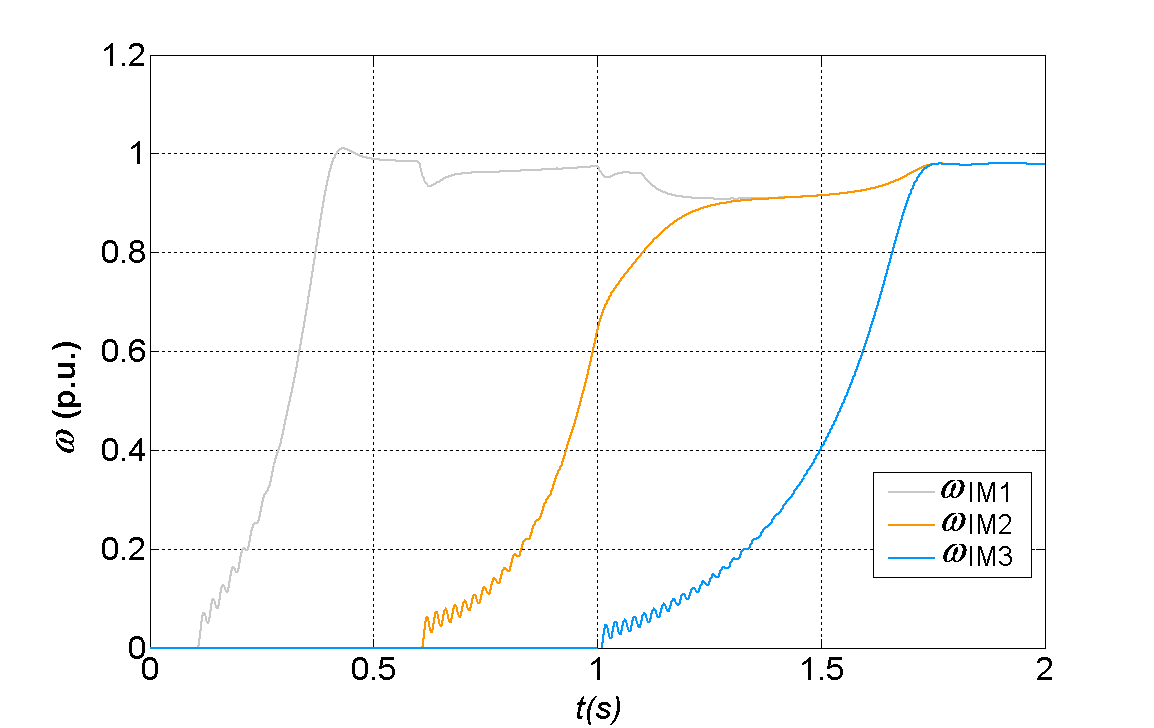 | Figure 11. Speed transient of the induction motors (ωIM1, ωIM2, ωIM3) during start-up period of IM1, IM2 and IM3. The load on IM shaft TlIM1=0.1 TlIM2=TlIM3=0.2 p.u., TlIM1*=0.1 p.u |
In the second case, as one can see in Figure 11, the acceleration time of the second induction motor is longer, thus the third induction motor is connecting to the supply during the start up period of the second one (IM2). At the beginning of the start-up period of the third induction motor the impact load of additional T*lIM1=0.1 p.u. on the first loaded induction motor shaft is applied. In that moment the run-up of second induction motor is not finished yet.Torsional oscillations are induced with first magnitude of 1.1 p.u. at the beginning of the start-up period of IM1, as in previous case, because the load on the first induction motor shaft is not changed yet. The transient of torsional torque of the second induction motor oscillations are longer present, the start-up period of the second induction motor is longer, because of decreasing load on the motor shaft. At the beginning of the start up period the induction motor accelerating, the speed is growing up. Connecting the third induction motor to the grid, acceleration of the second one is slowed, and further decreases when the additional load is connected to the first induction motor shaft. At the moment of connection the third induction motor to the grid, the motor is double loaded now, magnitude reaches higher value 1.46 p.u. Torsional oscillations are longer present than in the first case and damped at the end of the start-up period of the third induction motor, as one can see in Figure 12. The oscillations are present in speed transients of the synchronous generator (ωSG) as well as in diesel engine (ωDM). In the first case, the speed of synchronous generator, as well as diesel engine speed increase after the first and second induction motor run – up successfully. In the second case, when the third induction motor is connecting to the grid, the run-up of the second induction motor is not finished, so the speed of synchronous generator continue decreases and approaches to value of 0.95 p.u. (Figure 13).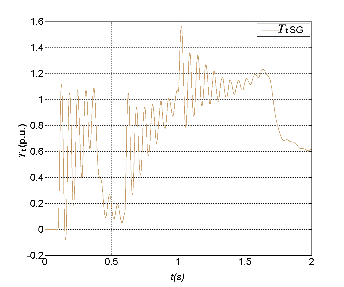 | Figure 12. Transient of torsional torque (Tt), during start-up period of IM1, IM2 and IM3. The load on IM shaft TlIM1=0.1 TlIM2=TlIM3=0.2 p.u., TlIM1*=0.1 p.u |
 | Figure 13. Speed transient of synchronous generator (ωSG) and diesel engine (ωDM) during start-up period of IM1, IM2 and IM3. The load on IM shaft TlIM1=0.1 TlIM2=TlIM3=0.2 p.u., TlIM1*=0.1 p.u |
Connecting motors to the grid the load on the unit increases, the air gap torque of synchronous generator is growing up and during the transient electromagnetic torque of the synchronous generator approaches the value of 1.8 p.u. Changes in the air-gap torque of the synchronous generator TeSG can be noticed during the whole start-up period of induction motors (Figure 14).Oscillations that occurred during start-up periods in air gap torque of induction motors are longer presented in the second case. Changes in electromagnetic torque of the first and the second induction motors occurred because of interaction between generator and loads. The air gap torque of induction motors during run-up period is presented in Figure 15. 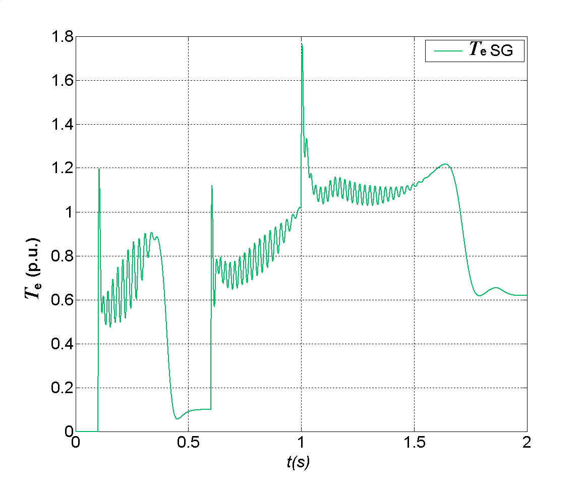 | Figure 14. Transient of the air-gap torque of the synchronous generator (TeSG) during start-up period of IM1, IM2 and IM3. The load on IM shaft TlIM1=0.1 TlIM2=TlIM3=0.2 p.u., TlIM1*=0.1 p.u |
 | Figure 15. Transient of: air-gap torque of induction motors (TeIM1, TeIM2, TeIM3), during start-up period of IM1, IM2 and IM3, during start-up period of IM1, IM2 and IM3. The load on IM shaft TlIM1=0.1 TlIM2=TlIM3=0.2 p.u., TlIM1*=0.1 p.u |
Current of the synchronous generator is increased by increasing the load. The oscillations are present in transient of stator current, as one can see in Figure 16 and Figure 17, during whole start-up period oscillating about higher average value than in previous case, and damped at the end of start-up period, as presented in Figure 17. Transients of stator current of induction motors and their components in d and q axis, during start-up period of IM1, IM2 are presented in Figure 16. One can see that connection of a next induction motor to the grid causes changes in transients of all induction motors which are already connected to the synchronous generator. 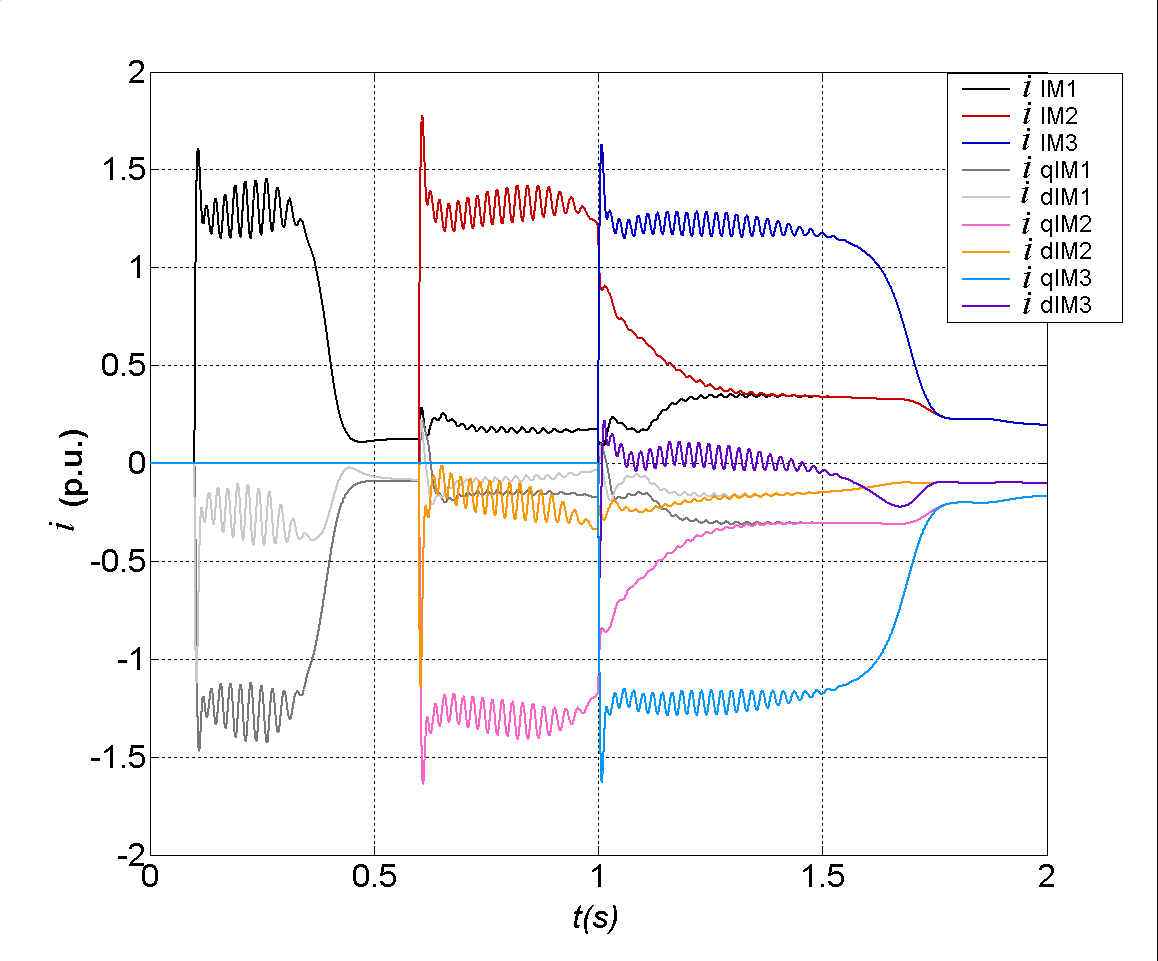 | Figure 16. Transients of: stator current of the synchronous generator (iSG), components in d (idSG) and q (iqSG) axis, during start-up period of IM1, IM2 and IM3. The load on IM shaft TlIM1=TlIM2=TlIM3=0.1 p.u., TlIM1*=0.1 p.u |
 | Figure 17. Transients of: stator current of induction motors (iIM1, iIM2, iIM3), and their components in d (idIM1, idIM2, idIM3) and q (iqIM1, iqIM2, iqIM3) axis, during start-up period of IM1, IM2. The load on IM shaft TlIM1=0.1 TlIM2=TlIM3=0.2 p.u., TlIM1*=0.1 p.u |
Corresponding stator flux linkage of induction motors, in the second case are presented in Figure 18.Disturbances, which arise in the system during sudden impact load on isolated electrical grid, influence both, electrical and mechanical characteristics of diesel generator units. The mechanical system of prime mover and synchronous generator is modeled as a system with two rotating masses, one at the side of the diesel engine and the other at the side of the synchronous generator, thus in transient these masses rotate at a different speed. The relative angle shifts that occur between these masses, allows the analysis of the torsional dynamics in the coupling. Connecting induction motor to the grid the torsional torque momentarily increasing and additionally growing up when connecting other motors to the grid. The current of synchronous generator (iabcSG), for the first case, when the load on induction motors shaft are: TlIM1=TlIM2=TlIM3=0.1 p.u., is presented in Figure 19. In Figure 20 generator current for the second case is presented. This is the total current that motors draw from the electrical grid.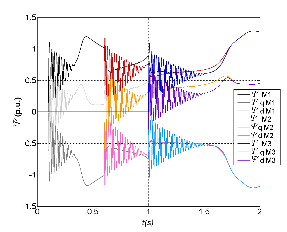 | Figure 18. Transients of: stator flux linkages of induction motors (ΨIM1, ΨIM2, ΨIM3) and their components in d (ΨdIM1, ΨdIM2, ΨdIM3) and q (ΨqIM1, ΨqIM2, ΨqIM3) axis during start-up period of IM1, IM2 and IM3. The load on IM shaft TlIM1=0.1 TlIM2=TlIM3=0.2 p.u., TlIM1*=0.1 p.u |
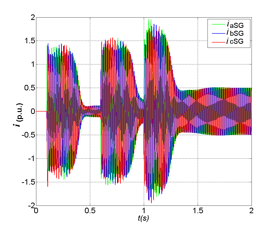 | Figure 19. Stator current (iabcSG) of the grid (synchronous generator), during start-up period of IM1, IM2 and IM3. The load on IM shaft TlIM1=TlIM2=TlIM3=0.1 p.u., TlIM1*=0.1 p.u |
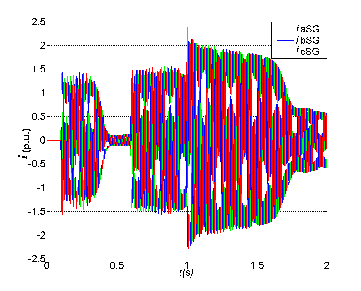 | Figure 20. Stator current (iabcSG) of the grid (synchronous generator), during start-up period of IM1, IM2 and IM3. The load on IM shaft TlIM1=0.1 TlIM2=TlIM3=0.2 p.u., TlIM1*=0.1 p.u |
4. Conclusions
Direct starting of induction motors in isolated electrical networks is the most difficult case of impact loads both in terms of electrical loads and stresses due to shaft torsion. Most induction motors on board ship are direct-on-line switch-started and they cause a significant disturbance in transients, especially if the load torque on the motor shaft is increased. Significant disturbance arises when, during the induction motor starting, there is a direct start of the second motor. It can be concluded that a significant torsional stress of the shaft is present for the cases of the starting of the second induction motor while the first motor starting is not yet finished. The developed mathematical model of integral motor drives together with the various operational cases allows the prediction of time responses of the characteristic variables in different operating conditions.
ACKNOWLEDGEMENTS
The presented results are carried out through the researches within scientific projects , New structures for hydrogenerating unit dynamic stability improvement“ and “Revitalization and operating of hydro generator” supported by Ministry of Science, Education and Sports in the Republic of Croatia.
References
| [1] | D. Lambrecht, T. S. Kulig, W. Berchtold, J. Hoorn, H. Fick, “Evaluation of torsional impact of accumulated failure combinations on turbine generator shafts as a basis of design guidelines”, CIGRE, Paris, 1984. Ref.11-06. |
| [2] | CIGRE SC 11, Working Group 11-01., “Problems of torsional stresses in the shaft lines of turbine generators, Part 1: Operating and experimental experience, Part 2: Benchmark model computation”, CIGRE, Paris, 1989. |
| [3] | V. Atarod, P. L. Dandeno, M. R. Iravani, “Impact of synchronous machine constants and models on the analysis of torsional dynamics”, IEEE Tran., vol. 7 n. 4, November 1992, pp.1456-1463. |
| [4] | M.R. Iravani, “A method for reducing transient torsional stress of turbine-generator shaft segments”, IEEE Trans. Power System, vol. 7 n. 1, 1992, pp. 20–27. |
| [5] | R. Hooshmand, M. Azimi, “Investigation of Dynamic Instability of Torsional Modes in Power System Compensated by SSSC and Fixed Capacitor”, International Review of Electrical Engineering, vol. 4 n. 1, February 2009, pp. 129-138. |
| [6] | M. H. Ali, T. Murata, J. Tamura, “Effect of Fuzzy Controlled Braking Resistor on Damping Turbine Generator Shaft Torsional Oscillations During Unsuccessful Reclosing”, International Review of Electrical Engineering, vol. 1 n. 5, 2006, pp. 711-718. |
| [7] | P. Vas, “Electrical Machines and Drives A Space vector theory Approach”, Oxford Science Publications |
| [8] | P. Krause, “Analysis of Electric Machinery”, McGraw-Hill, Inc. New York, N.Y. 1986. |
| [9] | Z. Maljković, M. Cettolo, M. Pavlica, “The Impact of the Induction Motor on Short-Circuit Current”, IEEE Industry Applications Magazine. 7 (2001), 4; 11-17. |
| [10] | V. I. Krutov “Dvigatelj vnutrennego sgorania kak reguliruemij object”, Mašinostroenie, Moskva 1978. |
| [11] | V. I. Tolšin, E. S. Kovalevskij, “Prethodnie procesi u dizel generatorov”, Mašinostroenie, Leningrad 1977. |
| [12] | V. Matijević, Z. Maljković, “Impact of speed regulation of diesel engines on the dynamic characteristics of synchronous generator”, Automatika, vol. 31, n. 3-4, 1990, pp. 141-150. |
| [13] | M. Mirošević, Z. Maljković, M. Milković, “The Influence of Impact Load on Torsional Dynamics of Generator Units”, EPE 21011, Proceedings of The 14th European Conference on Power Electronics and Applications, Birmingham, United Kingdom, T10, P1.-P6. |
| [14] | M. Mirošević, D. Sumina, N. Bulić, “Influence of Time Gap between Impact Loads on Torsional Dynamics of Generator Units“, “International Review of Electrical Engineering”, Vol. 5, No. 3, pp. 1012-1021, 2010. |
 Abstract
 Reference
 Full-Text PDF
 Full-Text HTML