-
Paper Information
- Next Paper
- Previous Paper
- Paper Submission
-
Journal Information
- About This Journal
- Editorial Board
- Current Issue
- Archive
- Author Guidelines
- Contact Us
Electrical and Electronic Engineering
p-ISSN: 2162-9455 e-ISSN: 2162-8459
2012; 2(3): 152-157
doi: 10.5923/j.eee.20120203.08
The Simulation, Design and Implementation of Bandpass Filters in Rectangular Waveguides
 Abstract
 Reference
 Full-Text PDF
 Full-Text HTML
Sarun Choocadee, Somsak Akatimagool
Department of Teaching Training in Electrical Engineering, Faculty of Technical Education, King Mongkut’s University of Technology North Bangkok, Thailand
Correspondence to: Somsak Akatimagool, Department of Teaching Training in Electrical Engineering, Faculty of Technical Education, King Mongkut’s University of Technology North Bangkok, Thailand.
| Email: |  |
Copyright © 2012 Scientific & Academic Publishing. All Rights Reserved.
This paper presents the simulation, design and implementation of bandpass filters in rectangular waveguides. The filters are simulated and designed by using a numerical analysis program based on the Wave Iterative Method (WIM) called WFD (Waveguide Filter Design) simulation. This simulation program can analyze the electrical network of filters. The sample waveguide filter is designed based on a proposed structure consisting of three circuits serving as a simple bandpass filter with two inductive irises and three inductive irises in a cascade. We determined that the operating frequency was equal to approximately 4.20-4.84 GHz. The waveguide filters were then implemented using an aluminum material. The analyzed results for the inductive iris obtained with the WFD program agree well with the results of CST Microwave Studio®. Finally, the measured results of sample waveguide filters are consistent with the simulation tool.
Keywords: Inductive Irises, Simulation Program, Bandpass Filter, Waveguide Filters Design, Wave Iterative Method
Article Outline
1. Introduction
- Presently, the development of technologies for wireless communications, particularly for use in the microwave frequency range, is critical to developing the economy and domestic industry and contributes to continued technology research and development. Microwaves filters were found to be necessary because a communication system can be used to separate the signals that would be needed for use. In several articles, researchers have studied the filters in waveguides, and the results of simulation programs are most interesting[1-4].The most popular waveguide filter is an iris filter[5-8]. The researchers cited on 3D simulators, such as CST Microwave Studio® and Advanced Design System (ADS), to design iris waveguide filters. The problems with the design of filters often include a lack of equipment and tools used to design and build them. Numerical methods related to electromagnetic waves have caused a revolution in microwave engineering; techniques such as FDTD (Finite Differential Time Domain)[1], Smoothed Piecewise Linear model (SPEL)[2], TLM (Transmission Line Matrix)[3], and the Moment method[4] have been developed. Each method has respective disadvantages and limitations for use in research and education. Some analysis methods for designing waveguide circuits are available in[1] to[8].Recently reported waveguide filter has several structures. Many accurate techniques have also been proposed but have complex algorithms[9-12]. The Ref.[9] explains a new method based on inverse scattering theory of single-mode planar waveguides in order to obtain a desired TE-mode profile. However, this method can also be expanded to analyze TM modes and for designing multi-mode planar waveguides. Also, an accurate CAD tool based on the merging the prototype synthesis and the structure extraction has been presented in[11] for the particular case of inline inductive waveguide filters.We observed that the most inductive iris in a waveguide has been designed with high accuracy through approximate modeling utilizing the full-wave analysis method. Therefore, the development and optimization of methods are necessary and important for an efficient electromagnetic waveguide analysis simulation tool.This paper proposes a simulation, design and implementation of bandpass filters by using the novel technique of Wave Iterative Method (WIM)[12], the CST Microwave Studio® and a network analyzer. The result can be used in microwave filter design for satellite communications and applied in education and in the telecommunication industry.
2. Numerical Analysis
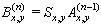
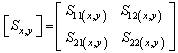
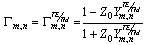
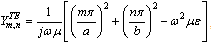
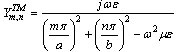
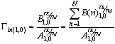
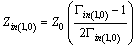
- An analysis of the electromagnetic wave properties within a waveguide consists of TE and TM field components. Most wave analyses will be calculated in the spectral domain based on the series integration equation to present the electromagnetic field and to analyze the two-port network parameters such that the result of the frequency response reflects the characteristic of various filter circuits. In this research, we will present the cooperation of waves between the spatial domain and the frequency domain.The calculating concept for electromagnetic wave propagation in a waveguide is based on the Wave Iterative Method (WIM). The operating process, shown in Figure 1, will present the amplitude and direction of the incident, reflected, and transmitted waves that propagate in the waveguide iris. On the iris, the waves are calculated in the spatial domain (Real) and the waves in free space are calculated in the frequency domain (Modes). To alternate between both domains, we use the Fast Fourier Transform (FFT) to reduce the computation time.
 | Figure 1. Wave Iterative Method in a rectangular waveguide |
 | (1) |
 | (2) |
 | (3) |
 | (4) |
 | (5) |
 | (6) |
 | (7) |
 | (8) |
 | (9) |
 | (10) |
 | (11) |
 | (12) |
 | (13) |
 | (14) |
3. WFD Simulation Results
- The simulation program conducts a numerical analysis using the Wave Iterative Method. This simulation program, called WFD (Waveguide Filter Design), consists of a main menu, parameter setup, and a design and display window, as shown in Figure 2. The WFD is constructed by using the GUI (Graphic User Interface) of MATLAB®. The user can set up the initial values that are used for calculating the two ports of the network, calculate the properties of the inductive iris and select the display windows of the simulated results. With the simulation program, it is possible to analyze and design a waveguide filter.
 | Figure 2. Waveguide Filter Design (WFD) Simulation |
 | Figure 3. Inductive iris structure |
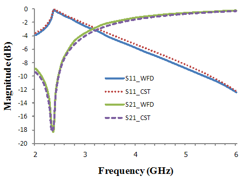 | Figure 4. Comparison of dB(S11) and dB(S21) of the high-pass filter between the WFD and CST tools at  |
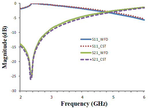 | Figure 5. Comparison of dB(S11) and dB(S21) of the high-pass filter between the WFD and CST tools at  |
4. Design and Implementation of Filters
4.1 Bandpass Filter Design
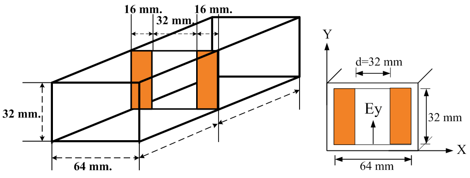
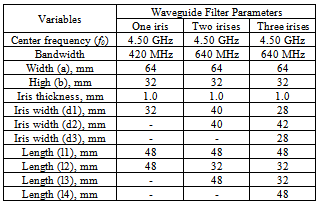
- In this paper, we present the inductive irises in a rectangular metal waveguide by using the simulation program. The usable conductor of irises is a good conductor. The main specifications of the sample bandpass filter for a C-band multiplexer are shown in Figure 6. The bandpass waveguide filter consists of 3 configurations, one iris, two irises and three inductive irises placed in a rectangular waveguide, and is designed by using the formulas of a low-pass Chebyshev prototype filter. The width (a) and height (b) of the waveguide are 64 and 32 mm, respectively. The element values of Chebyshev filters have a ripple = 0.1 dB with 50 Ω of system impedance. We will calculate and optimize each filter parameter to cover the frequency range of 4.20 - 4.84 GHz. The center frequency (f0) = 4.50 GHz, and the bandwidth = 640 MHz, as shown in Table 1.
|
 | Figure 6. The bandpass waveguide iris filter with 3 irises in a cascade |
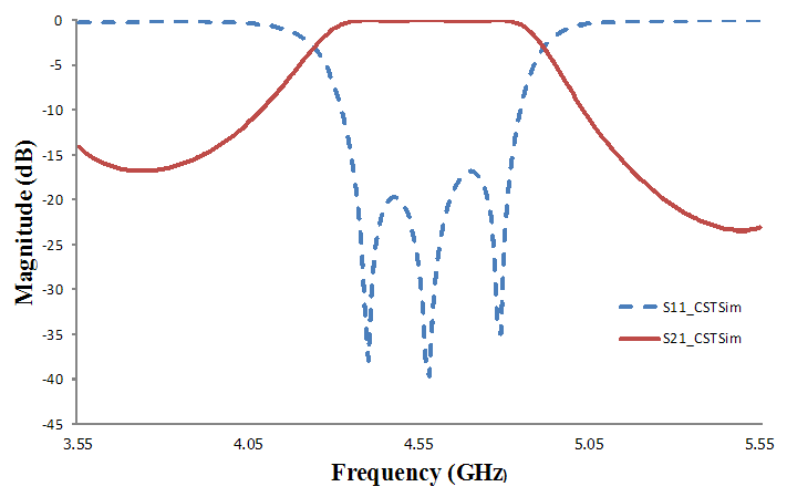 | Figure 7. Simulation results by CST tools |
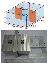 | Figure 8. Simple designed waveguide filter |
4.2. The Implementation of Waveguide Filters
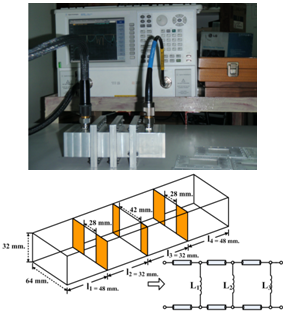
- The sample implementation of bandpass filters in rectangular waveguide is designed by using WFD simulation and CST Microwave Studio® software at the center frequency of approximately 4.5 GHz. The parts were made of aluminum. An example of a simple bandpass filter has been fabricated according to the configuration parameters of an inductive iris in Table 1. This iris was placed within the rectangular waveguide with a width (a) equal to 64 mm, a height (b) equal to 32 mm, and a length equal to 48 mm. Port 1 and port 2 are connected by a λ/4 vertical monopole antenna that is excited by the source of the fundamental mode (TE10), as depicted in Figure 8. Figure 9 shows the experimental setup of the bandpass waveguide filter measured on the N5230C network analyzer (Agilent Technologies).
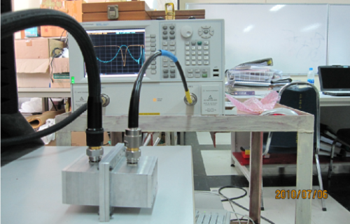 | Figure 9. The experimental setup of the waveguide filter |
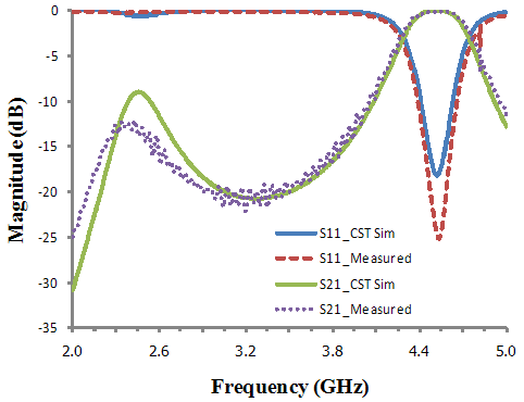 | Figure 10. Comparison of dB(S11) and dB(S21) of the bandpass filter between the CST simulation and the experiment |
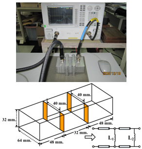 | Figure 11. Configuration of two inductive irises |
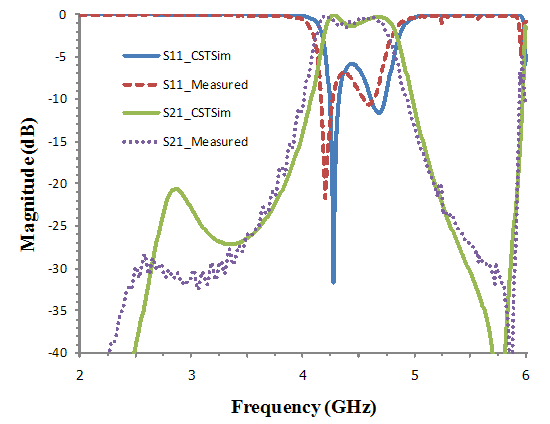 | Figure 12. Simulated and measured results of a filter using two inductive irises |
 | Figure 13. Configuration of three inductive irises |
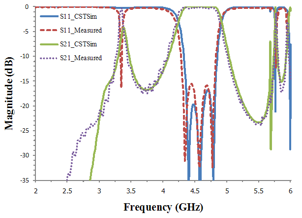 | Figure 14. Simulated and measured results of a filter with 3 inductive irises |
5. Conclusions
- This paper presents the WFD simulation, design and implementation of bandpass filters in rectangular waveguides. The WFD (Waveguide Filter Design) simulation based on an iterative method and wave propagation has been proposed for an inductive iris analysis. The capability of the WFD simulation has been validated. It appears to be an efficient alternative to the CST simulation. The performance of the implemented waveguide filters confirms the suitability of the developed WFD and CST simulation because the error is less than ± 5 % compared with the designed filters. The WFD simulation allows us to reduce the design problem to determinate a bandpass filter structure in the rectangular waveguide with usable frequency range. An interesting aspect of WFD simulation is its application to the design and analysis of different microwave planar circuits. In addition, this simulation can be used as a teaching aid in the microwave engineering education.
ACKNOWLEDGEMENTS
- The authors would like to thank the Faculty of Technical Education, Rajamangala University of Technology Thanyaburi for providing the network analyzer N5230C model of Agilent Technologies and CST Microwave Studio® for measurement and design.