-
Paper Information
- Next Paper
- Previous Paper
- Paper Submission
-
Journal Information
- About This Journal
- Editorial Board
- Current Issue
- Archive
- Author Guidelines
- Contact Us
Electrical and Electronic Engineering
p-ISSN: 2162-9455 e-ISSN: 2162-8459
2012; 2(3): 147-151
doi: 10.5923/j.eee.20120203.07
Meandered Corner Planar Monopole Antenna for UWB Applications
 Abstract
 Reference
 Full-Text PDF
 Full-Text HTML
S. Muzahir Abbas1, Istaqlal Ahmed1, Hamza Nawaz2, Ilyas Saleem1
1Department of Electrical Engineering, CIIT, Islamabad, 44000, Pakistan
2Department of Electrical Engineering, NUST-SEECS, Islamabad, 44000, Pakistan
Correspondence to: Hamza Nawaz, Department of Electrical Engineering, NUST-SEECS, Islamabad, 44000, Pakistan.
| Email: |  |
Copyright © 2012 Scientific & Academic Publishing. All Rights Reserved.
In this paper, an ultra-wideband (UWB) planar monopole antenna is proposed whose design is quite simple in profile. The anticipated antenna is composed of a rectangle with corner truncation applied on each corner, with the slits on three truncated corners and a rectangular slot in the middle of patch. The simulated results are obtained using HFSS (High Frequency Structure Simulator) and furthermore the antenna is fabricated on RT Roger Duroid 5880 with the substrate dimensions of 30 mm2 and the height is 0.787 mm with relative permittivity of 2.2. To acquire the maximum bandwidth, a comprehensive parametric study has been carried out to optimize the dimensions of an antenna. Both; the simulated and measured results attests that antenna has wide bandwidth, which ranges from 1.65 GHz to 17.6 GHz and 1.65GHz to 14.5GHz (S11<-10) respectively, along with fine characteristics like good gain, stable radiation pattern and consistent impedance matching.
Keywords: UWB, Planar-Monopole, Antenna Design, Meandered Corners, Compact Radiating Receiving Element, Transmission Line Feed
Article Outline
1. Introduction
- Considering advantages in the field of communication; like high data rate, low cost, better spectral density and immunity to multi path interferences, UWB has successfully attained attention in the world of wireless communication[1-2] and a lot of researches are interested in the development of the ultra-wideband (UWB) antennas. In order to get access to the UWB spectrum, the transmitted system should radiate signals that carry the bandwidth greater than 500MHz[3]. Federal Communication Commission (FCC) has allocated the frequency band from 3.1 to 10.6GHz[4]. UWB technology is preferred to transmit audio and video signals because of its efficiency, so it is anticipated that different computer and electronic companies will soon adopt UWB technology[5-7].A planar monopole antenna is a well known antenna type. Having a variety of beneficial properties like mechanical durability, conformability, low cross polarized radiations and economical in fabrication, planar monopole antenna has made its way in wireless communication[8-10] as wider bandwidth and adequate impedance matching is frequently achieved by partial ground technique[11-13].In this paper, a compact UWB planar monopole antenna with transmission line feeding is presented. The antenna hasbeen truncated and slotted to enhance the bandwidth by keeping the gain secure. The antenna is providing impedance bandwidth of 15.5 GHz ranging from 1.65 GHz to 17.6 GHz, being a solution for UMTS, Wi-Fi, WiMAX and UWB applications. The parameters of the proposed antenna are investigated numerically and validated theoretically as well as experimentally.
2. Antenna Design
- The design of the proposed UWB planar monopole antenna is shown in Figure 1.
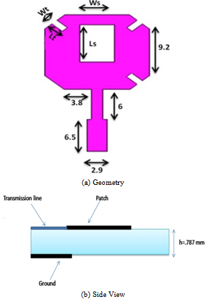 | Figure 1. Design of the proposed antenna |
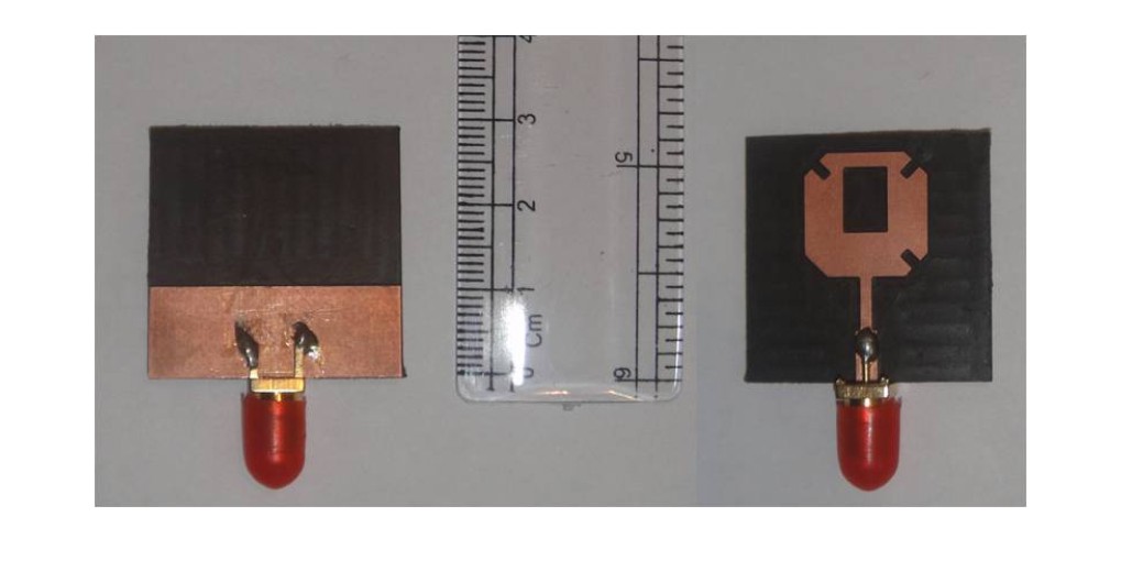 | Figure 2. Front and rear view of fabricated prototype |
3. Results and Analysis
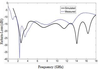 | Figure 3. Simulated and Measured return loss of the proposed antenna |
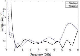 | Figure 4. Simulated and Measured VSWR of the proposed antenna |
3.1. Current Distribution
- The simulated current distributions of the antenna at the frequencies of 1.7, 5, 11, 16 GHz are illustrated in Figure 5. The current distribution is relatively stable over the operating frequency range, which indicates that the radiation characteristics will not be affected that much with the change in frequency.
3.2. Radiation Patterns
- The simulated radiation patterns of the antenna at frequencies of 1.7, 5, 11 and 16 GHz are illustrated in Figure 6. Red and blue patterns depict H-field and E-field of the proposed antenna respectively. Good Omni-directional patterns in xy-plane, yz-plane and zx-plane have been obtained. For achieving the pattern of xy-plane, theta has been set as 90deg for all values of pi. Similarly to show the trend of radiations in yz-plane pi has been set as 90deg for all values of theta and to have radiation trend in zx-plane all values of theta are focused for pi=0deg. Red and Blue patterns in Figure 6 depict H-field and E-field respectively.
3.3. Parametric Analysis
- The parametric analysis is carried out to provide engineers with more details of the antenna and a trend adopted by the parameters used in configuration of antenna. The impedance bandwidths of -10 dB s-parameters are investigated. Results of the parametric analysis for the various parameters are presented in Figure 7. It has been found that the parameters Ls, Ws, Wt are playing their role in betterment of bandwidth and controlling of return-loss, but the main trend or can say behaviour is set by Lt, which mainly determine the operating band.
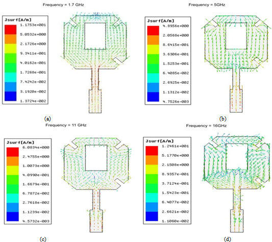 | Figure 5. Distribution of electric current for the proposed antenna at various frequencies |
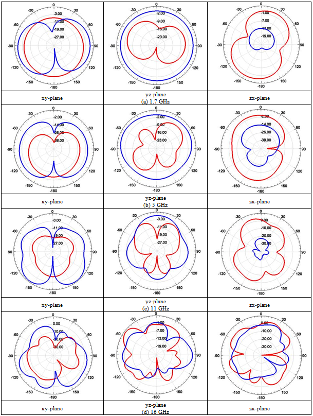 | Figure 6. Simulated radiation patterns of the proposed antenna at 1.7, 5, 11 and 16 GHz |
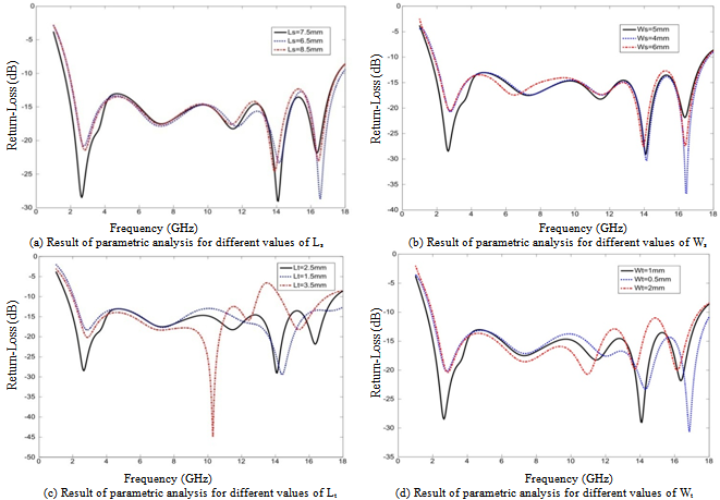 | Figure 7. Effect of geometrical parameters of the proposed antenna |
4. Conclusions
- Antenna design presented is capable for the functionality of UWB. The partial ground plane is used to have fine radiation patterns and addition of slits on truncated corners acclaimed frequency spectrum from 1.65 GHz to 17.6 GHz in HFSS and from 1.65 GHz to 14.5 GHz using network analyser. The parametric study confirmed that the length, width, and position of slits and central slot can control s-parameters. Most of the UWB antennas have difficulty to achieve stable gain with wide band at the same time but, our proposed UWB antenna not only fulfils the FCC assigned frequency band but also capture low frequency bands, despite of being small sized.