-
Paper Information
- Next Paper
- Paper Submission
-
Journal Information
- About This Journal
- Editorial Board
- Current Issue
- Archive
- Author Guidelines
- Contact Us
Electrical and Electronic Engineering
p-ISSN: 2162-9455 e-ISSN: 2162-8459
2012; 2(3): 88-95
doi: 10.5923/j.eee.20120203.01
Radiation Characteristics of Cylindrical Dielectric Resonator Antenna Mounted on Superquadric Cylindrical Body
S.H. Zainud-Deen1, Noha A. El-Shalaby2, K.H. Awadalla1
1Faculty of Electronic Engineering, Menoufia University, Menoufia, 32952, Egypt
2Faculty of Engineering, Kafrelsheikh University, Kafrelsheikh, 3317, Egypt
Correspondence to: Noha A. El-Shalaby, Faculty of Engineering, Kafrelsheikh University, Kafrelsheikh, 3317, Egypt.
| Email: |  |
Copyright © 2012 Scientific & Academic Publishing. All Rights Reserved.
Characteristics of cylindrical dielectric resonator antenna on (CDRA) on superquadric cylindrical body are discussed in this paper. Curvature effects on radiation characteristics in different planes of (CDRA), the reflection coefficient, the input impedance, The co-polarization and the cross-polarization characteristics, gain of the antenna, are calculated and discussed for different values of ν squareness parameter. Then show effect of changing the aspect ratio B/A on the reflection coefficient and the input impedance. The proposed antennas are numerically investigated using finite element method and the finite integration technique.
Keywords: DRA, CDRA, FEM, FIT
1. Introduction
- The dielectric resonator antenna (DRA) concept was first proposed in 19. Many practical applications of DRA mounted on planar surfaces were demonstrated[1-7]. DRA can be of any shape, but in practical applications, rectangular and cylindrical shapes are most common. Because of its simple geometry, DRA offers many advantages, such as low loss, easy of excitation, small size and broad beam characteristics. Recently, the radiation characteristics of cylindrical DRA mounted on or embedded in circular cylindrical ground plane are investigated[8,9].In this paper, for the first time (to the best of our knowledge), CDRA mounted on superquadric cylindrical ground plane is implemented. Superquadrics are a powerful family of parametric shapes that allow complex solids and surfaces to be constructed and altered easily from a small number of interactive parameters. This kind of antennas can be of great interest for applications on the bodies of missiles, aircrafts and spacecrafts that have no planar surfaces on portions of their bodies. The finite element method (FEM)[10,11] is used to calculate the reflection coefficient, the input impedance, impedance bandwidth, and copolarized and cross-polarized field components in different planes. The metallic ground plane is assumed to be perfect conductor and the thickness is neglected since it is much less than that of the operating wavelength. The calculated results arevalidated using the finite integration technique (FIT)[12,13].
2. Antenna Structure
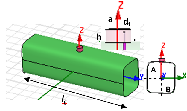 | Figure 1. The geometry of CDRA mounted on superquadric cylinder ground plane structure for ν= 4 |
 | (1) |
 | (2) |
 The parameter β is in the range (0≤β≤2π). An important feature of this particular representation is the fact that equal divisions in the parameter β results in reasonably equal values of arc length for the sub- different antenna configurations through the variation of parameters A, B, and ν starting from circular (ellipse) to square (rectangular) cross sectional area. The CDRA with dielectric constant εr =12 is used. It has radius "a", of 2.75cm and a height "h", of .A coaxial probe with radius of excites the antenna. The probe is located off the centre by df =1.4 cm with a height "hf", of 2cm.
3. Numerical Results
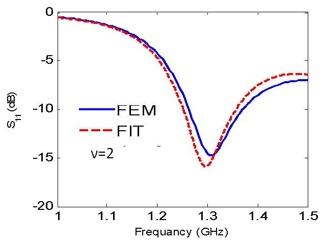 | Figure 2. Reflection coefficient versus Frequency for lg = 50cm, A = B =12.5cm |
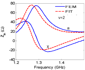 | Figure 3. Input impedance versus frequency for lg= 50cm, A = B =12.5cm |
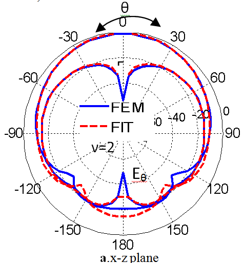 | Figure 4. The radiation patterns in different planes at f = 1.305GHz |
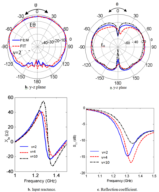 | Figure 5. The reflection coefficient and input impedance versus the frequency for A =B=125 mm at different values of ν |
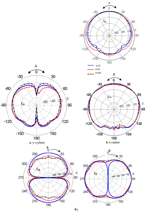 | Figure 6. The radiation pattern in all planes for different values of ν, at frequency= 1.305GHz |
 | (3) |
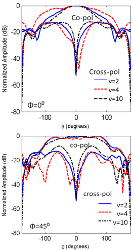 | Figure 7. The copolarized and the cross polarized field components for different values of ν at frequency= 1.305GHz |
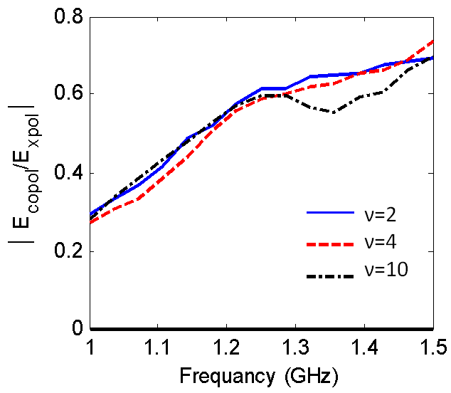 | Figure 8. Cross-polarization level versus the resonance frequency |
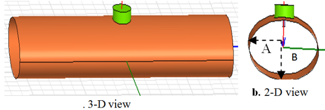 | Figure 9. The geometry of CDRA mounted on superquadric cylindrical ground plane structure, A= 2B and ν= 2 |
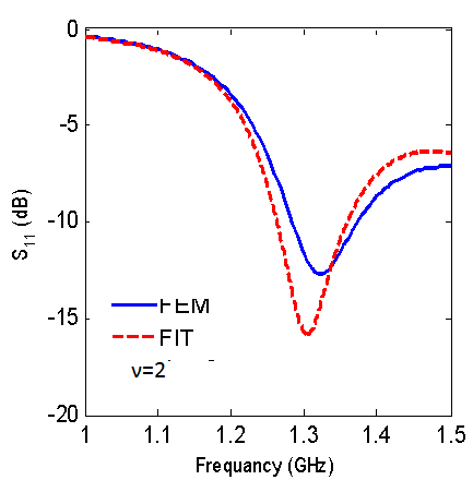 | Figure 10. Reflection coefficient versus frequency for lg=50cm, A=2B=12.5cm |
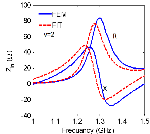 | Figure 11. Input impedance versus frequency for lg=50cm, A=2B=12.5cm |
 | Figure 12. The radiation patterns in all planes at f= 1.32GHz |
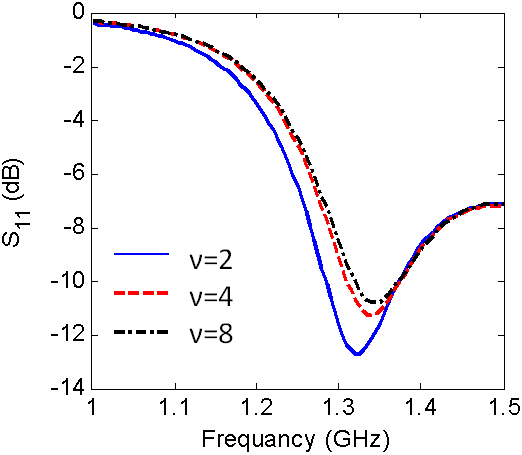 | Figure 13. Reflection coefficient versus frequency for different values of ν |
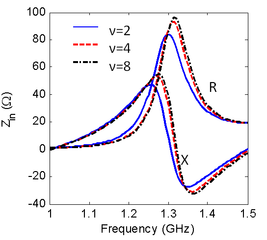 | Figure 14. The variation of input impedance Versus the frequency for A=2B=12.5cm |
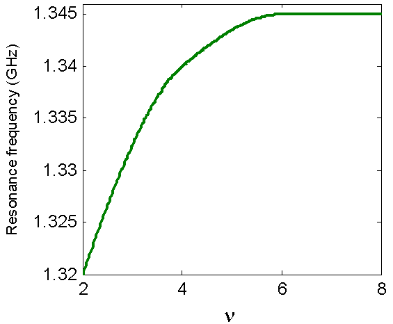 | Figure 15. The resonance frequency versus the squareness parameter ν, for A=2B=12.5cm |
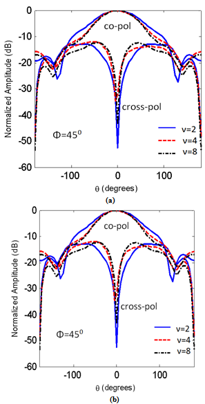 | Figure 16.The copolarized and the cross polarized field components for different values of ν. at f= 32GHz |
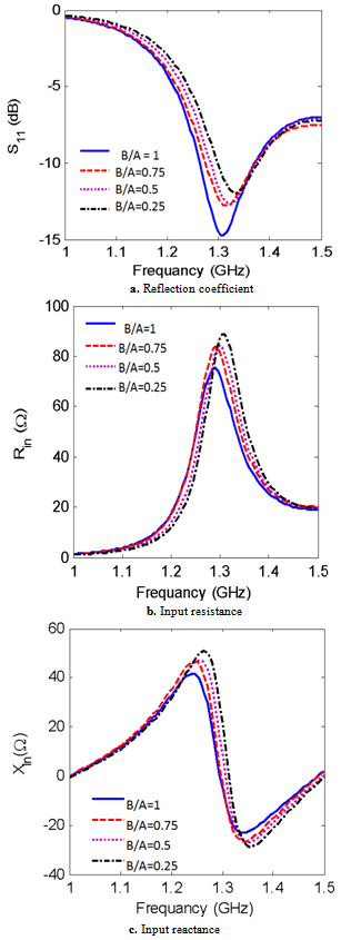 | Figure 17. The reflection coefficient and input impedance versus frequency for different values of A/B and ν =2 |
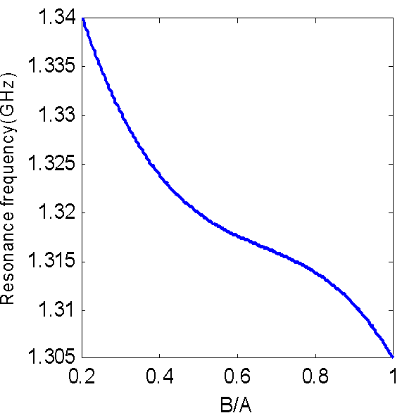 | Figure 18. The aspect ratio versus resonance frequency, ν = 2, A = 2B = 12.5 cm |
4. Conclusions
- The finite element method and finite integration technique are used to calculate the radiation characteristics of CDRA mounted on superquadric cylindrical body. The effects of changing the value of squareness parameter, ν, on the reflection coefficient, input impedance, resonant frequency, impedance bandwidth, and radiation patterns in different planes are demonstrated. It is seen that as the value of ν increases the resonance frequency increases, the magnitudes of the input resistance, and reactance increase. Also, the cross-polarized field component is increased. The resonance frequency is decreased with increasing the ratio of B/A. However, from Figs. 5,6,7,13,14,15,16,17 and 18, the effect of changing the squareness parameter " ν" from 2 to ∞ and the aspect ratio B/A from 0 to 1 are not causing any significant effect on the characteristics of the CDRA
 Abstract
 Reference
 Full-Text PDF
 Full-Text HTML