-
Paper Information
- Next Paper
- Previous Paper
- Paper Submission
-
Journal Information
- About This Journal
- Editorial Board
- Current Issue
- Archive
- Author Guidelines
- Contact Us
Electrical and Electronic Engineering
p-ISSN: 2162-9455 e-ISSN: 2162-8459
2012; 2(2): 78-81
doi: 10.5923/j.eee.20120202.14
Dual-Frequency Microstrip Antenna for Wireless Applications and Effect on Fraud
 Abstract
 Reference
 Full-Text PDF
 Full-Text HTML
Arpita Sen , Neela Chattoraj
Electronics and Communication Engineering Department, Birla Institute of Technology, Mesra, Ranchi, 835215, India
Correspondence to: Arpita Sen , Electronics and Communication Engineering Department, Birla Institute of Technology, Mesra, Ranchi, 835215, India.
| Email: |  |
Copyright © 2012 Scientific & Academic Publishing. All Rights Reserved.
The design of a microstrip patch antenna is reported which can be operated at GPS (Global Positioning System) and Bluetooth frequencies. Very small thin microstrip antenna is excited by a co-axial SMA connector to produce centre frequency of a Bluetooth system and then a thin parasitic microstrip patch is coupled with this patch to excite the centre frequency of GPS system. The simulated results using IE3D software are supported by measurement. Also, some effects of such antennas on fraud have been studied. Some of the frauds like Increase in Subscription Fraud, Unattended High Usage Fraud, Increase in Roaming Fraud have been described in this paper.
Keywords: Microstrip Patch Antenna, Dual Frequency, Compact, Multi-Frequency, Bluetooth, GPS
Article Outline
1. Introduction
- The increasing use of microwave mobile communication systems demand the antennas for different systems and standards with properties like reduced size, broadband, multiband operation, moderate gain etc. Two important frequency bands for wireless communications are Global Positioning System or GPS (1.575 GHz) and Bluetooth (2.4 GHz – 2.484 GHz). The GPS system uses low Earth orbiting satellites that transmit signals continuously to the Earth based receivers. There are two categories of GPS services: civilian and military. Civilian GPS system operates at a center frequency of 1575.42 MHz (L1 band) with a bandwidth of 20 MHz. The require polarization is circularly polarized with axial ratio of 3dB or better and required antenna gain is 4 dBi. A user terminal may use linearly polarized antenna, but in that case it will suffer 3 dB power loss. The radiation pattern of the GPS antenna should have a wide hemispherical coverage in the upper half plane. Bluetooth is a well-established short-distance (10 meters) wireless communications standard which uses 2.4 GHz – 2.484 GHz frequency of ISM (Industrial, Scientific and Medical) band with a bandwidth of 84 MHz. Bluetooth communications uses omnidirectional antenna, but linearly polarized directional antenna can be used for short distance communication. Because of many attractive features, microstrip patch antennas have received considerable attention for wireless communication handset terminals and for mobile vehicular terminals. Literatures are available for microstrip patch antennas with parasitic patches and these types of patches are also investigated for mobile communication. In this paper, the design of a microstrip patch antenna is reported which can be operated at GPS and Bluetooth frequencies. The antenna structure consists of a very thin microstrip patch excited by a co-axial connector and a thin parasitic patch, separated by a certain distance and coupled to the driven patch. The simulation of the antenna was performed by IE3D software and after fabrication the simulated results were verified by measurement.
2. Antenna Design and Measurement
- Very small thin microstrip antenna is excited by a co-axial SMA connector to produce centre frequency of a Bluetooth system (2.442 GHz) and the correct feed position is determined using IE3D simulation for impedance matching. Then a thin parasitic microstrip patch is coupled with this patch to excite the centre frequency of GPS system (1.575 GHz). The antenna geometry is shown in Fig.1. The simulated results are verified by measurement after fabricating the antenna on Glass Epoxy substrate of dielectric constant of 4.36, substrate height of 1.57 mm, loss tangent of 0.001. The separation between driven patch and parasitic patch was 0.5 mm. The centre of parasitic patch is shifted upward from the centre of driven patch by a distance of 11 mm. The driven patch was fed by a co-axial SMA connector at a distance of 1.3 mm downward from the centre of the patch and at the edge of the driven patch as shown in Fig. 1. These dimensions are optimum dimensions for which the best performances of the antenna at both the frequencies were achieved in simulation. For antenna design, IE3D simulation software is used, which is full wave electromagnetic simulation software for the microwave and millimeter wave integrated circuits. The primary formulation of the IE3D software is an integral equation obtained through the use of Green’s function. The simulation using IE3D, takes into account the effect of co-axial SMA connector, by which the antenna was fed. The simulated results for radiation patterns of the antenna at GPS and Bluetooth frequencies are shown in Fig.2. Broadside and linearly polarized radiation patterns are obtained at both the frequencies.
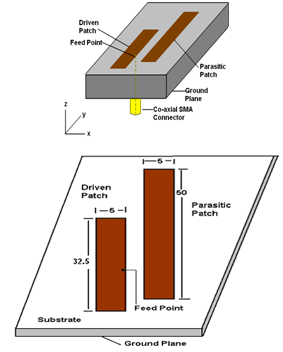 | Figure 1. Dual-frequency microstrip antenna (all dimensions are in mm) |
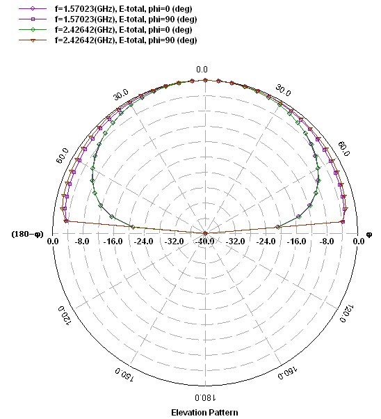 | Figure 2. Simulated radiation pattern of the antenna |
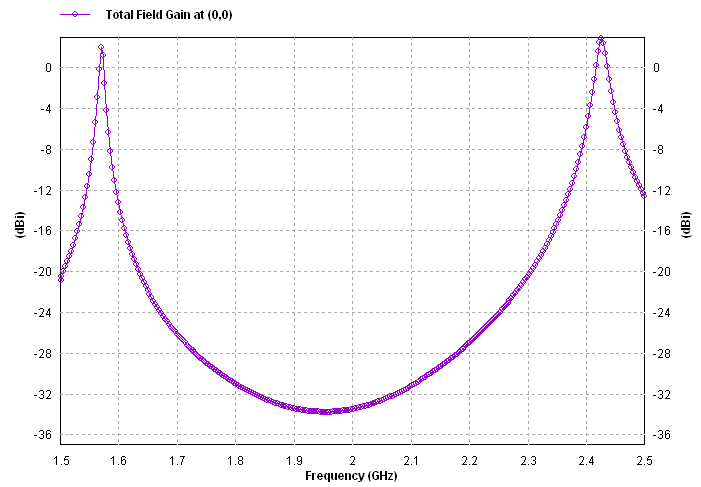 | Figure 3. Simulated gain of the antenna |
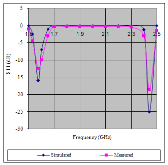 | Figure 4. Simulated and measured reflection coefficients of the antenna |
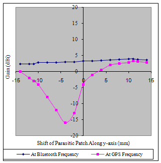 | Figure 5. Variation of gain (Simulated) with the relative shift (along y-axis) of parasitic patch with respect to the driven patch |
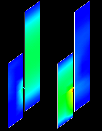 | Figure 6. Current Distribution at 1.575 GHz and 2.45 GHz |
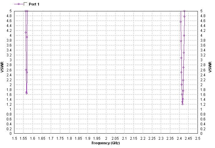 | Figure 7. VSWR of the antenna |
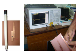 | Figure 8. Antenna Design and Measurement |
3. Effect of Multi-Frequency Antennas on Fraud
- Multi-frequency antennas have a large number of advantages, like the proposed antenna that supports GPS and Bluetooth in the same device, can be used for:Bluetooth GPS transmitter - where it can broadcast position data to a paired Bluetooth receiver or,Mobile Marketing – that gives the entrepreneur the advantage of geo-location and sending location-specific messages to users, using GPS and Bluetooth technologyBut, this availability of multiple services is one of the root causes for increase in frauds these days. Fraud is a deliberate misrepresentation that causes a person or business to suffer damages, often in the form of monetary losses.Assuming that the primary reason for a fraudulent activity in case of accessing a wireless network is anonymity, many fraudsters have a vested interest in being able to penetrate wireless networks. Other goals can be the disruption of corporate infrastructures and the wireless network clearly has the access required to achieve this goal. More so, because the subscribers are getting multiple services at one go, with the availability of multi-frequency antennas. Some of such fraudulent activities are listed as follows:
3.1. Increase in Subscription Fraud
- Attempt to get services, with false identity and without the intension of paying for the service is termed as subscription fraud. And, the fraudster will have more benefits out of a single handset and a single connection.
3.2. Unattended High Usage Fraud
- Since the subscriber will have multiple services with multi-frequency enabled handset, for e.g., VOICE and GPRS, s/he may ditch the fraud management solution by not crossing the threshold of a single service but, doing distributed usage (for e.g., if we wants to make 2 hrs call, he will use the voice service i.e. GSM for 30 minutes and VOIP i.e. GPRS for 1.5 hrs). This is high usage (just below the threshold) for each service.
3.3. Increase in Roaming Fraud
- For example, GSM service is in the 900-MHz band for Europe & Asia and 1900-MHz band for the United States. Thus, if the user has a handset with dual frequency with these two frequencies, he can roam between Europe and Asia and do fraudulent activities.
4. Conclusions
- The design and performance of a dual-frequency microstrip antenna for the application in GPS and Bluetooth systems are described here. The simulated results are verified by measurement. Also, we have studied here some of the negative effects, such as fraud, that can increase with multi-frequency antennas. These should be kept in mind while designing any Fraud Management solution for operations where multiple services are available.