-
Paper Information
- Paper Submission
-
Journal Information
- About This Journal
- Editorial Board
- Current Issue
- Archive
- Author Guidelines
- Contact Us
Electrical and Electronic Engineering
p-ISSN: 2162-9455 e-ISSN: 2162-8459
2012; 2(2): 54-59
doi:10.5923/j.eee.20120202.10
Ferroresonance Elimination in 275kV Substation
 Abstract
 Reference
 Full-Text PDF
 Full-text HTML
Hamid Radmanesh
Electrical Engineering Department, Islamic Azad University, Takestan Branch, Takestan, Ghazvin, Iran
Correspondence to: Hamid Radmanesh, Electrical Engineering Department, Islamic Azad University, Takestan Branch, Takestan, Ghazvin, Iran.
| Email: |  |
Copyright © 2012 Scientific & Academic Publishing. All Rights Reserved.
This work studies the non-conventional ferroresonance oscillation in the 275kV substation. Voltage transformer (VT) which is used in this substation has a 100VA capacity and magnetization characteristic of it was modeled by single-value two-term polynomial with q=7. In this study, at first ferroresonance oscillation in VT has been introduced, then effect of Metal Oxide Varistor (MOV) on limiting these nonlinear overvoltages is investigated. It has been shown for some parameters values, MOV cannot control the ferroresonance. So, by connecting the neutral earth resistance (NR) to the system grounding, non-conventional oscillation has been controlled for all value of system parameters. Simulation results show that considering neutral earth resistance exhibit great controlling of ferroresonance overvoltages. It is also shows by using this resistance, system exhibit less sensitivity to the changing the parameters value of the power system.
Keywords: Ferroresonance Oscillation, Stabilizing, Chaos Control, Voltage Transformer, MOV, Neutral Earth Resistance
Cite this paper: Hamid Radmanesh, Ferroresonance Elimination in 275kV Substation, Electrical and Electronic Engineering, Vol. 2 No. 2, 2012, pp. 54-59. doi: 10.5923/j.eee.20120202.10.
Article Outline
1. Introduction
- Ferroresonance is a complex nonlinear electrical phenomenon which can cause dielectric and thermal problems to the power system components. Electrical systems exhibiting ferroresonant behaviour are categorized as nonlinear dynamical systems. Therefore conventional linear solutions cannot be applied to study ferroresonance. The prediction of ferroresonance is achieved by detailed modeling using a digital computer transient analysis program[1]. In linear resonance, current and voltage are linearly related and are frequency dependent. In the case of ferroresonance it is characterized by a sudden jump of voltage or current from one stable operating state to another one. The relationship between voltage and current is depends not only on frequency but also on other factors such as voltage magnitude, initial magnetic flux condition of the transformer iron core, total loss in the ferroresonant circuit and moment of switching[2].VT ferroresonance from an energy transfer standpoint is given in[3]. In this paper, a new approach to determine whether ferroresonance can occur is developed, based on the energy transferred from the system to the voltage transformer during the switching transient. Discussion of modeling and analysis guidelines for slow transients has been given in[4]. Fast ferroresonance suppression of coupling capacitor voltage transformers (CCVT) was done in[5]. This paper describes a procedure for fast suppression of the phenomenon of ferroresonance in CCVT without major change in the design. It will be shown that it is possible to adjust parameters of the secondary overvoltage protection and the filter circuit so that the ferroresonance can be cleared in a very short time interval. A systematical method for suppressing ferroresonance at neutral-grounded substations is given in[6]. In this paper, the scheme for suppressing the ferroresonance is to insert resistance, made from parallel-connected resistors, in to the PT’s wye secondary circuit. Sensitivity studies on power transformer ferroresonance of a 400 kV double circuit are given in[7]. Novel analytical solution to fundamental ferroresonance in[8] investigated a major problem with the traditional excitation characteristic (TEC) of nonlinear inductors, in that the TEC contains harmonic voltages and/or currents, and has been used the way as if it were made up of pure fundamental voltage and current. Stability domain calculations of period-1 ferroresonance in a nonlinear resonant circuit have been investigated in[9]. Application of wavelet transform and MLP neural network for ferroresonance identification was done in[10]. In this paper an efficient method for detection of ferroresonance in distribution transformer based on wavelet transform is presented. Impacts of transformer core hysteresis formation on stability domain of ferroresonance modes were done in[11]. In this paper, impacts of various formations of hysteresis on the stability domain of ferroresonance modes of a VT have been studied. 2-D finite-element electromagnetic analysis of an autotransformer experiencing ferroresonance was given in[12]. Experimental and simulation analysis of ferroresonance in single-phase transformers considering magnetic hysteresis effects is investigated in[13]. A new modeling of MATLAB transformer for accurate simulation of ferroresonance shows a new modeling of transformers in Simulink/MATLAB enabling to simulate slow transients more accurate than the existing models used in the software[14]. Effect of Magnetizing Curve Nonlinearity Index on the Occurring Chaotic Ferroresonance Oscillation in Autotransformers has been studied in[17]. In current paper, MOV and NR connected devices are used as a control method for stabilizing of unstable and high amplitude ferroresonance oscillation. Using of these methods result improving voltage waveform which leads to protection from insulation, fuses and switchgears. This paper organized as follow: At first the reasons of occurring ferroresonance in transformers is described. Then various types of ferroresonance in VT are explained. Then general introducing of controlling ferroresonance by considering neutral earth resistance and using it in current problem is shown.
2. Power System Modeling without Neutral Resistance
- Ferroresonance can occur where VTs are connected to isolated sections of bus bars. Energy is coupled via the inter-circuit capacitance of the parallel lines or open circuit breaker grading capacitance. Specifically, the connection of VTs to isolated section of bus bar i.e. to a low capacitance should be avoided[15].
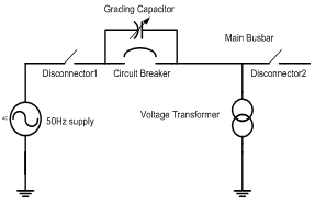 | Figure 1. System one line diagram arrangement resulting to VT ferroresonance[15] |
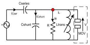 | Figure 2. Basic reduced equivalent ferroresonance circuit connecting MOV |
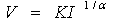
 where the coefficient of the linear term (a) corresponds closely to the reciprocal of the inductance
 . However, for very high currents the iron core might be driven into saturation and the flux-current characteristic becomes highly nonlinear, here the
  characteristic of the voltage transformer is modeled as in[15] by the polynomial
  | (1) |
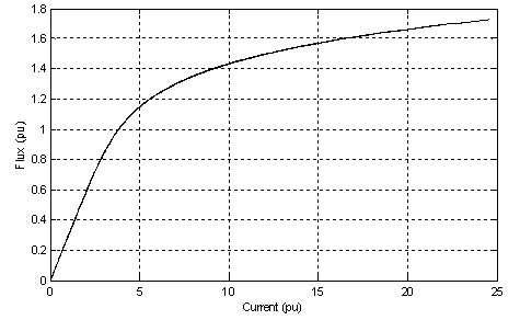 | Figure 3. Flux- current characteristic of transformer core |
3. Metal Oxide Varistor Model
- MOV is highly nonlinear resistor used to protect power equipment against overvoltages. The nonlinear V-I characteristic of each column of the MOV is modeled by combination of the exponential functions which is shown in (2).
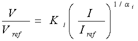 | (2) |
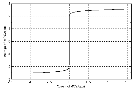 | Figure 4. V-I characteristic of MOV |
 | (3) |
 | (4) |
 | (5) |
 | (6) |
 | (7) |
|
|
4. System Descriptions Connecting Neutral Earth Resistance
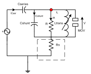 | Figure 5. Basic reduced equivalent ferroresonance circuit including MOV and neutral earth resistance |
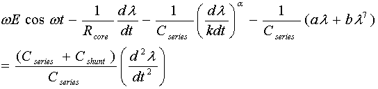
 The differential equation for the circuit in Fig.5 can be presented as follows:
 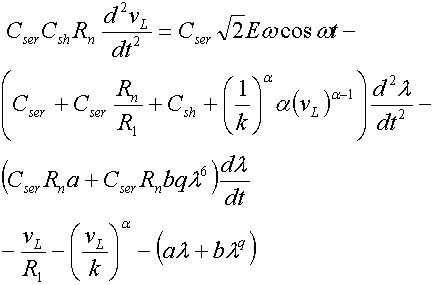 | (8) |
5. Simulation Results
- In this section of simulation, three state of ferroresonance have been studied in two cases, without considering neutral earth resistance and considering neutral resistance.Simulation results without considering neutral earth resistancePhase space and waveform of voltage for subharmonic response were shown in Figs. 6.a and 6.b. The phase plane diagram clearly shows the effect of MOV on the system behavior, MOV clamps the ferroresonance overvoltages on 2.3p.u and doesn’t allow to overvoltages that across from this point. According to the Fig.3, V-I characteristic of MOV has been shown when voltage of transformer has been crossed from 2.2p.u, MOV causes across high current from its terminal and overvoltages has been damped by this nonlinear varistor. It is shown that overvoltages clamps by considering MOV in parallel to the transformer.
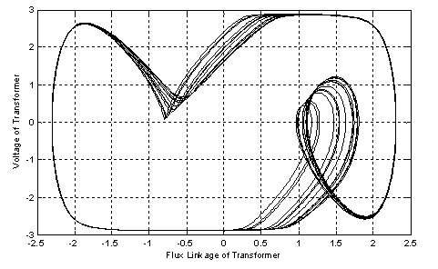 | Figure 6. a) Phase plan diagram for fundamental resonance motion without neutral earth resistance effect |
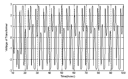 | Figure 6. b) Time domain simulation for fundamental resonance motion without neutral earth resistance effect |
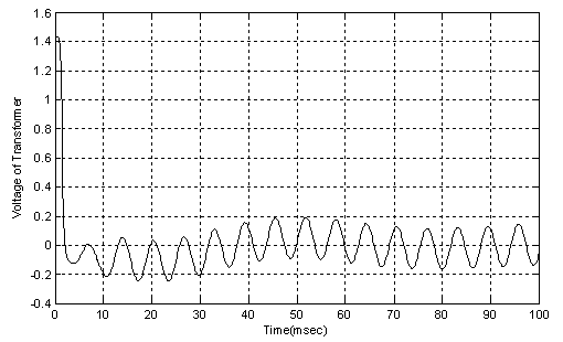 | Figure 7. b) Time domain simulation for quasi-periodic motion considering neutral earth resistance effect |
6. Bifurcation Diagram Analysis
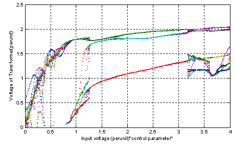 | Figure 8. a) Bifurcation diagram considering MOV effect |
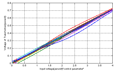 | Figure 8. b) Bifurcation diagram considering neutral earth resistance and MOV |
7. Conclusions
- In this paper, ferroresonance overvoltages have been studied in the VTs. At first, effect of MOV on controlling these phenomena is studied. It is shown MOV can clamp the ferroresonance oscillation but it cannot control these nonlinear overvoltages for all parameters values. Then, it has been shown that system is greatly affected by neutral earth resistance. The presence of the neutral resistance results in clamping the ferroresonance oscillations. Neutral resistance successfully, suppresses or eliminates the chaotic oscillation in the power system. Finally, the system shows less sensitivity to changing in the system parameters.