-
Paper Information
- Next Paper
- Previous Paper
- Paper Submission
-
Journal Information
- About This Journal
- Editorial Board
- Current Issue
- Archive
- Author Guidelines
- Contact Us
Electrical and Electronic Engineering
p-ISSN: 2162-9455 e-ISSN: 2162-8459
2012; 2(2): 43-48
doi: 10.5923/j.eee.20120202.08
Automatic Inspection System for Electric Motors with Integrated Bus Interface
 Abstract
 Reference
 Full-Text PDF
 Full-Text HTML
András Lelkes
GEFEG-NECKAR Antriebssysteme GmbH, Gosheim, D-78559, Germany
Correspondence to: András Lelkes , GEFEG-NECKAR Antriebssysteme GmbH, Gosheim, D-78559, Germany.
| Email: |  |
Copyright © 2012 Scientific & Academic Publishing. All Rights Reserved.
This paper describes an automatic test system for small power electric motors with integrated intelligent control unit. The testing concept utilizes the sensors integrated in the motor and the communication capabilities of the drive. Therefore, the motors can be tested quickly, yet thoroughly during manufacturing without the need for cost intensive test stands.
Keywords: Electric Machines, Variable Speed Drives, Field Bus, Automatic Test Equipment, Quality Management
Article Outline
1. Introduction
- The company GEFEG-NECKAR Antriebssysteme is successor of the motor manufacturers Gefeg, founded in 1948, and Neckar Kleinstmotoren, founded in 1967. The latter produced compact brushless dc motors with integrated electronic motor control since 1995.In 2005, the merged company started the development of a new electronic platform with the capability of bus communication. Feedback from customers showed that CANopen® was a good choice for a high-performance but cost-effective bus solutions.The integration of motor and control unit makes elegant and compact drive solutions for numerous industrial applications possible. The drives decrease wiring effort in the system and space requirement in the electronics cabinet. Additionally, the integrated bus interface of these motors enables an efficient automatic final test in the motor production line without the need for cost intensive test stands.
2. Compact Drives with Integrated CAN Interface
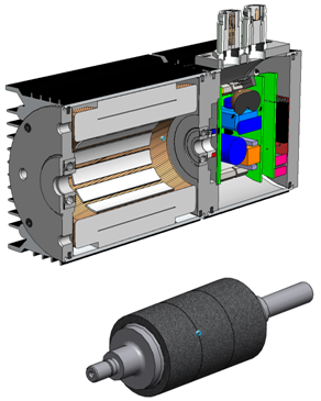
- The first application of the new, bus capable electronic platform has been a compact BLDC drive. These motors have long service life as a result of the brushless technique, high efficiency by high-quality rare earth magnets and high environmental protecting class by compact, closed construction (Figure 1). These motors can be combined, similar to all motors of this manufacturer, with worm, spur and planetary gears, with brakes and with shaft encoders.The control algorithm is implemented in a low-cost DSP controller (dsPIC33F). The rotor position is detected by three Hall sensors. This position information serves for proper electronic commutation of the brushless motor. Additionally, the Hall sensors are used for speed measurement and for closed-loop speed control. The 24V power module is based on SMD-MOSFET transistors. They are soldered on a PCB from aluminum enabling proper cooling.
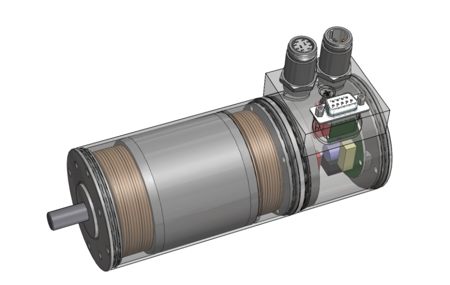 | Figure 1. Brushless motor with integrated CANopen® interface (MC 663) |
2.1. Development of a New BLDC Motor Family
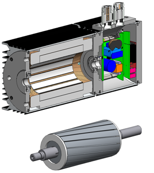
- By optimizing the magnet circuit and by implementation of a new winding technology, a new high-performance high-efficiency BLDC motor family was developed. The first member of this family is a compact brushless DC motor with a diameter of 68 mm (MQ 667, Figure 2).In comparison to its ancestor with the same diameter (M 663), axial length could be decreased by 15%, torque increased by 60% and cogging torque reduced considerably.
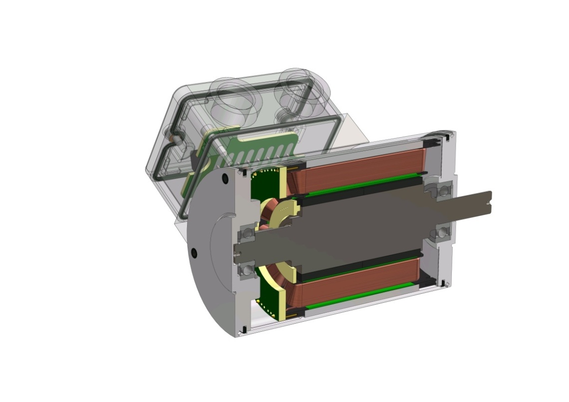 | Figure 2. Newly developed high-performance BLDC motor (MQ 667) |
2.2. PMDC motors with integrated CAN interface
- The electronic platform with CAN interface can be used to control permanent magnet DC motors, too. In spite of mechanical commutation, these drives also contain Hall sensors for the position detection. These sensors deliver speed information for the closed-loop speed control.
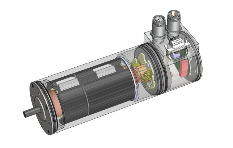 | Figure 3. motor with integrated CAN interface (PC 6355) |
2.3. External Motor Control Unit with Integrated CAN Interface
- By integrating all components of the system such as power unit, motor control unit, measurement system and bus interface, wiring and planning effort is reduced to a minimum. Of the elaborate wiring system for the individual components, only the supply cable and the field bus cable remain. Therefore, the availability of the system increases. Furthermore, the space required in the electronics cabinet is reduced. Nevertheless, there are applications where the integrated solution is not preferable. The reason can be that environmental temperature is too high or that installation space is strongly limited.To cover such applications, an external control unit with CAN interface was developed (Figure 4). This control unit is based virtually on the same hardware and firmware as used in the integrated solutions. In doing so, the platform allows the users to control PMDC and BLDC motors in the same way – no matter whether the control unit is located in a switch cabinet or integrated into the motor.
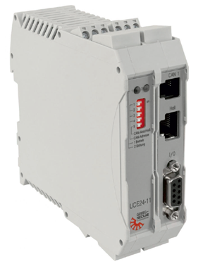 | Figure 4. External unit with integrated CAN interface for controlling BLDC and PMDC motors (UCE24-11) |
2.4. Electronically Commutated Motors for 230V 50Hz Mains
- At safety low voltage drives, the AC mains voltage has to be converted in two steps. A switch-mode AC/DC converter generates a safety-low voltage (e.g. 24 V) from the 230V 50 Hz AC voltages. From this DC voltage, the commutation unit generates a three-phase AC voltage system with variable amplitude and frequency for the motor windings.Using a commutation unit for direct mains operation, investment spending, system complexity and power dissipation can be reduced. For this reason, such commutation electronics were developed based on an intelligent power module (Figure 5).
 | Figure 5. Commutation unit with CAN interface for direct 230V/50Hz supply |
2.5. Induction Motor with Integrated CAN Interface
- Induction motors have a lower nominal torque and a lower level of efficiency than electronically commutated motors do. However, induction motors do not need high prized rare earth magnets for their production. For speed variable drives, the induction motor can be supplied by a converter with variable frequency.With a modified firmware, the commutation unit of the EC motor can act as a frequency converter for three-phase induction motors. By integrating this unit into the motor housing, a very compact variable speed induction drive can be achieved (Figure 7).Benefits of this drive are bus capability (CANopen®) and closed-loop speed control, similar to those of all the other members of the large family of drives with the same electronic platform.
 | Figure 6. EC motor with integrated CAN interface for 230V/50Hz supply (MCN 963) |
 | Figure 7. Variable speed induction drive with integrated CAN interface (ACN 983) |
3. Test System for Integrated Drives
3.1. Software for Manual Testing
- For manual testing of the motors with integrated control unit and bus interface, the PC software “MotorMonitor” for Windows® based computers has been developed. The software is written in the programming language C#. It needs only a CAN/USB adapter to communicate with the motor via CANopen® protocol (Drive Profile DSP-402).
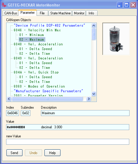 | Figure 8. Graphical user interface of the commissioning software “MotorMonitor”, tab card “Parameter” |
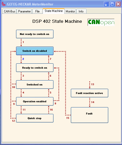 | Figure 9. Tab card “State Machine” of the commissioning software |
3.2. Automatic inspection system integrated in the production process
- The integrated bus capable electronic control unit enables an easy, cost effective but detailed test of these motors in the production line. For the final test, a new inspection system has been developed. It utilizes a standardized protocol to communicate with the integrated electronic platform (CANopen® Drive Profile DSP 402). The test program is based on the routines of the commissioning software “MotorMonitor”.Without requiring any expensive test station, it is now possible to test the drives automatically. There is no need for any additional sensors for testing, because the integrated intelligent control unit contains all the sensors needed for an adequate test (Figure 10).
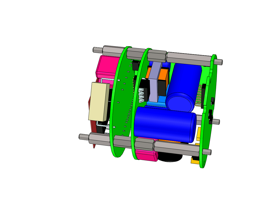
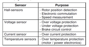 | Figure 10. Integrated sensors of the control unit |
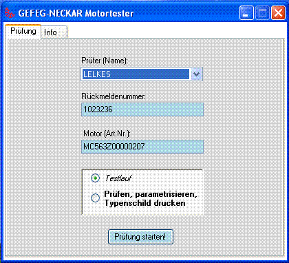 | Figure 11. Graphical user interface of the automatic inspection system |
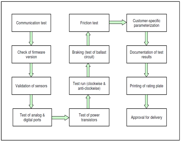 | Figure 12. Steps of the test procedure |
4. Conclusions
- An automatic test system for small power electric motors with integrated CANopen® interface was developed. The testing concept utilizes the sensors integrated in the motor and the communication capabilities of the drive. With this inspection system, the produced motors can be tested very fast but thoroughly during manufacturing without the need for cost intensive test stands. An additional advantage of this test method is that it can be easily integrated into the one-piece-flow production system