-
Paper Information
- Next Paper
- Previous Paper
- Paper Submission
-
Journal Information
- About This Journal
- Editorial Board
- Current Issue
- Archive
- Author Guidelines
- Contact Us
Electrical and Electronic Engineering
p-ISSN: 2162-9455 e-ISSN: 2162-8459
2012; 2(2): 23-30
doi: 10.5923/j.eee.20120202.05
Robust Control of Inter-area Oscillations in a Multimachine Network Employing LMI Based Wide Area TCSC Controller
 Abstract
 Reference
 Full-Text PDF
 Full-Text HTML
D. Mondal 1, A. Sengupta 2, A. Chakrabarti 2
1Department of Electronics and Instrumentation Engineering, Haldia Institute of Technology, Haldia, 721657, India
2Department of Electrical Engineering, Bengal Engineering and Science University, Howrah, 711103, India
Correspondence to: D. Mondal , Department of Electronics and Instrumentation Engineering, Haldia Institute of Technology, Haldia, 721657, India.
| Email: |  |
Copyright © 2012 Scientific & Academic Publishing. All Rights Reserved.
This paper proposes a Linear Matrix Inequality (LMI) based  robust controller design method for enhancement of damping of inter-area oscillations in a multimachine power system network. A Four-input, Single-output (FISO)
  controller is designed for a Thyristor Controlled Series compensator (TCSC) employing Wide Area Measurement (WAM) based stabilizing signals as generator speed. The major concern of signal transmission delay in wide area measurement is overcome here using the novel concept of Synchronized Speed Phasor Measurement (SSPM) with Global Position Satellite System (GPS) technology. The controller design has been carried out based on the mixed-sensitivity formulation in a LMI framework with pole-placement constraint. The small signal stability performance of the controller has been examined employing eigenvalue as well as time domain analysis for different operating scenarios of a 14-area real power system comprising of 24 numbers of generators, 203 buses and 266 lines. The designed controller has been found to be robust against varying generation and load power demand as well as for transmission line outage.
Keywords:
 Robust Controller, Inter-area Oscillations, Linear Matrix Inequality, Small Signal Stability, Thyristor Controlled Series Compensator, Wide Area Measurement
Article Outline
1. Introduction
- The problem of inter-area oscillations (0.2-1.0 Hz) is a long-standing issue in electric power systems. These oscillations may sustain and grow up to cause severe system outage if adequate damping is not available[1]. Traditionally, potential benefits of using Power System Stabilizer (PSS) and Flexible AC Transmission System (FACTS) devices to damp these oscillations for enhancing power system stability are well established[2,3]. Thyristor Controlled Series Compensator (TCSC) has been proven to be very robust and effective means[5], among many FACTS devices[4] for mitigating small signal oscillation problem in long transmission lines of modern power systems. It is well known that the conventional damping controller design synthesis is simple but tends to lack of robustness even after careful tuning. The ever expanding nature of the power system and its rapid up-gradation to smart grid technology aggravates the situation further. In order to ensure intelligent communication and control with varying operating conditions, there is a requirement of optimal and robust controller at critical transmission and distribution nodes.The mixed-sensitivity based LMI approach using H∞ control techniques has been applied in[6] to design inter-area damping controller employing Superconducting Magnetic Energy Storage (SMES). A multiple-input, single-output (MISO) robust controller design has been demonstrated in[7] for a TCSC to improve the damping of the inter-area modes employing global stabilizing signal. A centralised multivariable-control algorithm is implemented in[8] for damping multiple-swing-mode employing remote feedback signals considering delay in signal transmission. The design of an adaptive Wide Area Control System (WACS) has been proposed in[9] to compensate for a wide range of communication delays and provide robust damping to mitigate system oscillations. A systematic and practical means to design the WAMS based HVDC damping control system has been reported in[10] to enhance the damping of certain inter-area modes in power systems. The development of the Wide Area Measurement (WAM) technologies using Synchronized Phasor Measurement (SPM) unit[11,12] have brought new opportunities of damping control of inter-area oscillations in power systems. Inclusion of these SPM units as additional and remote inputs in feedback control loops, for PSS and FACTS devices, allows a coherent picture of the entire network in real time [13]. A wide-area signals based hierarchical control has been successfully utilized in[14] to enhance power system stability and security. In[15] it has been reported that a combination of both SPM and FACTS technologies can result in very powerful potential for real time sensing, monitoring and counteracting the effects of large disturbances in power system. The earlier applications of this SPM technology are based on the phasor measurement of bus voltage, current or frequency. But the concept of Synchronized Speed Phasor Measurement (SSPM) using GPS signal for designing wide area damping controllers has not been explored in the existing literatures. Moreover, design of WACS considering signal transmission delay requires complicated mathematical model[8] and in several literatures[7] controller design was carried out assuming a constant overall transportation delay, which seems inaccurate in practical point of view. Therefore, there is a strong need to develop new controllers which are robust and can use synchronized input signals (without transportation delay) from remote nodes and have satisfactory contribution on remote control of inter-area oscillations. This paper addresses this problem and a synchronized speed phasor measurement based multi-input H∞ controller for TCSC has been designed in LMI framework which ensure satisfactory settling of the critical inter-area oscillations following possible disturbances (e.g. change in load, generation drop and transmission line outage) in the system. Once the designs and simulations have been performed, the next credible step would be to implement the closed-loop control and for this requirement a simple feedback control scheme has also been proposed in this paper.The paper is organized as follows; section 2 describes the general small signal modeling of multimachine system with TCSC. A brief description of the study system has been described in section 3 where part of the system network is shown indicating location of the TCSC controller. The configuration of SSPMU and speed measuring technology has been explained in section 4. The theory of mixed-sensitivity based robust controller design in LMI framework followed by design procedure of robust damping controller for TCSC is explained in section 5 and subsequently the robust performance of the designed controller is examined in this section. Finally, in section 6, a closed-loop feedback control scheme has been presented.
2. Multimachine Model with TCSC
- The small signal modeling of a multimachine system with IEEE-Type I exciter has been described in[16]. All equations relating to the performance of the machine with exciter, PSS and network power flow were linearized around the nominal operating condition to obtain the dynamic model of the system for eigenvalue analysis and are represented by the following state-space equations
 | (1) |
 | (2) |
 | (3) |
 | (4) |
 contains machine states and the state corresponding to PSS.With the installations of a TCSC device (Figure. 1), the TCSC power flow equations are to be additionally included in the network equation (4). This basic model of the TCSC utilizes the concept of a variable series reactance (
 ) which can be adjusted through appropriate variation of the firing angle (
 ) in order to allow the specified amount of active power flow across the series compensated line. The linearized TCSC equivalent reactance can be obtained by the following relationship[17]
  | (5) |
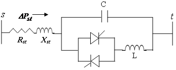 | Figure 1. TCSC module between node s and t |
 | (6) |
 | (7) |
 | (8) |
 from (1-(3), the overall system matrix for an m-machine system can be obtained as
  | (9) |
 ,
, 
 and
and  with
with  and
and  .Therefore, linearized state-space model of the multimachine system with TCSC controller can be expressed as
 | (10) |
 | (11) |
3. Description of the Test System
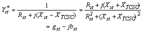
- The power system under consideration (Figure. 2) is one of the largest power network of Eastern India. It is a 14 area, 24 machine system consisting of 203 buses with 266 branches. It has 108 numbers of 132 kV lines, 30 numbers of 220 kV lines, 15 numbers of 400 kV lines and 6 numbers of 66 kV lines. The whole network includes 35 numbers of 3-windings line transformers and 37 numbers of 2-windings load transformers. There are 6 numbers of generators (#1, #2, #3, #5, #17 and #20) having higher capacity (540 MW-600 MW) while 8 numbers of generators (#4, #6, #7, #10, #11, #12, #13 and #19) are having medium capacity (150 MW-380 MW) and rest 10 numbers are of low capacity (20 MW-90 MW). The machines are modelled with four field windings on the rotor, one damper in the d-axis and two dampers in the q-axis. All machines are assumed to be equipped with IEEE Type –I excitation system and speed-input single stage power system stabilizers to ensure adequate damping of local modes. All the loads are assumed to be of constant power type. The nodal voltage magnitudes and angles are obtained in the simulation by the conventional N-R load flow.
 | Figure 2. Part of the 14 area, 24 machine and 203 bus study system with TCSC controller |
4. Synchronized Speed Phasor Measurement Unit (SSPMU)
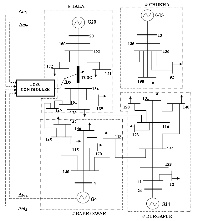
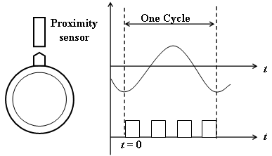
- In synchronized phasor measurement technology, by synchronizing the sampling processes for different signals which may be hundreds of miles apart, it is possible to put their phasors on the same phasor diagram. Figure. 3 shows a functional block diagram of typical Synchronized Speed Phasor Measuring Unit (SSPMU). The digital speed signals derived from the Proximity Sensor (PS) (Figure 4) are applied to the SSPMU which used synchronization signals from the GPS satellite system. The received GPS signals are converted to a suitable Intermediate frequency (IF) in the front end of the receiver, and then processed by microprocessor. The GPS receiver provides the 1 pulse-per-second (pps) signal and a time tag, which consists of the year, day, hour, minute, and second. The l-pps signal is usually divided by a phase-locked oscillator into the required number of pulses per second for sampling of the analog signals. The microprocessor determines the positive sequence phasors according to the recursive algorithm[18], and the timing message from the GPS. The computed string of phasors, one for each of the positive sequence measurements, is assembled in a Phasor data concentrator (PDC) and this data stream from PDC is then transmitted over a dedicated communication line through the modems[19]. A 4800 or 9600 baud communication line can support the transmission of the phasor stream at the rate of about every 2-5 cycles (40 – 100 msec) of the fundamental frequency (50 Hz), depending upon the number of positive sequence phasors being transmitted. Considering that the usual power system dynamic phenomena fall in the range of 0.2-2.5 Hz, it is possible to observe in real-time the power system dynamic phenomena with high fidelity at the control centre.
 | Figure 3. Synchronized Speed Phasor Measurement Unit (SSPMU) |
 | Figure 4. Configuration of proximity sensor |
 | (12) |
5. Mixed-Sensitivity Based Robust Controller Design: an LMI Approach
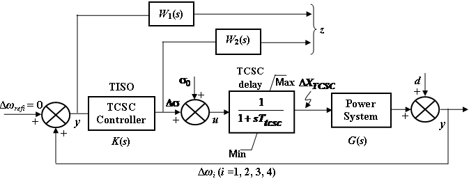
- The design objective in this section is to find an internally stabilizing damping controller that satisfies an infinity norm constraint, while ensuring that the closed-loop poles lie in certain locations in the complex plane. The closed- loop system together with the H∞ controller based on the standard mixed-sensitivity problem is proposed in Figure 5. In this figure G(s) is the open-loop plant, K(s) is the controller to be designed, and W1(s) and W2(s) are weights for shaping the characteristics of the closed-loop plant. The input signal to the controller is the normalized speed deviation (
 ), and output signal is the deviation in thyristor conduction angle (
 ).The state space description of the augmented plant is represented by[20]
 | (13) |
 | (14) |
 | (15) |
 is the state vector of the plant G(s), u is the plant input, y is the measured signal modulated by the disturbance input d and z is the controlled output. The controller K(s) can be realized by the following state space equations
 | (16) |
 | (17) |
 | (18) |
 | (19) |
 | Figure 5. The closed-loop system with mixed-sensitivity based H∞ controller |
 ,
,  ;
; ;
; ;
; . Without loss of generality, Dp22 can be set to zero to make the derivation simpler and the plant becomes strictly proper. The transfer function between ‘d’ to ‘z’ can be described as
 | (20) |
 | (21) |
 such that the bounded real lema[22] given by
  | (22) |
 | (23) |
 | (24) |

 | Figure 6. LMI region of closed loop poles |
 ;
; ;
;  where
where 

 and
and  The new controller variables are then defined as
 | (25) |
 | (26) |
 | (27) |
 | (28) |
 ,
,  ,
,  and
and  are solved form the LMIs employing interior-point optimization methods[25]. Once
 ,
, ,
, and
and are obtained the controller variables
 ,
,  ,
,  and
and are recovered by solving (25)-(28).
5.1. Design of Robust Damping Controller
- The LMI formulations described in Section 5 is now applied to the 14 area, 24 machine study system. Here an H∞ FISO controller was designed for the TCSC using four stabilizing signals (
 ) from four different remote locations (Figure. 2). The original system has a total of 193 states including one state for the TCSC delay. The corresponding LMI based controller would be of a higher order than this. The plant model is hence reduced to a 10-th order equivalent using square-root balanced truncation technique[21]. Following the standard guidelines of mixed-sensitivity design, weights W1(s) and W2 (s) are chosen as low and high pass filters, respectively.The weights W1(s) and W2 (s) are worked out to be:
 ;
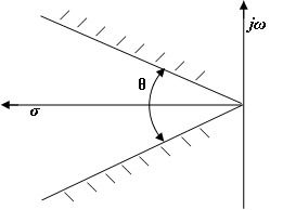
;  The multiobjective H∞ synthesis program for disturbance rejection and control effort optimization feature of LMI was accessed by suitably chosen arguments of the function hinfmix of the LMI Toolbox in MATLAB. The pole placement objective in LMI has been achieved by defining the conical sector with
  , which provides a desired minimum damping
  for all the closed-loop poles. The order of the controller obtained from the LMI solution was equal to the reduced plant order plus the order of the weights, which was quite high posing difficulty in practical implementation. Therefore, the controller was reduced to a seventh-order one by the balanced truncation without significantly affecting the frequency response. The state variable representation of the three-input, one-output controller for the TCSC is given in the Appendix A.2. This reduced-order controller has been tested on the full order system against varying generation, load power change and transmission line outage.
5.2. Robust Performance Evaluation of the WAM Controller
- The performance of the controller is evaluated here in the face of wide variations of system disturbances; that include real and reactive load increase (70 % more than nominal) in selected buses, drop in real power generations (Total 40 %) in some designated generators buses and simultaneous tripping of three transmission lines (# 42-53, # 118-122 and # 145-149). The WAM TCSC controller provides very good damping characteristics in all these contingencies for the critical inter-area mode. The damping ratio of the critical inter-area mode without and with control action has been represented in Table 2.It is evident from Table 2 that simultaneous occurrence of three tie-lines outage pushes the critical inter-area mode to the right half of the s-plane resulting instability for the system. In this situation installation of the WAM controller shows significant improvement of damping and brings back the system under stable operating condition establishing the need for the robust TCSC controller. The dynamic behaviour of the system also investigated against simulation time 10 sec. The angular speed response of machine #20 with different power system disturbances has been plotted in Fig. 7. It has been observed that the designed LMI based WAM TCSC controller imparted acceptable settling time for wide variation of disturbances.
| |||||||||||||||||||||||||||
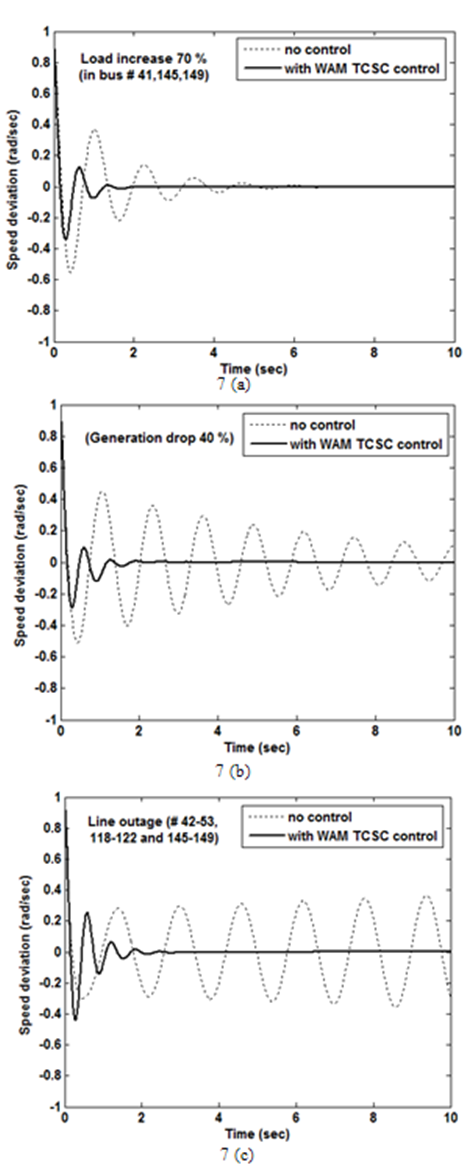 | Figure 7. Large disturbance dynamic response of machine # 20 (a) Load increase (b) Generation drop (c) Line outage |
6. Closed-loop Control Scheme of Inter-area Oscillations
- The objective in this section is to develop a closed-loop control system model using WAM based TCSC controller for mitigation of inter-area oscillations in the proposed study system. The proposed possible schematic diagram of smart WAM control system has been depicted in a block diagram (Figure. 8). Such a flexible control system will enable the wide area network to monitor and control their operations with higher degrees of efficiency and reliability. The sensing and measurement mechanism of remote substations variables (Δω) are assumed to be based on SPM with Global Position Satellite System (GPS) technology. To accomplish this, the transmission system needs to install four numbers of SSPMU for collection of rotor speed data corresponding to the machines (#4, #13, #24 and #20) located in four different areas or substations. Generator speed signals measured by the Proximity Sensor (PS) and Synchronized Speed Phasor Measuring Units (SSPMU) are transmitted via wide area communication network to the WAM controller. The controller produces stabilizing output signal, thyristor conduction angle () which introduces additional damping to the inter-area mode against said power system disturbances.
7. Conclusions
- In this paper the design of a mixed-sensitivity based H∞ controller in LMI framework is proposed for robust damping of a critical inter-area swing mode of a real multimachine power network. The salient contributions of this paper are highlighted as follows:This research work establishing the need of robust TCSC controller for wide area control of inter-area oscillations employing synchronized input signals.The concept of Synchronized Speed Phasor Measuring (SSPM) technology using GPS signal has been introduced in order to access remote stabilizing signal and centralize control of inter-area oscillations which can overcome the problem of transportation delay in wide area measurement.A smart feedback control scheme has been proposed for application of this designed wide area controller in order to realize the existing power system control into intelligent control system.The proposed technique can be implemented for the design of other WAM based FACTS controllers in addition with SPM technology for any multimachine power system.
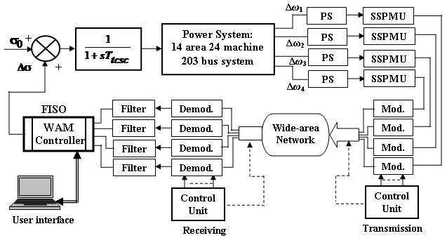 | Figure 8. Configuration of WAM based feedback control scheme |
Appendix A
A.1 Parameters of PSS and TCSC Module
 (Gain) = 10;
  (Lead time) = 0.4 sec;
  (Lag time) = 0.15 sec; XL (TCSC) = 0.000526 pu;XC (TCSC) = 0.00526 pu; XTCSC = ̶ 0.0130 pu ;Firing angle (
 ) = 155 deg.;
  (TCSC delay) =17 ms.
A.2 LMI based FISO TCSC controller
- The state-space representation of the four-input, single-output WAM controller for the TCSC


References
| [1] | Kundur P., Power System Stability and Control. McGraw- Hill: New York, 1994 |
| [2] | Kundur P, Klein M, and Rogers G.j., and Zywno M. S., 1989, Application of power system stabilizers for enhancement of overall system stability, IEEE Trans. on Power Systems, 4(2), 614-626 |
| [3] | Pandey R. K, and Singha N. K., 2009, UPFC control parameter identification for effective power oscillation damping, International Journal of Electrical Power and Energy Systems 31(6), 269-276 |
| [4] | Hingorani N. G, and Gyugyi L., Understanding FACTS: Concepts and Technology of Flexible AC Transmission System. IEEE Press: 2000 |
| [5] | Hassan M. O., Zakaria Z. A, and Cheng S. J., 2009, Impact of TCSC on enhancing power system stability, IEEE Power and Energy Conference, APPEEC, 1-6 |
| [6] | Pal B. C., Coonick A. A., Jaimoukha I. M., and El-Zobaidi H. A, 2000, Linear matrix inequality approach to robust damping control design in power systems with superconducting magnetic energy storage device, IEEE Transactions on power systems, 15(1), 356-362 |
| [7] | Chaudhuri B., and Pal B. C., 2004, Robust damping of multiple swing modes employing global stabilizing signals with a TCSC, IEEE Transactions on power systems, 19(1), 499-506 |
| [8] | Majumder R, Chaudhuri B, Pal B. C., 2007, Implementation and test results of a wide-area measurement-based controller for damping interarea oscillations considering signal-transmission delay, IET Gener. Transm. Distrib., 1(1), 1-7 |
| [9] | Ray S., and Venayagamoorthy G. K., 2008, Real-time implementation of a measurement-based adaptive wide-area control system considering communication delays, IET Gener. Transm. Distrib, 2(1), 62–70 |
| [10] | Juanjuan W., Chuang Fu, and Yao Z., 2011, Design of WAMS based multiple HVDC damping control system, IEEE Transactions on smart grid, 2 (2), 363-374 |
| [11] | Kamwa I., Grondin R., and Hebert Y., 2001, Wide-area measurement based stabilizing control of large power systems—A decentralized/hierarchical approach. IEEE Trans. Power Syst., 16(1), 136–153 |
| [12] | Ree La J. D., Centeno V., Thorp J. S., and Phadke A. G., 2011, Synchronized phasor measurement applications in power systems, IEEE Transactions on smart grid, 1(1), 20-27 |
| [13] | Heydt G., Liu C., Phadke A., and Vittal V., 2001, Solutions for the crisis in electric power supply, IEEE Comput. Appl. Power, 14(3), 22–30 |
| [14] | Okou F, Dessaint L. A., and Akhrif O., 2005, Power system stability enhancement using a wide-area signals based hierarchical controller. IEEE Trans. on Power System, 20(3), 1465-1477 |
| [15] | Cvetkovic M, and Ilic M., 2011, PMU based transient stabilization using FACTS, IEEE Power Systems Conference and Expositions (PSCE), Phoenix, AZ, 1-6 |
| [16] | Sauer P. W., and Pai M. A., Power System Dynamics and Stability. Pearson Education Pte. Ltd.: Singapore, 1998 |
| [17] | Fuerte-Esquivel C. R., Acha E., and Ambriz-Pe'rez H., 2000, A thyristor controlled series compensator model for the power flow solution of practical power networks, IEEE Trans. on power systems, 15(1), 58-64 |
| [18] | Phadke A. G., and Thorp J. S., Synchronized Phasor Measurements and Their Applications, Springer: New York, 2008 |
| [19] | Bose A., 2010, Smart transmission grid applications and their supporting infrastructure, IEEE Transactions on smart grid, 1(1), 10-19 |
| [20] | Skogestad S., and Postlethwaite I., Multivariale Feedback Control Analysis and Design. John Wiley and Sons: 1996 |
| [21] | Zhou K., Doyle J., and Glover K., Robust and Optimal Control. Prentice Hall: 1995 |
| [22] | Gahinet P., and Apkarian P. A., 1994, Linear matrix inequality approach to H∞ control. International Journal Robust Nonlinear Control, 4(4), 421–448 |
| [23] | Chilali M., and Gahinet P., 1996, H∞ design with pole placement constraints: An LMI approach, IEEE Transaction on Automatic Control, 41(3), 358-367 |
| [24] | Scherer C., Gahinet P., and Chilali M., 1997, Multiobjective output-feedback control via LMI optimization, IEEE Trans. on Automatic Control, 42(7), 896-911 |
| [25] | Nesterov Y., and Nemirovski A., Interior Point Polynomial Methods in Convex Programming; Theory and Applications. PA, SIAM: Philadelphia, 1994 |