Mihailescu Calin , Florin Rezmerita , Calomfirescu Ileana , Mihai Iordache , Nicolae Galan
Electrical Engineering Faculty, Politehnica University of Bucharest, Bucharest, Postcode 060026, Romania
Correspondence to: Florin Rezmerita , Electrical Engineering Faculty, Politehnica University of Bucharest, Bucharest, Postcode 060026, Romania.
| Email: |  |
Copyright © 2012 Scientific & Academic Publishing. All Rights Reserved.
Abstract
The rotor parameters, the resistance and the leakage inductance, vary with the currents frequency of rotor bars due to skin effect, and for small frequencies can be negligible (under 10 15 Hz); but for higher frequencies this variation of the parameters cannot be negligible. In this paper, for higher frequencies some analytic expressions are proposed, that result from the skin effect theory, for the rotor resistance and for the leakage inductance. The simulations were done by SYMNAP – SYmbolic Modified Nodal Analysis Program, a program that can determine, in a full-symbolic form the voltages and the currents for the equivalent scheme for one phase of the asynchronous motor. Symbolic expressions for the characteristics quantities of the general regime of the induction motor allow graphic representation for different parameters. These analytic expressions allows a more accurate analysis of asynchronous motor performance for different drive systems. To simulate the dynamic (transient) behavior of the induction motor, Park-Blondel equations have been used; these equations have a nonlinear form due to both their structure and frequency variation of the rotor parameters. The integration of these equations is performed with the help of the integration routines for ordinary differential equations in Matlab programming environment. It was found that the nominal values of the quantities that characterize the induction motor operation, obtained by simulation, practically coincide with the values from the catalogue.
Keywords:
Induction Motor, State Equations, Transient Behavior, Deep Rotor Bars
1. Introduction
Numerous studies have been made on estimating the electrical parameters of the asynchronous machine given both skin effect, and the saturation level[1-9]. For the electrical drives with three phase induction motors with deep rotor bars were developed mathematical models and command strategies for developing high performance systems[6]. In electrical drives it is preferred the vector command in respect to the rotor flux, a flux that cannot be defined using one form for motor with deep rotor bars; as a result, in many cases it is used the air gap flux for the vector command. Using the pseudorotor-flux, it can be achieved similar performances as with the rotor flux orientation, in this case, the equivalent rotor parameters are used. The squirrel cage with deep rotor bars can be equivalent with a double cage, one of these cages having constant parameters [8].Based on the influence of the skin effect over electrical rotor parameters can be constructed a mathematical model for the asynchronous motor with deep rotor bars that allows simulation of different operating modes are presented in this paper. It is considered constant stator current frequency, equal to the network frequency at which the motor is fed. Rotor parameters are considered constant, independent of the rotor current frequency, for values between 0 and 10...15 Hz. For higher frequencies, analytic expressions are proposed, that result from the skin effect theory, for the rotor resistance and leakage inductance. In sinusoidal steady-state, simulations were performed by the SYMNAP – SYmbolic Modified Nodal Analysis[10], a program that allows complete symbolic determination of the branch voltages and currents of the equivalent scheme corresponding to one phase of the induction motor. In order to simulate the induction motor in the transient (dynamic) behaviour we use the Park-Blondel equations. These equations have a nonlinear form due to both their structure and the variation of the rotor parameters in respect of the frequency. The integration of these equations is performed with the help of the integration routines for ordinary differential equations in Matlab programming environment.
2. The Mathematical Model of the Induction Motor
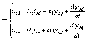
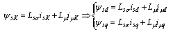
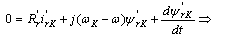
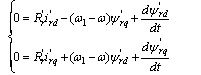
The mathematical model of the induction motor used for any behaviors is elaborated in synchronous coordinate (Park-Blondel equations) and is presented as it follows: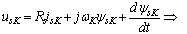 | (1a) |
 | (1b) |
 | (1c) |
 | (1d) |
 | (1e) |
 | (1f) |
 | (1g) |
 | (1h) |
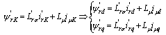
The general coordinate system K, which has the angular velocity ωK in respect to the stator coordinate system, is particularized for the synchronous coordinate with speed ω1, this means that ωK = ω1.In the system equations (1) the rotor cage parameters  and
and  dependent on the rotor bars angular frequency ωr, and the others electrical parameters are constants. If the simulations are performed for only one stator frequency (such as nominal stator frequency) the parameters
  and
and  vary with the slip s. For simulations at different stator frequencies is absolutely necessary that the rotor parameters are function of the angular frequency of the currents from the rotor bars ωr, (for the stator frequency of f1 = 5 Hz, and s = 1, the influence of the skin effect is negligible, that means the dependence on the slip s is not relevant).
2.1. Rotor Electrical Parameters
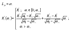
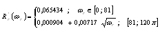
The skin effect analysis shows that the rotor resistance  reported at the stator increases with
 , and leakage inductance
  decreases with
 . Therefore, the rotor parameters reported at the stator can be written as it follows:
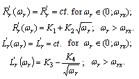 | (2) |
The constants K1, K2, K3 and K4 are determined from the continuity condition at the point ωr = ωrx and calculation of the electrical parameters for the squirrel cage at starting point (s = 1), these parameters are obtained from the catalogue data. Till the pulsation is ωr = ωrx, the rotor parameters are considered constant, and for ωr ≥ ωrx the rotor parameters vary with pulsation ωr according to relations (2). These are valid for a wide range of frequency from rotor circuit.
2.1.1. Rotor Parameters at Starting
Rotor squirrel cage is made with deep bars, parameters  and
and  vary in large limits when the rotor angular frequency ωr takes values between 0 and ω1; at the starting (n= 0), the rotor angular frequency ωr is equal to the stator angular frequency ω1, in this case the skin effect is strong (ω1 = 2·π·60).The catalogue data for the analysed induction motor are presented in table 1 with the known notations.
| Table 1. The Catalogue data for the Motor |
| | Pn [kW] | Un [V] | In [A] | n1 [rot/min] | N [rot/min] | ηn [%] | | cosφ1n - | ip - | mp - | mm - | J [kgm2] | Star connection |
|
|
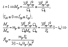
Based on these data the following quantities can be calculated: P1n, sn, Mn, Sn. Next step for the calculation of the starting parameters is: the starting impedance Zp, the rotor resistance at starting point  and the leakage inductance at staring point
  . In the computation process the rated impedance Zn is used. Using the known relations from the asynchronous motor theory, for n = 0, the rotor resistance
  is computed, thus:
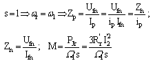 | (3a) |
 | (3b) |
The values of the parameters Zp, Rs, Lsσ, are known and the leakage inductance
  can be calculated, at staring point, with the following relation:
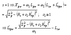 | (4) |
At this stage, in the absence of the skin effect the parameters  and
and are known and if skin effect is taken into account we will use the parameters
  . The calculation of the K1, K2, K3 and K4 constants leads to the next relations for
  .
. | (5a) |
 | (5b) |
The last two relations in system (5) highlight the variation of the rotor parameters  and
and  in respect of the ωr, due to skin effect. The mathematical structure of the model (1), remains the same, except that the parameters
  and
and  become
 , and
, and , respectively, according to relation (5).For the relative rotor resistance reported to the stator
  is known relationship that rotor resistance in relative unit
  is equal to the rated slip sn as shown in the following relations:
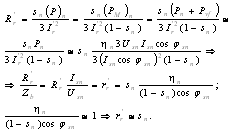 | (6) |
2.2. The Study of Asynchronous Three Phase Motor with Known Parameters
In order to simulate different operating behaviors of the three phase asynchronous motor expressions obtained in section 2.1 we will use the rated values presented in table 2:| Table 2. Rated Values for the Motor |
| | Pn [kW] | Un [V] | In [A] | n1 [rpm] | N [rpm] | ηn [%] | | 100 | 560 | 130 | 1200 | 1168,8 | 0,897 | | cosφ1n - | ip - | mp - | mm - | J [kgm2] | Connect. | | 0,87 | 4 | 1,1 | 1,8 | 3,38 | star |
|
|
Ufn=323,32 V; Ifn=130 A; Zb =Zn=Ufn/Ifn=2,48 Ω ; fn=60 Hz ; p=3; Rs=0,053 Ω ;  =0,0657 Ω ; Lsσ =1,034 mH;
  =0,955 mH ; Lμ =28,1 mH .With the values from table 2 the next quantities are calculated: Mn = 817 Nm; Mp = 898,7 Nm; Ip = 520 A; Sn = 128094,8 VA; sn =0,026; P1n = Sn·cosφ1n = 111442,5 W;
  =0,0262 ≅ sn = 0,026.It can be noticed that the last relation (6) is verified with a very good approximation. Based on relations (5) and the data in table 2 are obtained the numerical values for the electrical parameters reported to the rotor cage for ωrx = 81 rad/s; electrical parameters of the motor are:
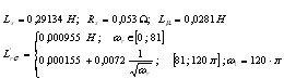 | (7a) |
 | (7b) |
The rotor cyclic inductance is expressed as: 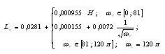 | (8) |
With these data we can make any simulation for the motor in any working behavior.The variations of the parameters  and
and  in respect of the rotor angular frequency ωr are presented in figures 1 and 2.
 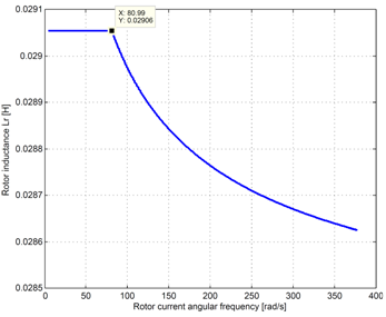 | Figure 1. Rotor leakage inductamce  variation depending on the pulsation ωr. variation depending on the pulsation ωr. |
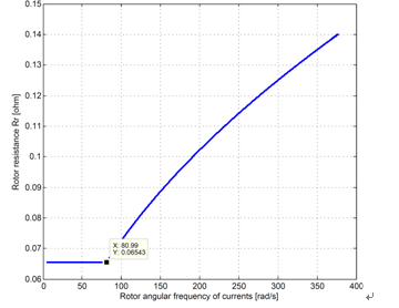 | Figure 2. Rotor resistance variation depending on the pulsation ωr. variation depending on the pulsation ωr. |
For motor with the data sheet from table 2, the time constants are: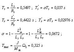 | (9) |
where: Ts – is the time constant of the stator winding;  – represents the transient time constant of the stator winding; Tr – is the time constant of the rotor winding;
  – is the transient time constant for the rotor winding, and
  is the mechanical constant of the motor. The stator time constants are greater than the rotor time constants. Therefore, the transient behavior in the stator winding will take more time than the transient behavior in the rotor windings.
3. Resisting Torque at the Motor Shaft
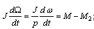
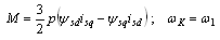
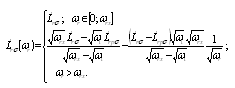
Load torque is required by the drive equipment (working machine) for a technological operation (turning a piece, forming by pressing, lifting an object) or other operations such as electric traction.Mechanical friction torques exists, both in electrical machine, and in working machine. It is customary that all torques that work in the opposite direction in the electrical machine–working machine system, distinct from the electromagnetic torque developed by motor, to be summed into one resultant load torque, which is called a resisting torque, a torque that is opposing the movement. The electrical motor develops a torque M2 at shaft which gives a stronger movement then Mr; in steady-state Mr = M2. Mechanical characteristic of the driven system represents the dependence between the load torque (resistance) Mr at the drive system shaft and a quantity which characterizes the driven installation (the angular velocity Ω, the position angle α, the covered space etc.). In many cases the mechanical characteristic is presented as: Ω = f(Ms).An analytic expression for the mechanical characteristic can be the following expression:  | (10a) |
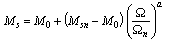 | (10b) |
where:  – the rated angular velocity;
  – the initial resisting torque;
  – the rated load torque; a – an exponent which can take different values , for example: a = 0
  =constant (lifting mechanism); a=1→ Ms linear variation with the angular velocity Ω (braking with a dc machine with constant excitation); a=2→mechanical parabolic characteristic, often encountered in practice.In railway traction, the load torque is based on the variation of traction force F0 at the wheel rim in respect of the locomotive speed (figure 3), to which is added the dependent drag resistance RL (figure 4) function of velocity variation.
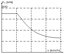 | Figure 3. Variation of the drive force F0 at the wheel rim according to the movement speed of the locomotive |
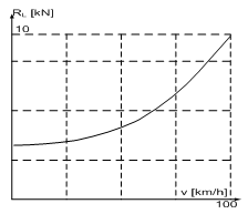 | Figure 4. Variation of the RL drags resistance depending on the speed of the locomotive |
It is noted that RLF0; and on this basis Mr torque at motor shaft can be approximated as shown in Figure 5.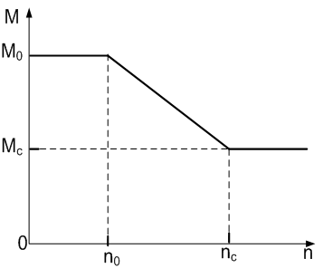 | Figure 5. Variation of the resistive torque Mr at the motor shaft, function of the rotor speed n |
4. Simulations
4.1. Simulation of the Starting Process with General Mathematical Model for Rated Data and Constant Rotor Parameters
These simulations are preformed for stator currents iA, iB, iC, for rotor speed and electromagnetic torque. These simulations are performed at rated data for a resisting torque equal to the electromagnetic torque and variable rotor parameters. The induction motor can start at rated torque due to the skin effect which increases rotor resistance and the starting torque. The results of the simulations are presented in figures 6, 7, 8 and 9.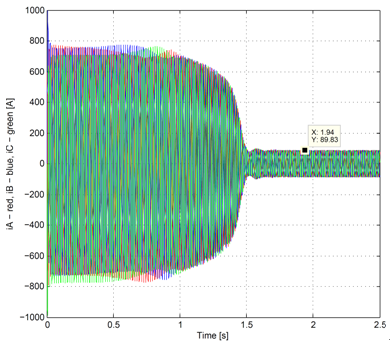 | Figure 6. The stator currents iA, iB, iC function of time |
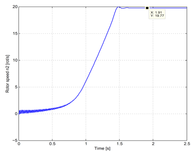 | Figure 7. The rotor speed function of time |
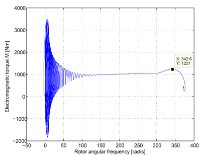 | Figure 8. The electromagnetic torque function of ω = pΩ |
The results are similar to those in the literature; at starting point appears that the stator current have high amplitude, and the torque has a greater value than the rated torque, because of the skin effect. Note that the transient process for the stator currents has a longer variation due to the rotor parameters variation with the changing speed. The transient behavior has two steps: the first step is at time t=0 till tI≅1,3s when the rotor parameters vary in respect to the rotor current angular frequency (figure 6 and figure 7), this variation is maintained almost till the operating speed; the second step takes place for the constant rotor parameters and it is between tI≅1,3s la tII≅1,5s (figure 6). For the first step the transient behavior is not changed significantly since the rotor parameters vary continuously and in tight limits. The rotor speed is essentially determined by the motion equation in which the inertial moment J occurs, and only at large oscillations for the amplitude of the electromagnetic torque (figure 8) the speed has small swinging amplitude (figure 7, t < 0,9 s ). The electrical transient process takes longer than the mechanical transient process.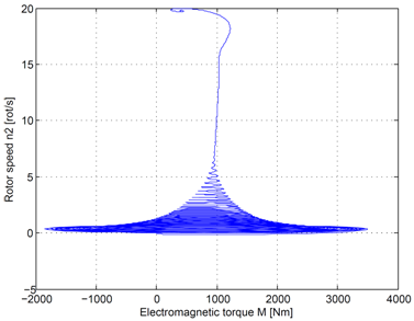 | Figure 9. Mechanical characteristic the rotor speed in function of the electromagnetic torque |
4.2. Results
The motor has the following parameters:f1=60 Hz, J=60 kgm2 and U1=U1n=323,32 V.According to the analysis presented in section 3, the load torque at starting point for the locomotive depending on the speed it presents in figure 10; initial torque value is 800 Nm, then decreases linearly to the value of 400 Nm.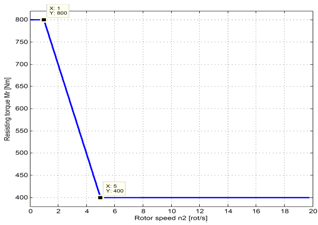 | Figure 10. Variations of the load torque in respect of the locomotive speed |
The motor that drives an electric locomotive works at a higher equivalent inertial moment; total inertial moment Jt from the motion equations is computed with the expression: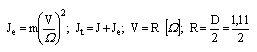 | (11) |
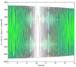
Where: m is the mass of the train which is for one motor, V is the train speed and Ω is the angular velocity of the motor shaft. Mechanical time constant are much greater than the electrical time constants, therefore, permanent regime is dominant.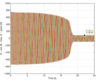 | Figure 11. The time variation of the stator currents |
 | Figure 12. The time variation of rotor currents |
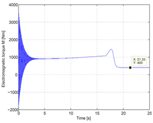 | Figure 13. The time variation of the electromagnetic torque |
As expected, at a high inertial moment J, transient time is longer because rotor parameters vary slowly as the rotor speed varies. The stator current magnitude (figure 11), and rotor currents (figure 12) are all bellow 800 A, smaller for low inertial moment J case.It is found that variation of the electromagnetic torque from the first part of the transient behavior (figure 13) does not make swings for the rotors speed (figure 14).The transient behavior of the stator currents is longer than the one of the rotor currents because the time constants for the stator windings are bigger than the ones of the rotor windings. The linear decrease of the resisting torque Mr leads to a pronounced perturbation of the rotor currents in variation time interval: 9…11s because with the variation of the resisting torque, the electromagnetic torque (depending on the rotor quantities) also varies directly (figure 12). The resisting torque variations influences less the stator currents because of the inductive coupling between the two armature windings, (figure 11).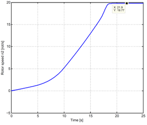 | Figure 14. The time variation of the rotor speed |
5. Conclusions
This paper presents the influence of skin effect on the electrical parameters of the rotor and on this basis is constructed the mathematical model of the asynchronous machine with deep bars that allows simulation of different operating behaviors. Initial, the stator currents frequency is considered constant, equal to the network frequency. In fact, rotor parameters are considered constant, independently of the rotor frequency, for rotor frequency values between 0 and 10...15 Hz. For higher frequencies analytic expressions are proposed, resulting from skin effect theory, both for the rotor resistance and the leakage inductance. The asynchronous motor simulations in sinusoidal steady state, were performed with the program the SYMNAP – SYmbolic Modified Nodal Analysis, a program that can determine in a full- symbolic form the voltages and the currents for the equivalent scheme for one phase of the asynchronous motor. Symbolic expressions for the characteristics quantities of the general regime of the induction motor allow graphic representation for different parameters.In simulation of dynamic (transient) behavior of the induction motor, Park-Blondel equations have been used; these equations have a nonlinear form due to both their structure and frequency variation of the rotor parameters. The integration of these equations is performed with the help of the integration routines for ordinary differential equations in Matlab programming environment.Note that the transient process for the stator currents has a longer variation due to the rotor parameters variation with the changing speed. The transient behavior has two steps: the first step is when the rotor parameters vary in respect to the pulsating currents from the rotor circuit, this variation is maintained almost till the operating speed; the second step takes place for the constant rotor parameters and transient behavior, which are carried out similar to inductive circuits. For the first step the transient behavior is not changed significantly since the rotor parameters vary continuously and in tight limits.At large oscillations of the electromagnetic torque amplitude, the speed has small swinging magnitude. The electrical transient process takes longer than the mechanical transient process.
ACKNOWLEDGEMENTS
The work has been co-funded by the Sectoral Operational Programme Human Resources Development 2007-2013 of the Romanian Ministry of Labor, Family and Social Protection through the Financial Agreement Posdru/88 /1.5/s/61178 AND Posdru/107/1.5/s/76909.
References
| [1] | A.-K. Repo, P. Rasilo, a. A. Arkkio, Dynamic electromagnetic torque model and parameter estimation for a deep-bar induction machine, IET Electr. Power Appl., vol. 2, No. 3, pp. 183 -192, 2008 |
| [2] | Levi E., Main flux saturation modelling in double-cage and deep-bar induction machines, IEEE Trans. Energy Conversion, vol. 11, No. 2, pp.305 – 311, 1996 |
| [3] | K.S. Huang, Q.H. Wu, D.R. Turner, Effective Identification of Induction Motor Parameters Based on Fewer Measurements. IEEE Trans. Energy Converssion, vol. 17, No. 1, pp.305 – 311, pp. 55 – 59, 2002 |
| [4] | D.J.Atkinson, J.W. Finch, P.P.Acarnley, Estimation of rotor resistance in induction motors, IEE Proc. Electr. Power Appl., vol. 143, no.1, pp. 87 -94, 1996 |
| [5] | J. Pedra, L Sainz, Parameter estimation of squirrel-cage induction motors without torque measurements, IEE Proc. Electr. Power Appl., vol. 153, no.2, pp. 87 -94, 2006 |
| [6] | Rik W.A.A. De Doncker, Field-Oriented Controllers with Rotor Deep Bar Compensation Circuits, IEEE Trans. Industry Applications, vol. 28, nr. 5 , pp. 1062 – 1070, 1992 |
| [7] | Aurel Câmpeanu, Introducere în Dinamica Maşinilor Electrice de Curent Alternativ, Editura Academiei, Bucureşti, 1998 |
| [8] | Jul-Ki Seok, Seung-Ki Sul, Pseudorotor-Flux-Oriented Control of an Induction Machine for Deep-Bar-Effect Compensation, IEEE Trans. Industry Applications, vol. 34, nr. 3 , pp. 429 – 434 1998 |
| [9] | Alexander C. Smith, Russell C. Healez, Stephen Williamson, A Transient Induction Motor Model Including Saturation and Deep Bar Effect, IEEE Trans. Energy Converssion, vol. 11, No. 1, pp.8 -15, 1996 |
| [10] | M. Iordache, Lucia Dumitriu, SYMNAP – SYmbolic Modified Nodal Analysis, User Guide, Library of Electrical Department, PUB, Bucharest, 2000 |
 Abstract
 Reference
 Full-Text PDF
 Full-Text HTML