Alexander G. Yushchenko , Dovlet B. Mamedov
National Technical University “Kharkiv Polytechnic Institute”, Ulitsa Frunze 21, Kharkov, 61002, Ukraine
Correspondence to: Alexander G. Yushchenko , National Technical University “Kharkiv Polytechnic Institute”, Ulitsa Frunze 21, Kharkov, 61002, Ukraine.
| Email: |  |
Copyright © 2012 Scientific & Academic Publishing. All Rights Reserved.
Abstract
The article presents the results of comparative analysis of WDR and microstrip-based resonator filters regarding their electrical parameters and overall dimensions. For alternative WDR filters design, we use a method of intellectual synthesis of a band pass filter structure which is based on formalized knowledge about the physics of coupled resonators. The basic idea of the expert system created consists in physical analysis of signals passing through the filter, which is performed on the basis of a known solution for electrodynamic problem of scattering of fundamental electromagnetic waves in a multi-tier structure. The comparative analysis is conducted in a wide frequency range of 3 – 70 GHz. We show that the advantage of WDR filters consists in selective properties and discuss the ways of their adaptation to planar technologies. It was demonstrated that electrodynamic properties of WDR filters allow creating devices ranging from narrow to ultra wide passbands. Finally, it was emphasized that a combination of superconducting materials and sapphire or quartz resonators is also very promising for developing WDR-based filters with unique selective properties.
Keywords:
waveguide-dielectric filters, microstrip filters, comparative filter analysis, new generation telecommunications devices, millimeter waves, intellectual CAD
1. Introduction
Modern telecommunications wireless technology requires different types of band pass filters for selections and compactions of information channels. Among the known microwave filters, the designs based on leukosapphire and quartz partially filled waveguide-dielectric resonators (WDR) pleased into cut-off waveguides are distinguished due to their general quality parameters, such as high unloaded Q's, sparse spectrum of parasitic modes and usable level of transmitted power[1,2]. The partial filling by this high Q dielectric allows to increase to one order the unloaded Q of the resonator. Resonators partially filled in the waveguide H-plane, differ from E-plane ones in having a sparser spectrum of parasitic modes and somewhat lower unloaded Qs. Cross-shapes of the cut-off waveguide cross-sections enable to fix there E- and H-plane resonance size dielectric inserts by means of projections[3].Different systems of temperature compensation or temperature stabilization are used to compensate a temperature drift of filters frequency caused temperature dependence of crystals dielectric permittivity in the case of narrow bandwidths.Thermostable ceramics with high dielectric permittivity are used in the low-frequency of centimeter range that can significantly reduce the weight and size parameters of filters based on WDR. Usually such kind of filters are included directly into the waveguide main tract. Due to transition of a mobile communication up to the millimetre wave range it is necessary to work out compact high unloaded Qs filtering elements, therefore the adaptation of WDR filters to planar technologies is observed[4]. Due to the large variety of other filters designs, especially based on microstrip resonators, comparative analysis of both electric and size parameters is actual subject of this article.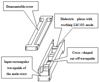 | Figure 1. The Three-tier Microwave Filter design with H-plane dielectric plates |
2. Key Design of WDR Filters and Its Intellectual CAD
Figure 1 shows key design of WDR filter with H-plane dielectric plates. The problem of scattering  on this structure wave was solved by the mode matching method[5].
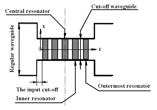 | Figure 2. Five-tier WDR Filters geometry |
To eliminate the influence of both the calculation error and manufacturing process, we provide adjusting screws symmetrically above each dielectric insert[2,3].The calculations were carried out for 30 wave types in a regular waveguide and one wave type in a cut-off waveguide [5]. The comparison of the computed and measured results shows that they are corresponded well enough even with so simple approximation: the errors are less than 1.5% in both cases, i.e. for frequency and insertions losses. The algorithm of approximate synthesis allowed us to reduce the time of development and obtain an acceptable filter response even after the first iteration.Designs of filters were calculated by modified intellectual CAD system[6]. On the basis of formalized physical knowledge about the behavior of coupled resonators, the original CAD system analyses electromagnetic signal passing through a filter structure and makes decisions gradually approaching the optimal filter design through a series of changes in its geometry. The efficiency of intellectual CAD depends only on the accuracy of the analysis problem solution and the exactness with which the application conditions of the rules applied match the data. Therefore it is high enough: the errors are less than 2% not only for frequency, but for insertions losses too. The results of intellectual CAD of WDR multi- tiered filters are given bellow. Filter sizes, based on WDR’s are shown in Tables (Appendix); descriptions are explained in Fig. 2.
3. Comparative Analysis of Different Types of Band Pass Filters
Figures 3 and 4 shows the comparative characteristics of the frequency response of filters based on WDR in three – and seven-tier embodiment and 6-pole high-temperature superconducting (HTS) microstrip bandpass filter which build for radio- astronomy applications[7].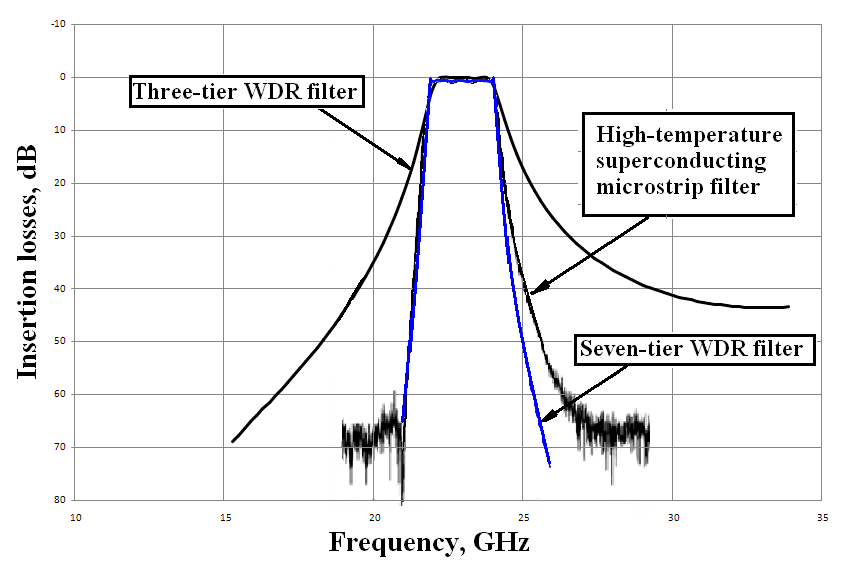 | Figure 3. Responses of the filters based on WDR and of High- Temperature Superconducting (HTS) Microstrip (at 70 K) |
Microstrip filter was built with using standard 0.5-mm- thick substrate for HTS thin film and has midband insertion loss of 0.11 dB with a ripple of 0.4 dB ((at 70 K). The typical filter size of 4.5 mm in width and 20 mm in length, of which the resonant system is 13.9 mm.Figures 3 and 4 shows that the three-tier WDR filter has a low steepness of slopes of frequency response, while a seven-tier has a much larger steepness of high-frequency slope and some smaller ripple in the passband. It seems that a combination of superconducting materials and sapphire resonators will allow to reach a record low losses in the passband of filters based on WDR.Figures 5 and 6 presents the comparative characteristics of the frequency response of filters based on WDR in three – and five-tier embodiment and broadband 70-GHz millimetre-wave RFIC-onchip bandpass filter using a 0.18-μm standard CMOS process[8]. 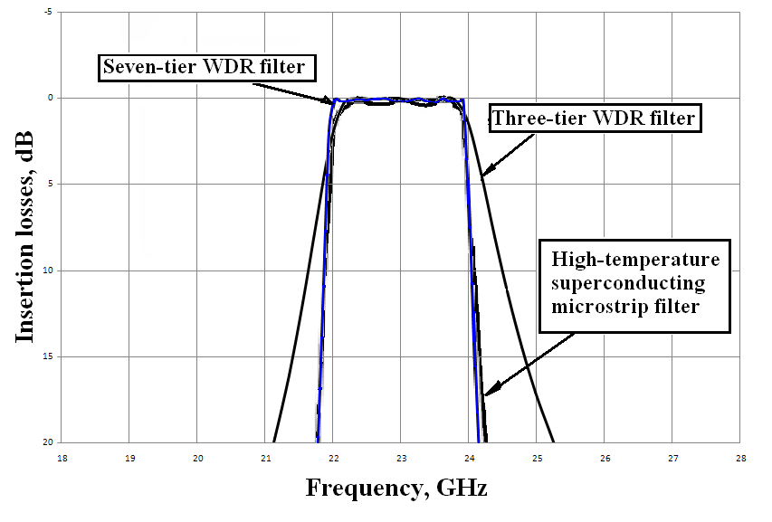 | Figure 4. Bandwidths of the Filters based on WDR and of High- Temperature Superconducting (HTS) Microstrip Bandpass Filter (at 70 K) |
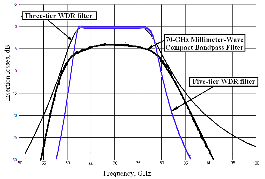 | Figure 5. Responses of the Filters based on WDR and the 70-GHz Millimetre-Wave Compact Bandpass Filter |
Bandpass filter consisting of planar ring resonator structure and its size is 650 x 670 um2. The filter bandwidth is about 18 GHz which has 3.6 dB of insertion losses. Filters sizes based on WDR, which have given bellow are shown in Table 1 and Table 2, respectively. Figures demonstrate that the three-tier WDR filter has a lower steepness of the high-frequency slope of response, while in five-tier embodiment it has a greater selectivity on both slopes and dramatically smaller losses in the passband in both cases. 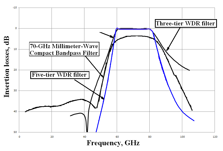 | Figure 6. Bandwidths of the filters based on WDR and the 70-GHz Millimetre-Wave Compact Bandpass Filter |
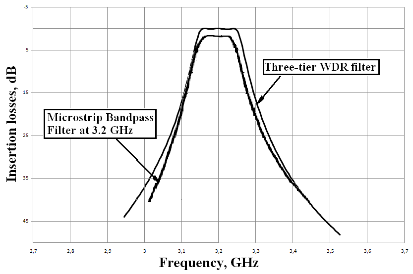 | Figure 7. Responses of the Filters based on WDR and Microstrip Band pass filter for the WiMAX application at the frequency 3.2 GHz |
Figure 7 presents the comparative characteristics of the frequency responses of filter based on WDR in three-links embodiment and microstrip bandpass filter for the WiMAX application at the frequency 3.2 GHz[9].Microstrip filter was built with using PCB with thickness 0.762 mm (0.03 inch). The substrate of type RO TMM10 has the relative permittivity of 9.2 and tangent loss of 0.0022, characteristic dimensions of the filter approximately are 8.7 mm in width and 56.2 mm in length. Filter made according to the calculations has insertion losses about 7.5 dB and smaller bandwidth of about 50 MHz, instead of 100 MHz.It appears that the discrepancy between estimated and actual results due to not «larger loss of the coaxial connectors and their poor contacts to the microstrip line»[9], but to low unloaded Q factor of microstrip resonators.Filter sizes based on WDR are shown in Table 1, it has comparable steepness of the characteristic even in the three-links embodiment and dramatically less losses in the passband.
4. Conclusions
Filters based on partially filled waveguide-dielectric resonators impressively surpass microstrip ones by selective properties, but concede it in cost and diminutiveness. Therefore the above-mentioned WDR filters can have the microstrip input \ output coupling elements and be adapted to plane technologies. It also has some perspectives to use quasi-  mode resonators because their frequencies do not depend on the height of waveguide screen. In this aspect they are attractive for creation of a new generation telecommunications devices of millimeter range waves.The WDR filters electrodynamics allows creating devices in a range from narrow to the ultra wide passbands. They are also very promising in a combination of superconducting materials and sapphire or quartz resonators, which will allow to develop filters based on WDR with unique selective properties.
Appendix
| Table 1. Three-tier WDR ffilter sizes |
| | three-tier WDR FILTER DESIGN PARAMETERS | Central Frequency, GHz | | 3.2 | 23 | 70 | | Width of the regular waveguide, mm | 72.00 | 11.00 | 3.60 | | Width of the cut-off waveguide, mm | 15.00 | 4.40 | 1.80 | | Waveguide height, mm | 35.00 | 5.50 | 1.80 | | Length of the input cut-off waveguide section, mm | 1.25 | 0.83 | 0.02 | | Length of the central resonator, mm | 1.65 | 0.94 | 0.31 | | Length of the outermost resonators, mm | 1.51 | 0.90 | 0.27 | | Filter length, mm | 42.00 | 12.47 | 2.64 | | Band pass, % | 6.25 | 8.69 | 23.40 | | Insertion Losses, dB | < 0.2 | < 0.2 | < 0.2 | | Dielectric permittivity of resonators | 80.0 | 11.6 | 9.2 |
|
|
Width and height of regular waveguide corresponds to the standards accepted in the former USSR and now are in force in Ukraine.| Table 2. Five – and Seven-tier WDR Filter sizes |
| | FIVE-tier WDR FILTER DESIGN PARAMETERS | Central Frequency GHz | SEVEN-tier WDR FILTER DESIGN PARAMETERS | Central Frequency, GHz | | 70 | | 23 | | Width of the regular waveguide, mm | 3.6 | Width of the regular waveguide, mm | 11.0 | | Width of the cut-off waveguide, mm | 1.79 | Width of the cut-off waveguide, mm | 4.4 | | Waveguide height, mm | 1.8 | Waveguide height, mm | 5.5 | | Length of the input cut-off waveguide section, mm | 0.02 | Length of the input cut-off waveguide section, mm | 0.9 | | Length of the central and inner resonators, mm | 0.33 | Length of the central and inner resonators, mm | 0.94 | | Length of the outermost resonators, mm | 0.27 | Length of the outermost resonators, mm | 0.89 | | Filter length, mm | 5.15 | Filter length, mm | 34.9 | | Band pass, % | 29 | Band pass, % | 7.3 | | Insertion Losses, dB | < 0.25 | Insertion Loss, dB | < 0.25 | | Dielectric permittivity | 9.2 | Dielectric permittivity | 11.6 |
|
|
References
| [1] | A.G. Yushchenko, “Waveguide-dielectric filters based on leukosapphire and quartz monocrystals”, SPI’s Int. Symp. on “Voice, Video and Data Communications”, Dallas, TX, USA, v. 3232, pp.73-79, 05 November 1997. |
| [2] | A.G. Yushchenko, “High unloaded-Qs WDR filters designing”, 2001, International Journal of Infrared and Millimeters Waves, vol.22, no.12, 1831-1836 |
| [3] | Patent of Russia Federation №2040080, “Microwave filter”, A. G. Yushchenko et al. Buluten Izobreteniy, July 20 1995. (In Russian). |
| [4] | Kazuhisa Sano, Meiji Miyashita, 1999, “Dielectric Waveguide Filter with Low Profile and Low-Insertion Loss” , IEEE MTT, V.47, No.12, 2299-2303, |
| [5] | M.E. Ilchenko, A.G. Yushchenko, S.F. Shibalkin, V.V. Popov, “ Waveguide-dielectric filters based on cross shaped waveguides”, Int. Conf. Millimeter and Submillimeter Waves and Applications, San Diego, vol. 2250, pp. 571-572 , 10-14 January 1994. |
| [6] | A. Yushchenko, D. Mamedov and D. Zaytsev, "Intellectual CAD for Three-Tier Wide Band WDR Filters," 2012, Wireless Engineering and Technology, vol. 3, no. 1, 30-35. |
| [7] | Gao L, Guo J, Wang Y H, et al., 2009, “A 23 GHz high-temperature superconducting microstrip filter for radio astronomy”. Chinese Sci Bull, 54: 3485―3488. |
| [8] | C.-Y. Hsu , Y.-S Lin , C.Y., Chen and H.-R. Chuang, “A 70-GHz Millimeter-Wave Compact Bandpass Filter Fabricated Using Standard 0.18-μm CMOS Technology” Proceedings of the 38th European Microwave Conference, pp.215-217, The Netherlands, from 27 to 31 October 2008. |
| [9] | M. Alaydrus, 2010, “Designing Microstrip Bandpass Filter at 3.2 GHz”, Intern. Jour. on Electrical Engineering and Informatics, Vol. 2, no 2, 71-83. |
 Abstract
 Reference
 Full-Text PDF
 Full-Text HTML