-
Paper Information
- Previous Paper
- Paper Submission
-
Journal Information
- About This Journal
- Editorial Board
- Current Issue
- Archive
- Author Guidelines
- Contact Us
Electrical and Electronic Engineering
p-ISSN: 2162-9455 e-ISSN: 2162-8459
2012; 2(1): 6-10
doi:10.5923/j.eee.20120201.02
A Direct Method for Transmission Loss Allocation
 Abstract
 Reference
 Full-Text PDF
 Full-text HTML
S. V. N. L. Lalitha1, Maheswarapu Sydulu2
1EEE Department, K L University, Guntur, Andhra Pradesh, 522502, India
2EEE Department, National Institute of Technology, Warangal, Andhra Pradesh, 506004, India
Correspondence to: S. V. N. L. Lalitha, EEE Department, K L University, Guntur, Andhra Pradesh, 522502, India.
| Email: |  |
Copyright © 2012 Scientific & Academic Publishing. All Rights Reserved.
Fair allocation of transmission loss among market participants is essential in the present restructured electricity markets. This paper proposes a direct method to find the loss allocation. The methodology is based on simple circuit laws and does not involve any assumptions. Considering the real power injection and real power loss contribution factors loss allocation can be done. Case study of the proposed loss allocation methodology is conducted on an IEEE 14 bus system. Results are compared with the results of the existing methods in the literature.
Keywords: Load flow, network usage, Transmission Pricing, Zbus, transmission loss allocation
Cite this paper: S. V. N. L. Lalitha, Maheswarapu Sydulu, A Direct Method for Transmission Loss Allocation, Electrical and Electronic Engineering, Vol. 2 No. 1, 2012, pp. 6-10. doi: 10.5923/j.eee.20120201.02.
Article Outline
1. Introduction
- Transmission loss allocation is important in restructured electricity markets. Since generators and demands are all connected to the same network, actions by one participant can have significant effects on others making it difficult to investigate the cost, each participant is responsible for[1]. It is difficult to achieve an efficient transmission loss allocation scheme that could fit all market structures in different locations. The ongoing research on transmission pricing indicates that there is no generalized agreement on pricing methodology. In practice, each restructuring model has chosen a method that is based on a particular characteristic of its network[2].The most common and simplest approach reported in the literature for transmission loss is the so called postage – stamp method, depends only on the amount of power moved and the duration of its use, irrespective of the supply and delivery points, distance of transmission usage. A participant, who uses the transmission system lightly, i.e. at a shorter electrical distance, actually subsidizes others who use the system heavily[1]. Contract path method proposed for minimizing transmission charges does not reflect the actual flows through the transmission grid[2]. As an alternative, MW-Mile methodology was introduced in which different users are charged in proportion to their utilization of the grid[1,2]. The key feature in MW-Mile method is to find the contribution or share of each generator and demand in every line flow and hence the loss. In the flow based methods, J.Bailek et al proposed a method for loss allocation, where in considering merit order approach generation dispatch and nodal clearing prices aredetermined initially neglecting transmission losses and later on loss allocation is done among generators and demands[3]. The flow based methods use the proportional sharing principle, which implies that any active power flow leaving a bus is proportionally made up of the flows entering that bus, such that Kirchhoff’s current law is satisfied. For the loss allocation, the share of generators and demands must be specified such as 50% loss among generators and 50% loss among loads. Equivalent bilateral exchanges method proposed for loss allocation does not require the choice of an arbitrary slack bus and is flow based in the sense that the loss allocated to individual agents takes into account their relative network positions[4]. Incremental transmission loss (ITL) coefficients which can be positive or negative have been used for transmission loss allocation[5]. A.J.Conejo et al identified a natural mathematical separation of the system losses among the various network buses and exploited Zbus and proposed a loss allocation methodology[6]. A Zbus based method which gives the contributions of bus currents to complex line flow is established in[7]. J.S. Daniel et al modified the Ybus to include the effect of transmission loss and proposed amethod for loss allocation[8]. Qieng Ding and Ali Abur derived a quadratic loss expression and allocated the transmission loss with the help of a bus loss matrix[9]. A unified approach for transmission loss allocation for allocation among buses and multiple transactions is proposed in[10].Reflection of the transmission loss in the spot pricing is rarely done, due to the complicated aspects of loss allocation such as nonlinearity, path-dependency, and non-uniqueness of the solution. The most important issue is, to reduce the allocation error, i.e., the discrepancy between the sum of theoretically allocated losses and the actual system loss[11]. The system loss is decomposed by the sum of bus-wise partial integrals, each of which represents the bus-wise loss allocation in[12] to make the sum of the losses allocated among the buses exactly equal to the actual system loss. S.M. Abdul Khader decomposed transmission loss into three components such as the current flow from generators to loads, circulating current between generators and the contribution of network structure and controls to increase or decrease transmission losses[13]. Keshmiri and Ehsan proposed loss weight factors obtained from the square current magnitude and Z-bus matrix elements based on power flow tracing for loss allocation[14]. Similar concept was used for loss allocation in case of bilateral transactions in[15]. Assuming that more power transfer is responsible for larger losses and based on actual loss formula, loss allocation for mixed pool and bilateral markets was proposed in[16]. Using AC load flow loss factors were calculated for loss allocation based on incremental methods in[17]. Using a bus-branch flow direction matrix determined using power flow tracing loss allocation was done in[18].This paper proposes a direct method to find the transmission loss allocation factors as an extension to the Zbus method proposed by A.J.Conejo et al in[7]. The methodology is based on simple circuit laws and does not involve any assumptions. Considering the real power injection and real power loss contribution factors of the buses and transmission lines transmission loss allocation can be done. Case study of the proposed loss allocation methodology is conducted on an IEEE 14 bus system. The method can also be extended for developing a cost allocation methodology. A significant contribution of the paper lies in the fact that it allows the determination of the loss allocation factors directly. It does not require any proportionality assumption. The proposed loss allocation method presents very interesting results when compared with the other methods existing in the literature.The paper is organized as follows. In Section 2, starting from a converged load flow solution, determination of the contributions of bus currents to the complex line flow is presented. Based on the contributions, transmission loss allocation methodology is established in section 3. With the help of a six bus example the methodology is explained. Results of IEEE 14 bus system loss allocation are presented in section 4. Possible conclusions made from the proposed methodology are given in section 5.
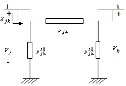 | Figure 1. Π- Equivalent circuit of line |
2. Contributions of Bus Currents
- Entire data related to the network such as bus voltages, complex line flows, slack bus power generation etc are obtained from a converged load flow solution. This section presents a direct methodology that finds the coefficients of the bus currents in the complex line flow. Once the coefficients are determined, next step is to find the allocation of transmission loss and transmission cost pertaining to individual buses.The Π equivalent circuit of a line having a line admittance
 and half line charging susceptance
  connected between the buses
 and
and  is shown in Fig. 1.
  and
and  represent the nodal voltages of buses j & k respectively.From the load flow solution we can write expression for the complex line flow Sjk in terms of the node voltage Vj and the line current Ijk through the line
  as
as | (1) |
 | (2) |
 | (3) |
 | (4) |
 from (4) in (1) and rearranging
  | (5) |
 | (6) |
 through any line j→k is represented as a function of the all bus currents; i = 1, 2, 3…..n.
  represents contribution of ith bus to j→k line power flow.
3. Transmission Loss Allocation
- Following the same procedure explained in the previous section, complex line flow from bus k to bus j i.e.
 can be expressed as
  | (7) |
 | (8) |
 represents contribution of ith bus to k→j line complex power flow i.e counter flow. It is a well established fact that, Complex line loss in any line is the algebraic sum of active and counter complex line flows. Hence, we can write
  | (9) |
 | (10) |
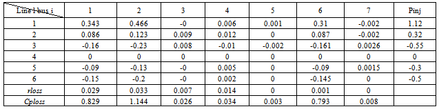
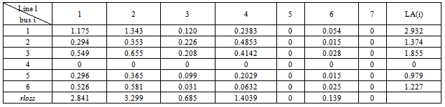
 is that it represents the contribution of ith bus to the j→k line loss and also the contribution of line j→k to the power injection at bus i. For a given power flow solution this quantity is a constant.Worked ExampleThe methodology is explained with the help of a Six bus system [10]. Two generators (located at buses 1 and 2) supply the power demand (located at buses 3, 5 and 6), while bus 4 is a zero injection (transfer) bus.The total real power loss in the system 8.37 MW is allocated among all 6 buses using the proposed method and its results are compared with those of the results obtained from existing methods in the literature.Base case bus voltages are obtained from N-R load flow solution for a six bus system whose line and bus data is shown in Tables 1 & 2At this stage, a new table is formed as shown in Table 3 and designated as [B] matrix. From close observation of the elements of Table 3, it is noticed that the algebraic sum of all elements in any row, say ith row, gives the “real power injection” at that bus i.e. ith bus power injection. Here, positive sign indicates the power generation and negative sign indicates the power demand. Further, it is to be noted that algebraic sum of all elements in any column, say lth column, gives the real power loss
  in the transmission line corresponding to that column i.e lth line. This table is useful for dual purposes i.e. transmission loss as well as cost allocations. It has been arrived at without any assumptions and the results are highly reliable.Now, using the [B] matrix, transmission line real power loss allocation among all buses can be done in the following manner.
| ||||||||||||||||||||||||||||||||||||||||||||||||||||||||||||||||||||||||
 | (11) |
 | (12) |
|
|
 | (13) |
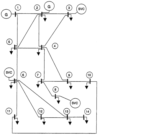 | Figure 2. IEEE 14 bus system |
| |||||||||||||||||||||||||||||||||||||||||||||||||||||||||||||||||||||||||||||||||||||||||||||||||||||||||||||||||||||||||
4. Results
- The proposed loss allocation method has been tested on IEEE 14 bus test system and the losses are allocated among the buses. Results are compared with those of the results obtained using Zbus loss allocation method, Pro-rata (PR) (considering currents and powers), Proportional sharing (PS), Incremental transmission loss (ITL) co-efficients and Loss Weight Factors (LWF) method. Line and bus data of IEEE 14 bus system given in[6] is considered. Test results of loss allocation among buses for the IEEE 14 bus system using the proposed method and the other methods are presented in Table 5. Note that all methods allot zero loss to the transfer bus which has zero injection. It is highly interesting to observe that the results obtained using the proposed method significantly differs from other methods. It is to be noted that, in the proposed method, there are no assumptions and the results are purely based on circuit laws and hence the results obtained from the proposed method may be assumed to be reliable. Further, the amount of loss allocated to any bus by the proposed method is directly reflecting the amount of real power at that bus which is a point to be considered for further research.
5. Conclusions
- In this paper, starting from a converged load flow solution, contribution factors of each complex power injection at a bus to the complex line loss in each of the transmission line are found out. At the same time, contributions of each of the transmission lines to the complex power injection at a bus are determined. These contributions allow allocation of loss among the buses based on the usage. The loss allocation factors are derived, starting from a converged load flow solution without any assumptions. In this paper a real power loss allocation methodology based on the contribution factors is established. Another significant feature of the proposed methodology is that, effect of reactive power generation and load can be easily established using the proposed methodology. Since the contribution factors derived does not involve any assumptions, there is every chance that these factors can play a vital role in the determination of Locational Marginal Prices in the present day electricity markets.
References
| [1] | “Power System Restructuring and Deregulation – Trading, Performance and Information Technology” Edited by Loi Lei Lai, John Wiley & Sons Ltd, Chichester. |
| [2] | A.J.Conejo J. M. Arroyo, and A. L. Guijarro, “Transmission Loss Allocation: A Comparison of Different Practical Algorithms”, IEEE Transactions on Power Systems, vol. 17, No. 3, pp. 571-576, August 2002 |
| [3] | J.W. Bialek, S. Ziemianek, and N. Abi-Samra, “Tracking-based loss allocation and economic dispatch,” Proceedings of 13th PowerSystems Computation Conference, Trondheim, Norway, July 1999, pp.375–381. |
| [4] | Juan Carlos Mateus, and Pablo Cuervo Franco, “Transmission Loss Allocation Through Equivalent Bilateral Exchanges and Economical Analysis,” IEEE Trans. Power Syst., vol. 20, no. 4, pp. 1799–1807, Nov. 2005. |
| [5] | F. D. Galiana, A. Conejo, and I. Kockar, “Incremental transmission loss allocation under pool dispatch,” IEEE Trans. Power Syst., vol. 17, no. 1,pp.184–188, Feb. 2002. |
| [6] | A.J. Conejo, F. D. Galiana, and I. Kockar, “Z-bus loss allocation,” IEEE Trans. Power Syst., vol. 16, no. 1, pp. 105–110, Feb. 2001. |
| [7] | A.J. Conejo, J.Contreras,D.A.Lima,A.P.Feltrin “Zbus Transmission network cost allocation,” IEEE Transactions On Power Systems, Vol. 22, No. 1, February 2007 |
| [8] | J.S. Daniel, R.S. Salgado and M.R. Irving, “Transmission loss allocation through a modified Ybus,” IEE Proc.-Gener. Transm. Distrib., Vol. 152, No. 2, pp.208-214,March 2005 |
| [9] | Qiefeng Ding, Ali Abur, “Transmission Loss Allocation Based on a New Quadratic Loss Expression” IEEE Transactions on Power Systems, vol. 21, no. 3, August 2006, pp. 1227-1233 |
| [10] | Q.Ding and A. Abur, “A Unified transmission loss allocation method”, International Journal of Electric Power & Energy Systems, Volume 29, Issue 5, June 2007, Pages 380-386 |
| [11] | J.N.Y. Cheung, T. Czaszejko, and A. B. Morton, “Transmission loss evaluation in an open electricity market using an incremental method,” IET Gener. Transm. Distrib., vol. 1, no. 1, pp. 189–196, Jan. 2007 |
| [12] | Kyung-Il Min, Sang-Hyeon Ha, Su-Won Lee and Young-Hyun Moon, “ Transmission Loss Allocation Algorithm using Path-Integral Based on Transaction Strategy”, IEEE Transactions on Power Systems, Vol. 25, No. 1, Feb. 2010, p.p. 195-205 |
| [13] | Sobhy M.Abdelkader, “Characterization of Transmission Losses,” IEEE Transactions on Power Systems., Vol. 26, No. 1, Feb. 2011, pp,392-400. |
| [14] | Keshmiri, S.N.; Ehsan, M, “Transmission loss allocation using normalized loss weight factors”, Proceedings of Third International Conference on Electric Utility Deregulation and Restructuring and Power Technologies, 2008, pp. 431-465 |
| [15] | Keshmiri, S. Nasser; Gao, Wenzhong, “Transmission Loss Allocation Using Normalized Loss Weight Factors in Bilateral Contracts Environment”, Proceedings of North American Power Symposium (NAPS), 2009 ,pp. 1 - 6 |
| [16] | Vongphan, K., Audomvongseree, K , “Transmission Loss Allocation for Mixed Pool and Bilateral Markets”, Proceedings of Sixth international Conference on Electrical Engineering/Electronics, Computer, Telecommunications and Information Technology, 2009. ECTI-CON 2009. pp.6-9. |
| [17] | Taciana V. Menezes, Luiz Carlos P. Da Silva & Marcelo S. Castro, “A Comparative Analysis of AC and DC Incremental Methods for Transmission Loss Allocation”,Electric Power Components and Systems,Volume 34, Issue 5, 2006, pp. 521-537 |
| [18] | M. De & S. K. Goswami, “A Direct and Simplified Approach to Power-flow Tracing and Loss Allocation Using Graph Theory”, Electric Power Components and Systems ,Vol. 38, Issue 3, 2010, pp. 241-259 |