Omid Zeynali 1, Daryoush Masti 2, Asghar Ebrahimi 1, Mohammad Orvatinia 3, Nezafat Maryam 1
1Islamic Azad University, Bushehr Branch, Bushehr, Iran
2Islamic Azad University, Dashtestan Branch, Borazjan, Iran
3The faculty of Information and Communication Technology (ICT)
Correspondence to: Daryoush Masti , Islamic Azad University, Dashtestan Branch, Borazjan, Iran.
| Email: |  |
Copyright © 2012 Scientific & Academic Publishing. All Rights Reserved.
Abstract
In this study, the use of shield to reduce radiation effects on electronic equipments, using software's to analyze the shield thickness and circuit radiation tolerance has been investigated. So by initial analysis of shield amount needed for radiation environment by Fluka, Geant4 software's and MCNP code, it was found out that reducing the dose on a piece of less than 10 Krad the critical value of electronic parts, only considering the effect of satellites shield (Al 1 ~ 2 gr / cm²) is sufficient to reduce the dose (self shielding effect) .Then by using Geant4 and Fluka software for space radiation environment in orbit in 1600 km, and inclination angle of 90⁰, it was found that the rate of environmental radiation in this case equal 15 Krad and protons, electrons and neutrons are the main factor in the dose mentioned in the satellite. Therefore the research was done, based on proton shield design for an electronic device in 15 Krad radiation .The shield was designed based on the use of light and heavy materials, a layer or a combination and also considering the shield geometry type by simulation.
Keywords:
Electron, Proton, Radiation Environment, Shield, Simulation
Cite this paper:
Omid Zeynali , Daryoush Masti , Asghar Ebrahimi , Mohammad Orvatinia , Nezafat Maryam , "The Design and Simulation of the Shield Reduce Ionizing Radiation Effects on Electronic Circuits in Satellites", Electrical and Electronic Engineering, Vol. 1 No. 2, 2011, pp. 112-116. doi: 10.5923/j.eee.20110102.16.
1. Introduction
Radiation environment various circuits, such as low earth orbit and the geostationary orbits and the space environment, mainly consists of solar wind (including electrons and protons), to cosmic protons and ions as primary space environment, radiation secondary space environment radiation includes electrons, neutrons and radiations from the brake on the interaction of primary radiation satellite structure materials[1] and the protons and electrons trapped in the Van Allen belts. All above radiation environments, influence spacecraft electronic devices spacecraft single event effect, displacement damage dose (DDD) and total ionization dose (TID)[2]. It is effective On the TID and DDD, will have little effect on the Single Event Effects (SEE)[3].
2. Theory and Background
Based on previous studies, a spacecraft shield design depends on several factors[4]: 1. Radiation resistance of electronic device used in spacecraft is 2-20 Krad for some parts. 2. The minimum radiation that device cannot function properly to the amount of radiation in a desired location(radiation design margin). 3. The analysis of electronic selfshield circuits. The analysis is per formed by Fluka, Geant4 and MCNP software's[5-6] and then based on three mentioned factors and the radiation effect on the target device, if necessary additional shield is designed[2,7]. In radiation shield substance of materials used in spacecraft, in addition to weakening capability, the weight and volume limitations and physical and mechanical properties should be considered.
2.1. Shield Gender and Type
Depending on the satellite and the mission, one of the spot or local shield is used. The differences between these two shied types are related to the weight, volume limitation and also the combination of those parts needed by spacecraft electronics devices[8]. For example, the local shield is preferable when a collection of adjacent devices is sensitive to radiation and should be shield. Space environment, when a few pieces on the electronic board need the shield, they are shielded by a shield layer on the entire board. But spot shield in a sensitive device is ideal in a satellite due to weight constraints, yet the most important factor to design and construct a shield is the weight and volume limitation. Required protection of sensitive components used, in space electronic board depends on environmental radiation dose in environment. Radiation dose is a function of height and fly angle of the spacecraft and also acceptable dose of sensitive parts depends on the device type. Shield thickness is usually expressed as aluminum thickness equivalent. When positive ions collide with high density materials, they split and produce many secondary particles, consequently to stop the secondary particles more thickness material is required[9]. As the light materials weaken the protons better, using these materials reduce the danger of secondary particles production. According to their low density, more volume of this material is required and against heavy materials, these materials don’t weaken the electrons and photons well. Using thick shields have some problems like, producing secondary dangerous materials as neutrons and gamma ray when radiation encounters to flake materials. Choosing useful material as a flake can reduce it too much. Less atomic constructions produce less secondary radiation (especially less neutrons)[9]. Therefore, to achieve the ideal shield, multilayered shield consist of layers with high and low density is suitable. The optimal thickness of each light and heavy layers, and the material, their arrangement can be optimized depending on the radiation environment and their arrangement also influence on dose near electronic device, sensitive to radiation. High density shield materials (such as tungsten and tantalum) and low density materials (such as polyethylene) can be considered as an ideal shield[4,10]. Also, materials such as boron 10 (B¹º), liquid hydrogen, lead enriched plastics with oxygen are named as a shield. A parameter to calculate the shield layer is stopping power and then reducing its devastating effects on semiconductors, devices and electronic equipments. The concept of stopping power is so useful, reducing the linear energy and is defined as follow[7]: | (1) |
For charged particles like protons, the S value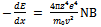 | (2) |
It is calculated in which 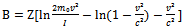 | (3) |
E and V are the velocity and a descended particle charge, Z the atomic density, N the environment atomic number and m0 the electron inertia mass. Parameter I is the ionization potential and excitation of environment atoms and generally will be measured through testing. Generally, to calculate the shield thickness, calculations are based on the total dose and the weakest segment of the satellite as a base; consider the 2 Krad radiation resistant. To simulate by MCNP[6,11] Geant4 software reliability is 3 (the radiation resistance of 6 Krad) and thus the rate of aluminum shield thickness is 4.5 mm. In Figure 1, the stopping power of protons in aluminum, than energy is shown[2]. Protons with energies of 10 Mev per mm in aluminum shield lose about 9 Mev energy. More than 85 percent of the protons in the space we consider here, are in the energy range 1 - 10 Mev are, so a little more than 1 mm thickness aluminum shield can, stop these protons within itself.
3. Shield Design
The cover design is performed based on allowed dose amount in satellite electric subsystems expressed in their catalogs. MCNP software and Geant4[6,11]simulation were used to calculate radiation shield design and all doses of ionizing, including electrons and protons trapped, solar protons and brake radiation ray were considered in this calculation. Aluminum was chosen as shielding material, because of the most usual material in satellite structure, weight properties and is shielding against radiation. Accordingly, using different transmission doses software in terms of aluminum shielding thickness was calculated and simulated. Figure 2 shows the various doses of ionizing to the different thickness of the aluminum[2].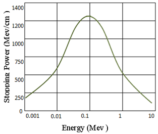 | Figure 1. Stopping power of protons in aluminum |
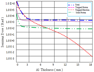 | Figure 2. Doses of ionizing depending on the radiation shield thickness |
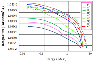
As this figure shows, electrons trapped dose is more than the other doses, but these electrons are rapidly absorbed in the shielding. The transmission dose amount through different layers of the highest dose proton particles (worst case) is simulated and presented in Figure 3.Evaluation of orbital parameters on the spectrum of space charged particles, effective on electronic equipment, altitude and orbital inclination are the most important. The effect of these two parameters using MCNP and FLUKA software was simulated. The simulation result is shown in Figures 4 to 7. As Figure 4 suggests increasing height of the orbit, extends and the range of energy protons altitudes above 400 km and entering the Van Allen radiation belts, we encounter high energy protons, and semiconductors devices are more damaged. Also at all higher altitudes, the flux of protons with lower energy is higher. This means the duration time the satellite encounter low energy protons is much more than the duration time they encounter high energy protons.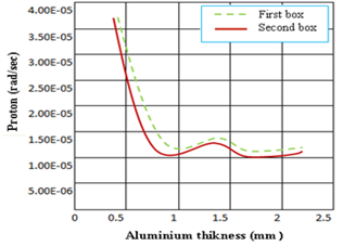 | Figure 3. Aluminum shell thickness according to dose per second |
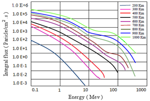 | Figure 4. The energy spectrum of protons in various LEO altitudes |
The spectrum of electron in figure 5 shows the electrons energy range (0.04 - 7 Mev) at altitudes of LEO against protons does not depend on height[1] and the rate of flux of electrons with height is much lower than the changes in protons. Also the energy spectrum of electrons shows the satellite is exposed to low energy electrons much more than exposing to energetic electrons. Figures 6 and 7 show spectra between protons and electrons with the orbital inclinations. As this figure shows, in the slope of the orbit 0 < i < 30° ,the flux of electrons and protons depends on orbital inclination too much, but in i > 30° the rate of flux changes quiet by increasing the orbital inclination. At 50° > i > 40° the particle flux behavior suddenly changes and the flux is reduce by increasing orbital inclination[7]. At i > 50° the flux of protons and electrons can be described as following, the flux of protons, is increased at low energies by increasing orbital inclination and it is decreased at high energies decrease, but the flux of electrons, is decreased by increasing orbital inclination at low energies and it is increased in high energies. 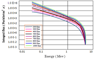 | Figure 5. The energy spectrum of electrons at altitudes of LEO |
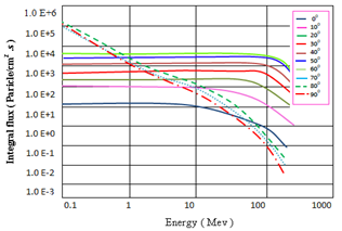 | Figure 6. The energy spectrum of protons in the slopes of different orbit |
 | Figure 7. The energy spectrum of electrons in the slopes of different orbit |
Required Shield was investigated in a height and specific declination angle to be evaluated due to its height radiation, dominant effect, substance and thickness. So using FLUKA software, diagrams of TID and DDD per 1600 Km height and declination angle 90⁰, and aluminum shield layer were obtained in two different surface densities shown in Figure 8[1]. Attending to diagram of Figure 8 shows the height of 1600 Km, needs a very stronger shield, so we will design a shield in this height.
3.1. Shield Design for the Height of 1600 Km
For designing satellite design shield, some information's such as altitude, declination angle, and the duration of the mission and objective electronic components sensitivity are required. As previously said, the flying height of 1600 Km, 90⁰ declination angle and also a 5 years mission were considered. Supposing the objective electronic device is a defected surface (RDM) is about 15 Krad[2]. Fluka and MCNP software's[5 - 6] can design the two spherical and surface geometry and the results for both the four pure materials, aluminum, polyethylene, tungsten and Tantalum and four different combinations of these materials are obtained[9]. The results of simulations and calculations in the spherical case, the initial dose regardless of the extra protection was achieved with 75 Krad tried to use a different thickness of the shield, the dose was reduced to 7.5 Krad. In the case of a flat initial dose it was 15 Krad and using a different shielding, thickness of 1.5 Krad reduced dosage level.Due to important factors of weight and volume in shield designing dose, charts depending on shield thickness, volume and mass for both spherical and flat shielding are calculated and are shown in Figures 9 and 10. As we see in Figure 9, the aluminum shielding with a thickness of about 7 cm in the spherical case, by increasing thickness, volume and mass increase move intensively, therefore light materials are used for shielding in this case[12]. This form also shows the spherical design using the Geant4 and Fluka software's, combination Ta-Poly2 of other compounds and thickness, volume and weight, pure substances has better performance, then the composition of W-Poly2,Ta-Poly,W-Poly1 then tantalum and tungsten are the aluminum and polyethylene[3]. Figure 10 shows about 6 cm thickness, aluminum shielding get for flat state thickness. Increase in flat state volume and mass increase less intensively. There is the volume restriction for light materials, and heavy materials have weight restrictions. This form is also designed for the bulk composition W-Poly2 has better performance than other compounds and pure substances and after the combination, respectively, Ta-Poly2, W, W-Poly1, Ta-Poly1 , tantalum and then have the aluminum and polyethylene. But the weight of the polyethylene in this case is better than other materials, then Al, Ta-Poly2, Ta-Poly1, W-Poly2, W-Poly1 and eventually are tantalum and tungsten[9].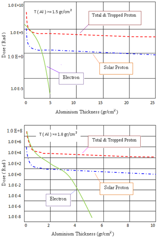 | Figure 8. DDD and TID charts for altitude, 1600Km |
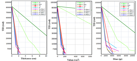 | Figure 9. TID charts in terms of thickness, volume and mass of formation material shielding break the spherical shielding |
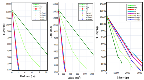 | Figure 10. TID charts in terms of thickness, volume and mass of formation material shielding break the flat shielding |
4. Conclusions
According to the simulations and calculations to reduce the effects of space radiation and the results, the flux which satellite encounters during passing through the radiation belts changes according to altitude and orbital inclination intensively. Dependence on the orbital inclination range, 0 < i < 30° is the highest. In the further slopes, i > 60°, this dependence will be too little and the most dependency of the heights occurs between 200-600 Km. Increasing altitudes, the flux increases considerably and the height increases, more when satellites will be exposed to cosmic rays and solar particles tab. But the orbital inclination is more important and by increasing it, the satellite will be exposed to these particles longer. Flat mode in Geant4 and Fluka software, not only has estimated dose less but also it estimates less thickness of the shield for electronic components. Result of the optimization process is not the same as in spherical and flat. In both spherical and flat shield, combining light and heavy materials as space radiation shielding in space is more appropriate option. According to studies done on the results of radiation test in some microelectronics devices, it has been determined that the defect of the most electronic components, is about 2-20 Krad for TID effect and the DDD effect is about 2×10¹º flux of protons 10 Mev.
References
| [1] | Bhowmik S., and Benedictus R., “Performance of Space Durable Polymeric Nano Composite under Electromagnetic Radiation at Low Earth Orbit”, the Netherlands. |
| [2] | NASA practice NO.PD-ED-1258, “Space Radiation Effects on Electronic Components in Low-Earth Orbit”, 1996. |
| [3] | Parker E.N., “Shielding Astronauts from Cosmic Rays”, Space Weather, Vol. 3, S08004, null pp., 2005. |
| [4] | Margaret R., “Effects of Material and/or Structure on Shielding for Electronic Devices”, IEEE Trans. On Nuclear Science, 1996. |
| [5] | Ferrari A., et Al., “Fluka: a multi-particle transport code,” CERN-2005-010 (2005). |
| [6] | X-5 Monte Carlo Team, “MCNP-A General Monte Carlo N-Particle Transport Code”, Los Alamos National Laboratory, April 2003. |
| [7] | ECSS-E-ST-10-12C, “Method for the Calculation of Radiation Received and its Effects, and Policy for Design Margins”, ESA’s standards, 2008. |
| [8] | Poivey C., “Radiation Hardness Assurance for Space Systems”, NASA GSFC, 2003. |
| [9] | Wilson J.W., Cucinotta F.A., Miller J., Shinn J.L., Thibeault S.A., Singleterry R.C., Simonsen L.C., and Kim M.H., “Materials for Shielding Astronauts from the Hazards of Space Radiations”, Mat. Res. Soc.Symp. Proc., 1999, pp. 551; 3-15. |
| [10] | Adams L., “A Dissymmetric Evaluation of the RadpakTM using Mono Energetic Electrons and Protons”,IEEE- trans on Nuclear Science, 1996. |
| [11] | Santinb G., Nieminen P., Evansa H., Daly E., Lei F., Truscott P.R., Dyer C.S.,Quaghebeur B. and Heynderickx D., “New Geant4 Based Simulation Tools for Space Radiation Shielding and Effects Analysis,” Nuclear Physics B., pp. 69-74, 2003. |
| [12] | Featherby M., “Advanced Conformal Coating for Radiation Shielding of Microelectronics for Space”,Maxwell Technologies Microelectronics Co., 1999. |
 Abstract
 Reference
 Full-Text PDF
 Full-Text HTML