-
Paper Information
- Next Paper
- Previous Paper
- Paper Submission
-
Journal Information
- About This Journal
- Editorial Board
- Current Issue
- Archive
- Author Guidelines
- Contact Us
Electrical and Electronic Engineering
p-ISSN: 2162-9455 e-ISSN: 2162-8459
2011; 1(1): 24-32
doi: 10.5923/j.eee.20110101.05
Optical Add Drop Multiplexer (OADM) Based on Dense Wavelength Division Multiplexing Technology in Next Generation Optical Networks
 Abstract
 Reference
 Full-Text PDF
 Full-Text HTML
A. N. Z. Rashed
Electronics and Electrical Communication Engineering Department, Menoufia University, Faculty of Electronic Engineering, Menouf, 32951, Egypt
Correspondence to: A. N. Z. Rashed , Electronics and Electrical Communication Engineering Department, Menoufia University, Faculty of Electronic Engineering, Menouf, 32951, Egypt.
| Email: |  |
Copyright © 2012 Scientific & Academic Publishing. All Rights Reserved.
The OADM based on DWDM technology is moving the telecommunications industry significantly closer to the development of optical networks. The OADM can be placed between two end terminals along any route and be substituted for an optical amplifier. Commercially available OADMs allow carriers to drop and/or add up to multi channels between DWDM terminals. By deploying an OADM instead of an optical amplifier, service providers can gain flexibility to distribute revenue–generating traffic and reduce costs associated with deploying end terminals at low traffic areas along a route. The OADM is especially well-suited for meshed or branched network configurations, as well as for ring architectures used to enhance survivability. Moreover, An optical add/drop multiplexer with tunable bandwidth offers several potential advantages, including optical performance monitoring and dynamic bandwidth allocation. This paper has proposed OADM for high transmission bit rates and products in next generation optical communication networks based on dense wavelength division multiplexing for different fiber link lengths at room temperature for best performance efficiency.
Keywords: Next Generation Network, Reconfigurable All-Optical Network, Add/drop Multiplexer, Dynamic Bandwidth Allocation
Cite this paper: A. N. Z. Rashed , "Optical Add Drop Multiplexer (OADM) Based on Dense Wavelength Division Multiplexing Technology in Next Generation Optical Networks", Electrical and Electronic Engineering, Vol. 1 No. 1, 2011, pp. 24-32. doi: 10.5923/j.eee.20110101.05.
Article Outline
1. Introduction
- Over the last decade, fiber optic cables have been Installed by carriers as the backbone of their interoffice networks, becoming the mainstay of the telecommunications infrastructure[1]. Using time division multiplexing (TDM) technology, carriers now routinely transmit information at 2.4 Gbit/s on a single fiber, with some deploying equipment that quadruples that rate to 10 Gbit/sec. The revolution in high bandwidth applications and the explosive growth of the Internet, however, have created capacity demands that exceed traditional TDM limits. As a result, the once seemingly inexhaustible bandwidth promised by the deployment of optical fiber in the 1980s is being exhausted. To meet growing demands for bandwidth, a technology called Dense Wavelength Division Multiplexing (DWDM) has been developed that multiplies the capacity of a single fiber. DWDM systems being deployed today can increase a single fiber’s capacity sixteen fold, to a throughput of 40 Gbit/s. This cutting edge technology when combined with network management systems and add-drop multiplexers enablescarriers to adopt optically-based transmission optical networks that will meet the next generation of transmitted bandwidth demand at a significantly lower cost than installing new fiber[2]. Wavelength selective optical add/drop filter is required for adding and dropping a particular Wavelength Division Multiplexing (WDM) channel at each subscriber's node in the WDM based optical access networks[2]. In these WDM based optical networks, Dense Wavelength Division Multiplexing (DWDM) technology is necessary for maximizing the limited transmission bandwidth. Add/drop filter used in DWDM based optical networks should have a good reflection characteristic, a temperature stability, a narrow spectral bandwidth, and a low implementation cost[3]. For those reasons, many researchers have been proposed various technologies for implementation of the add/drop filter. Commercialized optical add/drop filters comprise many optical passive devices such as fiber Bragg grating, thin film interference filter, circulator, and Mach-Zehnder interferometer. Although add/drop filters including those devices have good operating performances, their cost is too expensive to apply for DWDM based optical access network[4]. Future optical data transmission will change from today’s point to point connections towards transparent meshed optical networks. At the same time the increasing bandwidth demand will require much higher transfer capacities per fiber than current ones. It is still an open issue whether the increase of capacity will be accomplished by a higher number of wavelengths per fiber or by higher bit rates per wavelength or most probably a combination of both. For data rates of 80, 160 Gbit/s or more per wavelength optical time division multiplexing (OTDM) has to be applied since electronic processing is not possible yet for such high frequencies. However, the achievements of transparent networks which will be implemented for the wavelength multiplexing technology (WDM) within the next years should be conserved when introducing OTDM in addition to the WDM technology[5]. This implies the need of additional elements in the network: time domain optical add-/drop multiplexer (TD-OADM).In the present work, we have investigated OADM based on DWDM technology for high speed performance of next generation optical communication networks. We have taken in to account the bit error rate for added and dropped channels at different fiber link lengths. As well as we have developed OADM for high speed transmission bit rates and products per channel at different optical signal transmitted power. Moreover we have deeply studied the performance evolution of transmitted and received signal powers at different channels at a specific fiber link length.
2. Optical Add-Drop Multiplexing
- Time domain add drop multiplexing is schematically visualized in Figure 1. One (or more) channels can be dropped and one (or more) channels can be inserted in the empty time slot(s). A synchronized control signal simultaneously creates a drop and through function. The through operation is also called continue operation in the literature. To keep consistent with the publications the through term will be used[3,5]. The performance of various Add drop multiplexers (ADMs) are compared based on several important characteristics, namely robustness, complexity, polarization dependence, efficiency, number of tributaries and speed limitations. Several ADMs presented in literature use two control signals instead of one control signal[29,30]. The first control signal at the base rate is to provide the drop functionality and a second control signal that is a (N–1) x multiplexed clock signal to create the through function, where N is the total number of base rate channels. Although it requires a more complex clock pulse generation stage, it could relax the requirements on the functionalities of the optical switch.
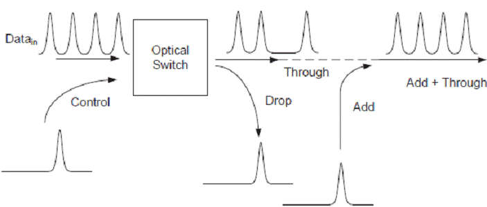 | Figure 1. Schematic function of a time domain ADM with on gate control. |
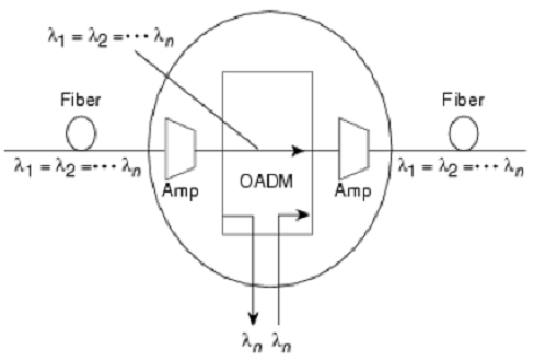 | Figure 2. Selectively removing and adding wavelengths. |
3. Modeling Analysis
- The transmitted signal power can be expressed as a function of transmitted power and fiber loss (α) in dB/km, and transmission distance in km as follows:
 | (1) |
 | (2) |
 | (3) |
 | (4) |
 | (5) |
 | (6) |
 | (7) |
 | (8) |
 | (9) |
 | (10) |
 | (11) |
 | (12) |
 | (13) |
4. Simulation Results and Discussions
- The optical add-drop multiplexer (OADM) is one of the key components for DWDM in passive optical ring networks. The OADM is used foe selectively dropping and inserting signals into a transparent DWDM. Therefore, in the present study, we have investigated and analyzed the evolution of the performance characteristics of the OADMs, moreover OADMs are taken as the major interest in optical networks to handle transmission bit rates and maximum transmission distances for the supported users at the assumed set of parameters as: polarization mode dispersion, DPMD=0.2 psec/
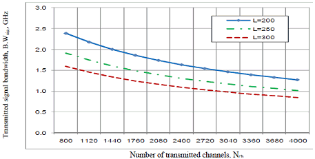
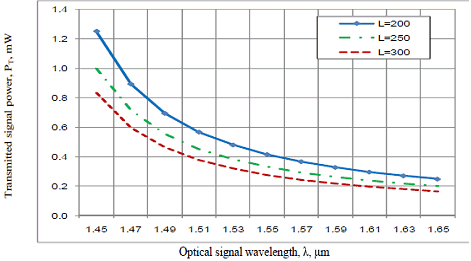
 , transmission distance, L=100-300 km, operating optical signal wavelength, λs= 1.45-1.65 μm, number of transmitted channels, Nch=800-2400 channels, ambient temperature=room temperature= 25 ºC, spectral linewidth of optical source=channel spacing, Δλs=0.1 nm, fiber loss, α at λ= 1.55 μm, and noise figure, NF=3 dB. Based on the proposed parameters above, and the results of the set of the series of the Figures (2-16), the following facts are assured as follows:i) As shown in the series of Figures (3-5) have assured that as number of transmitted channels increases, this leads to decrease in transmitted signal power, transmitted signal bandwidth, and transmission bit rate capacity at different fiber cable lengths. As well as fiber cable length increases, this results in decreasing of transmitted signal power, transmitted signal bandwidth, and transmission bit rate capacity at constant number of transmitted channels.ii) Figures (6-8) have demonstrated that as optical signal wavelength increases, this leads to decrease in transmitted signal power, transmitted signal bandwidth, and transmission bit rate capacity at different fiber cable lengths. As well as fiber cable length increases, this results in decreasing of transmitted signal power, transmitted signal bandwidth, and transmission bit rate capacity at constant operating optical signal wavelength.iii) Figures (9, 10) have indicated that as number of transmitted channels increases, this results in decreasing of received signal power at different fiber cable link lengths. As well as fiber link length increases, this results in decreasing of received signal power at constant number of transmitted channels.iv) As shown in Figures (11, 12) have proved that as number of transmitted channels increases, this results in of increasing of bit error rate at different fiber link lengths. As well as fiber link length increases, this results in increasing of bit error rate at constant number of transmitted channels.v) Figures (13, 14) have indicated that as optical signal increases, this results in decreasing of received signal power at different fiber cable link lengths. As well as fiber link length increases, this results in decreasing of received signal power at constant operating optical signal wavelength.vi) As shown in Figures (15, 16) have proved that as operating optical signal wavelength increases, this results in of increasing of bit error rate at different fiber link lengths. As well as fiber link length increases, this results in increasing of bit error rate at constant operating optical signal wavelength.
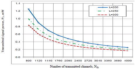 | Figure 3. Variations of transmitted signal power versus number of transmitted channels at the assumed set of operating parameters. |
 | Figure 4. Variations of transmitted signal bandwidth against number of transmitted channels at the assumed set of operating parameters. |
 | Figure 5. Variations of transmitted bit rate capacity against number of transmitted channels at the assumed set of operating parameters. |
 | Figure 6. Variations of transmitted signal power against operating signal wavelength at the assumed set of operating parameters. |
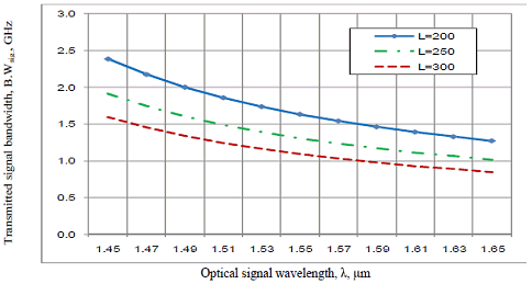 | Figure 7. Variations of transmitted signal bandwidth against operating signal wavelength at the assumed set of operating parameters. |
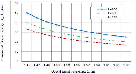 | Figure 8. Variations of transmitted bit rate capacity against operating signal wavelength at the assumed set of operating parameters. |
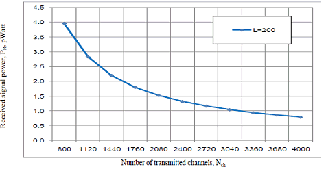 | Figure 9. Variations of optical signal received power against number of transmitted channels at the assumed set of operating parameters. |
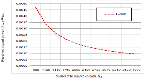 | Figure 10. Variations of optical signal received power against number of transmitted channels at the assumed set of operating parameters. |
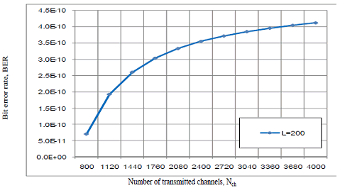 | Figure 11. Variations of bit error rate against number of transmitted channels at the assumed set of operating parameters. |
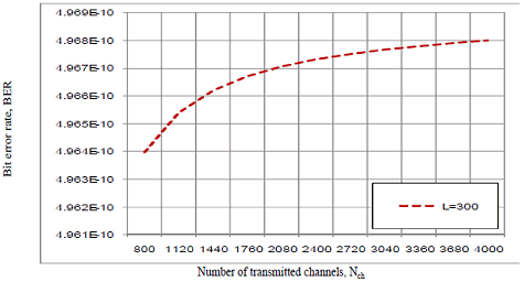 | Figure 12. Variations of bit error rate against number of transmitted channels at the assumed set of operating parameters. |
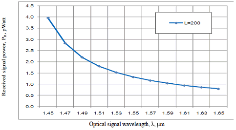 | Figure 13. Variations of optical signal received power against optical signal wavelength the assumed set of operating parameters. |
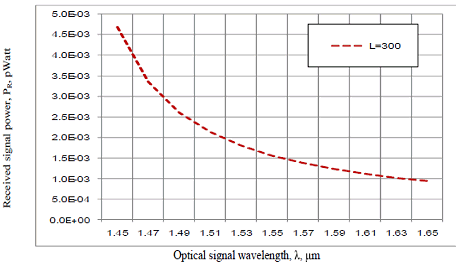 | Figure 14. Variations of optical signal received power versus optical signal wavelength at the assumed set of operating parameters. |
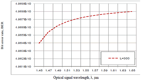 | Figure 15. Variations of bit error rate against optical signal wavelength at the assumed set of operating parameters. |
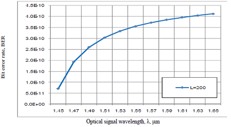 | Figure 16. Variations of bit error rate against optical signal wavelength at the assumed set of operating parameters. |
5. Conclusions
- In a summary, we have demonstrated that the OADMs are the simplest elements to introduce wavelength management capabilities by enabling the selective add and drop of optical channels based on DWDM technology in next generation optical networks. It is observed that the decreased number of transmitted channels, fiber link length, and operating optical signal wavelength, the increased optical transmitted signal power, optical signal bandwidth, and transmission bit rate capacity per all transmitted channels. As well as we have observed that the decreased of both number of transmitted channels and operating optical signal wavelength at the same fiber link length, the increased optical received power and the decreased bit error rate at the receiving side. Moreover the decreased fiber link length at constant of both number of transmitted channels and operating optical signal wavelength, the increased optical received signal power, and the decreased bit error rate at the receiving side.