H. M. Lee
Department of Electronic Engineering, Kyonggi University, Suwon, 443-760, Korea
Correspondence to: H. M. Lee , Department of Electronic Engineering, Kyonggi University, Suwon, 443-760, Korea.
| Email: |  |
Copyright © 2012 Scientific & Academic Publishing. All Rights Reserved.
Abstract
This study presents a co-planar waveguide (CPW)-fed shunt mode zeroth-order resonant (ZOR) antenna with an improved gain and radiation efficiency. The proposed antenna consisting of two symmetric unit cells has an open ended composite right/left handed (CRLH) transmission line structure. The unit cell of the proposed antenna consists of a series metal-insulator-metal (MIM) capacitor and two shorted shunt stub inductors. In order to reduce the antenna size and to improve its efficiency, a straight metal-strip line, bent by 900, was used as the shunt inductor, replacing the more traditional meander line. As a result, the total electrical size of the fabricated ZOR antenna consisting of two unit cells was 0.22 λ0  0.22 λ0. The measured gain and efficiency of the fabricated antenna have been enhanced to 3.07 dBi and 75 %, respectively, at the zeroth-order resonant frequency of 2.97 GHz, an enhancement over previously presented antennas.
Keywords:
Composite Right/Left Handed (CRLH) Transmission Line (TL), Co-Planar Waveguide (CPW), Efficiency, Gain Enhancement
Cite this paper:
H. M. Lee , "A Compact Co-Planar Waveguide-Fed Zeroth-Order Resonant Antenna with an Improved Efficiency and Gain Employing Two Symmetric Unit Cells", Electrical and Electronic Engineering, Vol. 1 No. 1, 2011, pp. 12-16. doi: 10.5923/j.eee.20110101.03.
1. Introduction
Zeroth-order resonant (ZOR) antenna manufactured on microstrip transmission lines has attracted great interest in the small antenna applications. Many techniques have been employed in order to miniaturize the composite right/left handed (CRLH) transmission line (TL) unit cell size, such as using meander line shunt stubs [1] or using the Sievenpiper’s mushroom structure[2]. In[2], a mushroom-type two unit-cells ZORA with the small size of 0.17 λ0  0.17 λ0 at 3.38 GHz was presented. The peak gain and radiation efficiency of this antenna were 0.87 dBi and 70%, respectively. In order to further reduce the antenna size, a spiral slot structure on the ground was used[3]; the measured peak gain and radiation efficiency of this antenna were – 0.28 dBi and 62%, respectively. However, small ZOR antennas employing a CRLH resonator made up of two or three cells suffer from a low radiation efficiency and poor gain in the zeroth-order resonant mode[4]. Various solutions designed to improve the ZOR an- tenna’s efficiency have been under investigation. One approach used for ZOR antenna radiation efficiency has been to increase the vertical via-hole height over the improvement ground plane using an air substrate[5]. The drawbackof this design is in the difficulties found in manufacturing the antenna. Recently, a 0.145 λ0
  0.172 λ0 at 2.03 GHz co-planar waveguide (CPW) type ZOR antenna was presented in[6]. However, its measured peak gain and radiation efficiency were only 1.35 dBi and 62%, respectively. This is thought to be due to the small radiator size, as well as from losses caused by the antenna structures, such as the shorted meander lines. In order to achieve an efficient ZOR antenna with a high gain, it is thought that the number of CRLH resonator unit cells needs to be increased[7]. Although the gain of the ZOR antenna becomes higher as the number of unit cells increases, the size of the antenna also becomes larger. In this work, a compact two unit-cell ZOR antenna with an improved gain and radiation efficiency is presented. In order to reduce the antenna size and to improve its efficiency, two symmetrical straight metal-strip lines, bent by 900, are used for the shunt inductors instead of meander lines. The proposed ZOR antenna characteristics and efficiency enhancement have been verified using CST MWS (Micro Wave Studio), a commercial 3D field simulation tool.
2. CRLH Unit Cell Design
A perspective view of the unit cell structure of the pro-posed CRLH TL and its equivalent circuit model are shown in Figure 1. The new configuration consists of two metallic layers isolated by a dielectric substrate; and each layer is made with a common ground plane, patch elements, and shunt stubs. | Figure 1. (a) The perspective view of the proposed unit cell. (b) Equivalent circuit model |
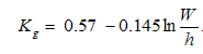
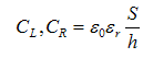
The proposed CRLH TL configuration obtains its series capacitance (CL) by using metal-insulator-metal (MIM) parallel-plate capacitors; the shunt inductances (LL) use shunt stubs shorted by via-holes to the CPW ground plane. The parasitic series inductance (LR) is provided by the MIM capacitors and the parasitic shunt capacitor (CR) is provided by the capacitance between the shunt stub line and the ground plane. The unit cells have a symmetric configuration with a CPW-fed structure. The unit cell have been designed on a FR-4 substrate (relative permittivity = 4.4, height = 0.8 mm) using microstrip technology. The values of capacitances (CL, CR) and inductances (LL, LR) can be calculated according to [8] as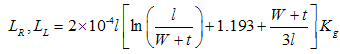 | (1) |
 | (2) |
 | (3) |
The terms  and
and  are the microstrip line width, line thickness, substrate thickness, length of the line section and area of capacitor. The determined values from the equivalent elements results in CL = 1.5 pF, LL = 4.5 nH, CR = 0.5 pF, and LR = 1.4 nH at f0 = 3.1 GHz. A ZOR antenna can be operated either in the CRLH series mode (by short-circuiting) or in the CRLH shunt mode (by open-circuiting). The antenna presented in this paper is balanced and excited open-ending, so that its energy will be confined in the shunt elements. By applying periodic boundary conditions, the CRLH TL unit cell’s dispersion relation is determined to be
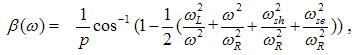 | (4) |
where p is unit cell length and 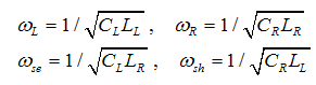 | (5) |
Under balanced resonances condition ( ), the dispersion diagram of the CRLH TL unit cell is plotted in Figure 2. As shown in Figure 2, the proposed CRLH TL exhibits balanced resonance and the transition frequency yielding f0 = 3.1 GHz. The uniform CRLH TL structure can be transformed into a resonator when it is open-ended or short-ended. A CRLH resonator with N unit cells is used, its resonance occurs when where
  is size of resonator,
  is a mode number. As a result, a CRLH resonator with
  unit cells exhibits finite
 resonance frequencies. The zeroth-order resonance mode
 corresponds to an infinite wavelength and there to a flat field distribution. This study presents a shunt mode ZOR antenna using series MIM capacitors and straight strip shunt inductors. As a result, the zeroth-order resonance mode frequency
 is determined by the shunt inductance and capacitance.
 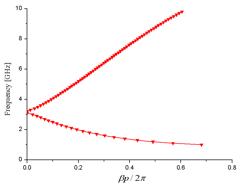 | Figure 2. Dispersion diagram of the CRLH TL used for the ZOR antenna design |
3. ZOR Antenna Design
In order to decrease this resonant frequency a meander line forming shunt inductor was used in the conventional compact ZOR antenna. In this case, the contribution from the horizontal current elements flowing in the opposed direction is eliminated at the far field. Consequently, the radiation efficiency of the ZOR antenna decreases. So the increase in the straight strip length together with bending the straight strip by 900 over the CPW ground plane should enhance the radiation efficiency. In order to further increase the shunt stub length, a via-hole was connected from the end of the shunt stub to the ground plane.  | Figure 3. Geometry of the proposed ZOR antenna: (a) Schematic view, (b) top view, (c) bottom view, and (d) equivalent circuit model |
The resultant increasing in the shunt inductance (LL) reduces the resonant frequency of the antenna. As shown in Figure 3(a)-(c), the proposed ZOR antenna consists of two element cells and a CPW feeder-line. The total electrical size of the proposed ZOR antenna is 0.22 λ0  0.22 λ0 (22 mm
  22 mm) at 3.1 GHz; the length of a unit cell is therefore p = 4.5 mm (≪ λg /4). In order to cascade two MIM capacitors in series, the lower conductor plate of the first capacitor and the upper conductor plate of the second capacitor were connected by two via-holes. The equivalent circuit model for the proposed shunt mode ZOR antenna is shown in Figure 3(d), where Cg and G are gap capacitance and shunt conductance, respectively. The extracted design parameters are as follows: CL = 1.5 pF, LL = 4.5 nH, CR = 0.5 pF, LR = 1.4 nH, and G = 0.0012 S. In addition, the gap length between the CPW feeder-line and the unit cell was adjusted in order to achieve good impedance matching for the proposed ZOR antenna to a 50 Ω coaxial probe.
  | Figure 4. Input impedance response of the proposed antenna based on the changed gap distances: (a) Input resistance and (b) input reactance. |
The dependency of the input impedance on the gap distance between the CPW feeder-line and the unit cell was investigated and the impedance responses with real and imaginary part are presented in Figure 4. As shown in Figure 4, the magnitudes of real and imaginary parts decreased as the gap distance g increases, and the resonant frequency increase markedly. When the gap distance g = 0.4 mm, the input resistance R ≈ 50 Ω, while the of the input reactance x ≈ 0 Ω at the ZOR frequency of 3.05 GHz. Therefore, the antenna was matched to a 50 Ω coaxial probe. The simulated input impedance loci of the proposed antenna are shown in Figure 5. In this case, the ZOR frequency changed from 3.1 GHz to 3.05 GHz due to the capacitance of the gap and capacitive slot. The simulated normal electric field distributions and current distributions along the metallic surfaces obtain from CST’s MWS at the simulated ZOR frequency f0 = 3.05 GHz are shown in Figure 6. It can be seen that the electric field on the MIM capacitors near uniformly distributed with equal magnitude and phase, and most of the surface current flows on the shunt strip inductor and via. The magnitude of the surface current distribution on the bottom metal plane layer of the antenna is shown in Figure 7.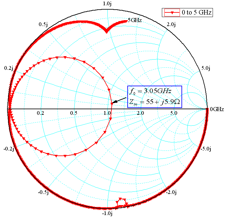 | Figure 5. Simulated input impedance loci of the proposed ZOR antenna |
 | Figure 6. (a) Normal E-field distribution and (b) surface current distribution |
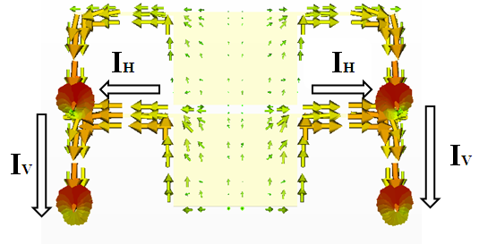 | Figure 7. Surface current distribution on the bottom metal plane layer of the antenna |
These currents on the shunt strip inductor are decomposed into two parts, named IH (horizontal component) and IV (vertical component). The horizontal component currents along the two shunt strip inductors are equal in magnitude and opposite in phase. As a result, the maximum gain radiation pattern is generated along the parallel to the shunt strip inductors (x-axis). The vertical component currents along the two shunt strip inductors are equal in magnitude and phase. As a result, the maximum gain radiation pattern is also generated along the parallel to the shunt strip inductors (x-axis). These results show that the proposed ZOR antenna with two symmetrical shunts inductors, bent by 900, exhibits an improved efficiency and gain.
4. Experimental Results
The photograph of the prototype ZOR antenna is shown in Figure 8. It was fabricated on a FR-4 substrate with the relative dielectric constant 4.4, a thickness of 0.8 mm and a loss tan δ = 0.025. The simulated and measured return loss |S11| of the fabricated ZOR antenna are shown in Figure 8. We can see that the ZOR antenna was well matched from 2.7 to 3.25 GHz, which results in a measured return loss bandwidth (-10 dB) of 55 MHz. As can be seen in Figure 9, the ZOR antenna exhibits three resonance modes (n = 0, and n = ±1) by cascading two CRLH unit cells. The measured ZOR (n = 0) frequency was observed to be f0 = 2.97 GHz. 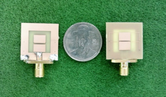 | Figure 8. Photograph of the prototype antenna |
The simulated and measured E-plane and H-plane radiation patterns at the ZOR frequency of 2.97 GHz are shown in Figure 10. The proposed ZOR antenna exhibits radiation patterns with a horizontal linear electric field polarization similar to that of a short dipole antenna along the y-axis. Since the symmetric unit cells were used, the maximum radiation direction of the antenna was along x-axis. The measured peak gain using the comparison method is 3.07 dBi, which resulted in a measured radiation efficiency of 75%. 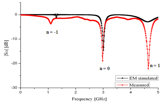 | Figure 9. Simulated and measured return loss |S11| of the ZOR antenna |
 | Figure 10. Simulated and measured radiation patterns of the proposed ZOR antenna: (a) yz-plane ( ) and (b) xz-plane ( ) and (b) xz-plane ( ), and (c) xy-plane ( ), and (c) xy-plane ( ) ) |
5. Conclusions
A compact ZOR antenna with an improved gain and radiation efficiency has been presented based on the zeroth-order resonance principle. In order to realize the compact size and enhance the radiation efficiency, two symmetrical straight metal-strip lines, bent by 90 degree, were used as a shunt inductor instead of a meander line. For the efficient operation of the proposed CPW-fed ZOR antenna a gap capacitor was used for good impedance matching to the desired ZOR frequency. As a result, the ZOR antenna was well matched from 2.7 to 3.25 GHz. The fabricated prototype ZOR antenna exhibits a horizontal linear electric field polarization with an excellent maximum gain and efficiency of 3.07 dBi and 75%, respectively, at 2.97 GHz.
ACKNOWLEDGEMENTS
This research was supported by the Basic Science Research Program through the National Research Foundation of Korea (NRF) and funded by the Ministry of Education, Science and Technology (No. 2010-0011646).
References
| [1] | A. Sanada, M. kimura, I. Awai, C. Caloz, and T. Itoh, “A planar zeroth order resonator antenna using a left-handed transmission line,” in Proc. 34th Eur. Microw. Conf., Ams-terdam, Netherlands, pp. 1341–1344, Oct. 2004. |
| [2] | A. Lai, K. M. K. H. Leong, and T. Itoh, “Infinite wavelength resonant antennas with monopolar radiation pattern based on periodic structures,” IEEE Trans. Antennas and Propag., vol. 55, pp. 868-876, Mar. 2007. |
| [3] | S. Baek, and S. Lim, “Miniaturized zeroth-order an-tenna on spiral slotted ground plane,” Electron Lett., vol. 45, pp. 1012-1024, Sept. 2009. |
| [4] | C. J. Lee, K. M. K. H. Leong, and T. Itoh, “Compact dual-band antenna using an anisotropic metamaterial,” in Proc. 36th Eur. Microw. Conf., Manchester, U. K., pp. 1044-1047, Sept. 2006. |
| [5] | D. Vrba, and M. Polivka, “Radiation efficiency improvement of the zero-order resonator antenna,” Radio engineering, vol. 18, pp. 1-8, Apr. 2009. |
| [6] | T. Jang, J. Choi, and S. Lim, “Compact coplanar waveguide (CPW)-fed zeroth-order resonant antennas with extended bandwidth and high efficiency on vialess single layer”, IEEE Trans. Antennas and Propag., vol. 59, pp. 363-372, Feb. 2011. |
| [7] | A. Rennings, T. Liebig, C. Caloz, and P. Waldow, “MIM CRLH series mode zeroth order resonant antenna (ZORA) imple-mented in LTCC technology,” in Proc. Asia-Pacific Microw. Conf., Bangkok, pp. 1-4, Dec. 2007. |
| [8] | I. Bahl, Lumped Elements for RF and Microwave Circuits: Artech House Publishers, 2003, ch. 2. |
 Abstract
 Reference
 Full-Text PDF
 Full-Text HTML