-
Paper Information
- Previous Paper
- Paper Submission
-
Journal Information
- About This Journal
- Editorial Board
- Current Issue
- Archive
- Author Guidelines
- Contact Us
Electrical and Electronic Engineering
p-ISSN: 2162-9455 e-ISSN: 2162-8459
2011; 1(1): 1-8
doi: 10.5923/j.eee.20110101.02
Power System Dynamic Stability Enhancement Using Fuzzy Controlled STATCOM
 Abstract
 Reference
 Full-Text PDF
 Full-Text HTML
D Harikrishna 1, Kamal Narayan Sahu 2, N V Srikanth
13Department of Electrical Engineering, National Institute of Technology Warangal, Warangal, 506004, India
2IBM, Bangalore, 560002, India
Correspondence to: D Harikrishna , 3Department of Electrical Engineering, National Institute of Technology Warangal, Warangal, 506004, India.
| Email: |  |
Copyright © 2012 Scientific & Academic Publishing. All Rights Reserved.
This paper aims for linearized Phillips-Heffron model of power system installed with static synchronous compensator (STATCOM) and demonstrates the application of the model in analysing the damping effect of STATCOM and designing a STATCOM stabiliser to enhance power system oscillation stability. A Single Machine Infinite Bus (SMIB) system installed with STATCOM is considered which shows the negative damping influence of STATCOM DC voltage regulator on power system oscillations and the effectiveness of AC damping stabilizer installed in the STATCOM AC voltage regulator in order to counterattack the negative damping effect is demonstrated. Fuzzy logic controller is also designed for AC damping stabilizer in order to damp out the low frequency oscillations of power system. The entire performance of SMIB system installed with STATCOM and with various damping controllers along with fuzzy AC damping controller is analysed and tested using MATLAB simulation studies.
Keywords: Dynamic stability, Damping Stabilizer, FACTS, Fuzzy logic, SMIB, Static Synchronous Compensator
Cite this paper: D Harikrishna , Kamal Narayan Sahu , N V Srikanth , "Power System Dynamic Stability Enhancement Using Fuzzy Controlled STATCOM", Electrical and Electronic Engineering, Vol. 1 No. 1, 2011, pp. 1-8. doi: 10.5923/j.eee.20110101.02.
Article Outline
1. Introduction
- An excellent power system should acquire the ability to resume to its normal operating condition after a disturbance. The quality of electric power supplied to the load is determined by its ability to supply uninterrupted power system; stability is regarded as one of the important power system research topics[1,2,3]. Power system stability can be defined as the ability of synchronous machines to remain in synchronism with each other in the event of possible disturbances such as line faults, generator and line outages and load switching etc. Depending on the order of magnitude and type of disturbances, power system stability can be classified as steady state stability, transient stability and dynamic stability[4,5].The power system may experience sustained oscillations due to small disturbances in the system. These oscillations may be local to a single generator or they may involve a number of generators widely separated geographically (inter-area oscillations). Local oscillations can occur due to a small change in the prime mover input or a small change in the terminal voltage on the generator. Inter area oscillations may appear as the system loading is increased across the weak transmission links. If not controlled, these oscillations may lead to partial or total power interruption[6]. Small-signal and transient stability studies are reported which demonstrate the effectiveness of the stabilizers in enhancing the stability of inter area as well as local plant mode of oscillations[10].Flexible AC transmission systems (FACTS) devices are power electronic based controllers that regulates the power flow and transmission voltage through rapid control action. Before the FACTS technology was introduced, power system control was focussed on the generator control, because controlling ability of transmission network was very weak. FACTS devices have the capability of controlling the transmission parameters like series impedance, shunt admittance, phase angle etc. FACTS technology is not a single high power controller but rather a collection of controllers that can be applied individually or collectively to control these parameters[7,8,9,12,13]. The functions of FACTS devices are: regulation of power flows in prescribed transmission corridors, secure loading of lines near their thermal limits, prevention of cascading outages by contributing to emergency control, damping of oscillations which can threaten security or limit the usable line capacity and improve system stability.Static synchronous compensator (STATCOM) previously known as STATCON or static condenser is converter based VAR compensator, which is an advanced static VAR compensator (SVC). STATCOM uses voltage source converters with capacitors connected on DC side. STATCOM resembles in many respects a rotating synchronous condenser used for voltage control and reactive power compensation. As compared to conventional SVC, STATCOM does not require expensive large inductors; moreover it can also operate as reactive power sink or source for wide range of operation, which makes it more attractive[24].A STATCOM plays an important role in reactive power compensation and voltage support because of its attractive steady state performance and operating characteristics. A number of studies have been performed about the dynamic behaviour of STATCOM and its applications to improve the transient performance of power systems[13,14,15,23]. However, proper control strategies are necessary in order to achieve full utilization of STATCOM. Some of the controllers designed are simple lag-lead controllers[18,22], conventional PI controllers[12,15], controllers designed by the phase compensation method[11], the linear quadratic regulators[21], pole assignment etc. Fuzzy logic controllers have also been proposed for FACTS in interconnected systems to improve the dynamic behaviour of power system[16]. The augmented fuzzy logic power system stabilizers are designed to enhance power system stability[19]. Fuzzy logic applications to SVC for dynamic stability enhancement have also been reported recently[17,25]. Selection of input signals is one of the important tasks in designing a controller for STATCOM. Some of the auxiliary input signals used for STATCOM controllers are delivered active power, the STATCOM bus voltage, computed internal voltage, synthesized remote phasor, driving point reactance seen from STATCOM location, etc [15,23]. Comparative studies of different combinations of PID controllers are presented for STATCOM[20].The majority of controllers designed for STATCOM are based on linearized model of the power system and for this reason they are suitable for a limited range of operating conditions. The load changes and unpredictable disturbances results in drastic change of operating conditions. So the linear controller designed may not perform satisfactorily. This problem of uncertainty of power system operation is handled by designing the controller to operate over a wide range of operating conditions. Such a controller is known as robust controller. Thus designing a robust controller which will operate efficiently over a wide range of operating conditions is highly desirable[14,15]. Design of non-linear controller for STATCOM based on differential algebra theory is presented[21], which allow linearizing the compensator and controlling directly the capacitor voltage output and reactive power of STATCOM.The objective of this paper is to investigate the performance of power system equipped with damping controlled STATCOM. Design of STATCOM controls have been investigated for SMIB system. Fuzzy logic controller is designed for AC damping stabilizer of STATCOM in order to damp out the low frequency oscillations of power system.
2. Power System Model with STATCOM
- The controller design for power system stability studies requires suitable mathematical representation so as to include all significant components of power system.
2.1. SMIB with STATCOM
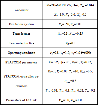
- A Single Machine Infinite Bus (SMIB) system shown in Figure 1 is considered. The STATCOM is connected at the mid-point of the transmission line.
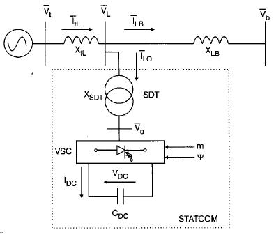 | Figure 1. STATCOM installed in a SMIB system. |
2.2. Synchronous Generator and its Excitation System
- The synchronous generator is modeled as q-axis component of voltage behind transient reactance and electromechanical swing equation representing motion of the rotor. The internal voltage equation of the generator is written as,
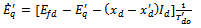 | (1) |
 is the voltage behind the transient reactance, subscripts d and q represents the direct and quadrature axis of the machine,
  is the current along the d-axis.
  and
and  are d-axis synchronous reactance, transient reactance and open circuit field time constants respectively.The electromechanical swing equation is broken into two first order differential equations and is written as,
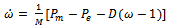 | (2) |
 | (3) |
 and
and  are the input and output powers of the generator respectively; M and D the inertia constant and damping coefficient;
  the synchronous speed; δ and ω are the rotor angle and speed;The electrical power output is,
 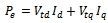 | (4) |
 and
and  are components of generator terminal voltage
  and
and  is current along the q-axis.The IEEE Type ST1 excitation system is considered in this work. The dynamic model of the excitation system is
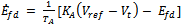 | (5) |
 represents the steady state (reference) value of terminal voltage, KA and TA are the gain constant and time constant of exciter respectively.
2.3. The STATCOM System
- The STATCOM installed in a SMIB system shown in Figure 1 consists of a step down transformer (SDT) with leakage reactance XSDT, a three phase GTO based voltage source converter (VSC) and a DC capacitor. The VSC generates a controller AC voltage behind the leakage reactance.
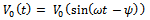 | (6) |
 produces active and reactive power exchange between STATCOM and the power system, which can be controlled by adjusting the magnitude V0 and phase
  . The voltage current relationship in the STATCOM are expressed as,
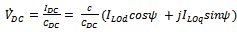 | (7) |
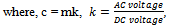 m = modulation ratio defined by PWM,
  = angle defined by PWM,
 and
and  are components of STATCOM current.The relation b/n STATCOM AC voltage
  and
and  is
is  | (8) |
 | (9) |
 | (10) |
 | (11) |
 | (12) |
 | (13) |
 and u is the vector of control variables
 .
.2.4. STATCOM Control System
- The converter and step down transformer in STATCOM can be modeled with a voltage source and a reactance for an operating point. Changing modulation ratio can change the amplitude of the output voltage of converter and so the active power absorbed by the system. By changing the converter voltage angle, reactive power exchanging with system can be controlled. In this study, the P-I controllers are used for voltage regulation.
2.4.1. Terminal voltage controller
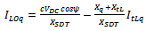
- AC voltage controller regulates the voltage of terminal according to reference which it accomplishes through changing of the converter output voltage magnitude. The terminal voltage controller is shown in Figure 2(a). The AC damping stabilizer of STATCOM is shown in Figure 2(b) is used to create an additional damping signal for STATCOM. This damping stabilizer has a structure similar to conventional PSS. In this stabilizer
 and
and  are the stabilizer input and output signals respectively.
 | Figure 2. (a) AC Voltage Controller (b) AC Damping Stabilizer. |
2.4.2. Capacitor voltage controller
- The inner DC voltage controller regulates the voltage of capacitor. The converter phase angle
 is calculated according to the reference capacitor voltage with capacitor voltage. The capacitor voltage controller is as shown in Figure 3.
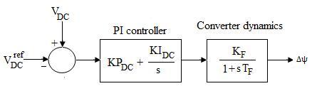 | Figure 3. Capacitor voltage controller. |
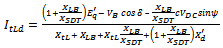
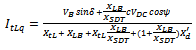
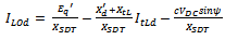
3. The Linearized Equations
- The linearized model for SMIB with STATCOM is obtained by linearizing the set of equations (13) around a nominal operating point. The linearized system equations are written as,
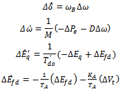 | (14) |
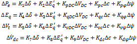 | (15) |
 | (16) |
 | (17) |
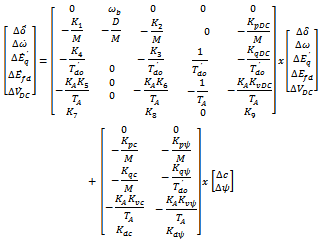
 .The block diagram of linearized Philips Heffron model of SMIB system with STATCOM is shown in Figure 4.
 | Figure 4. Block diagram of linearized Philips Heffron model of SMIB system installed with STATCOM. |
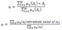
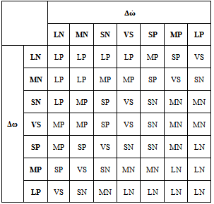
4. Fuzzy Logic Controller
- Fuzzy control systems are rule-based systems in which a set of so-called fuzzy rules represent a control decision mechanism to adjust the effects of certain system stimuli. The aim of fuzzy control systems is to replace a skilled human operator with a fuzzy rule-based system. The fuzzy logic controller provides an algorithm which can convert the linguistic control strategy based on expert knowledge into an automatic control strategy.
4.1. Fuzzy Logic Based Statcom
5. Case Studies and Results
- The effect of Voltage Regulator and Fuzzy STATCOM controller are evaluated.
5.1 Effect of Voltage Regulator
- The DC-voltage regulator controls the DC voltage across the DC capacitor of the STATCOM Figure 3 shows the dynamic model of the DC-voltage regulator, which adopts PI control. The DC-voltage regulator functions by exchanging active power between the STATCOM and the power system. Hence its influence on power system oscillation damping should be expected and can be investigated based on the Phillips-Heffron model. For example, if it is assumed that the active power input to the STATCOM installed in the SMIB power system of Figure 1 is
 .The power balance equation of the power system should be
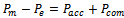 , where
  (constant) is the mechanical power input to the generator,
  is the electric power output from the generator and
  is the accelerating power to the rotor movement of the generator. In the steady-state operation mode,
  since
since  and
and . However, during the dynamic process, power balance is achieved to ensure that
 varies inversely with
  as does
  so that the active power is kept in balance. Therefore,
  is opposite to
  in phase and thus in
  of phase lead with respect to generator speed
  from eqn. 7 it can obtain
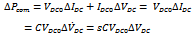 | (19) |
 lags
lags  by
by  in phase and hence is in phase with
  which can be expressed as
 Therefore, from Figure 1 and Figure 3 it can obtain the 'direct electric- torque' contribution from the DC-voltage regulator to the electromechanical oscillation loop of the generator (converter dynamics is neglected, Tc = 0)
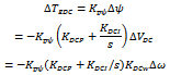 | (20) |
 , more active power is sent into the power system from the STATCOM,
  which indicates that the proportional control of the DC voltage regulator of the STATCOM provides the power system with negative damping torque, while the integral control of the DC-voltage regulator contributes no damping to system oscillations. The conclusion obtained above from the simple analysis can be confirmed by MATLAB simulation. The parameters of single-machine infinite-bus power system are given in the Appendix A1.The simulation results for the linearized model of eqn. 16, with different cases of STATCOM are shown in Figure 6.From the simulation results it can be concluded that:
5.2. Performance of Fuzzy STATCOM Controller
- The performance of the fuzzy AC damping controlled STATCOM is evaluated with Fuzzy logic controller (FLC) by MATLAB simulation studies. The SMIB system was tested with the FLC for nominal operating condition. The system data is given in the Appendix A1. The dynamic performance of the rotor angle variation (Δδ), rotor speed variation (Δω), terminal voltage variation
 and DC capacitor voltage
  variations are compared with and without fuzzy controller for the nominal operating point following 1% mechanical disturbance are shown in Figure 7. It is clearly seen that with the inclusion of FLC, electromechanical damping characteristics of the system is improved. It can be observed the fuzzy control scheme gives very good damping profile for nominal operating conditions.
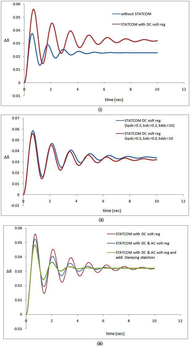 | Figure 6. Responses showing (i) Effect of DC Voltage Regulator (ii) Effect of integral control of DC Voltage Regulator (iii) Effect of STATCOM damping stabilizer. |
 | Figure 7. Comparison of responses for a 1% disturbance with and without fuzzy (i) Rotor angle variation (ii) Rotor speed variation (ii) Terminal voltage variation (iv) DC Capacitor voltage variation |
6. Conclusions
- Philips-Heffron model has been designed for Single Machine Infinite Bus system with STATCOM located at the midpoint of the transmission line. The effect of STATCOM AC and DC voltage regulator and with an additional AC-damping stabilizer were presented and discussed for power system dynamics stability studies.It is observed from the simulation results that STATCOM DC voltage regulator contributes negative damping to the power system. The STATCOM DC voltage regulator with integral control has very less effect on system damping. The STATCOM along with DC voltage regulator and AC voltage regulator without any additional control has little influence on system damping. By adding additional AC damping controller to the AC voltage regulator, the negative damping effect is further reduced.In this paper fuzzy AC damping controlled STATCOM is designed for stabilization of power system oscillations in a SMIB system where additional AC damping controller of AC voltage regulator is replaced by the proposed fuzzy logic controller. The SMIB system was tested with proposed fuzzy AC damping controlled STATCOM for nominal operating conditions. The change in rotor speed, rotor angle, terminal voltage and DC capacitor voltage fluctuations are compared with and without fuzzy logic control. It is observed that proposed fuzzy AC damping controlled STATCOM is capable of further enhancing the power system dynamic stability. It is fast and better option for damping out the electro-mechanical low frequency oscillations of power system. Hence, it can also be implemented in real-time control of power system.