Zhihang Jia, Qi Zhou, Tiger Hu Sun
Faculty of Civil Engineering and Mechanics, Jiangsu University, Zhenjiang, China
Correspondence to: Tiger Hu Sun, Faculty of Civil Engineering and Mechanics, Jiangsu University, Zhenjiang, China.
| Email: |  |
Copyright © 2022 The Author(s). Published by Scientific & Academic Publishing.
This work is licensed under the Creative Commons Attribution International License (CC BY).
http://creativecommons.org/licenses/by/4.0/

Abstract
The traditional magnetorheological damper has serious settlement in the process of use, and the amplitude modulation range of damping force and magnetic field utilization also need to be optimized. According to these characteristics, a magnetorheological grease damper with permanent magnet and excitation coil is designed in this paper. Under the action of permanent magnet, the damper ensures that the magnetorheological damper can still provide a certain damping force when there is no current supply. When there is current supply, it can increase the amplitude modulation range of damping force. Through the finite element simulation and mechanical model calculation of the magnetic field of the magnetorheological grease damper, the dynamic performance of the magnetorheological grease damper at different currents is explored.
Keywords:
Magnetorheological damper, Magnetorheological grease, Permanent magnet, Damping gap, Electromagnetic field simulation
Cite this paper: Zhihang Jia, Qi Zhou, Tiger Hu Sun, The Magnetorheological Grease Dampers with Permanent Magnets and Coils, International Journal of Control Science and Engineering, Vol. 12 No. 1, 2022, pp. 26-32. doi: 10.5923/j.control.20221201.02.
1. Introduction
Magnetorheological (MR) damper is a kind of damper that uses the rheological properties of MR materials under the action of magnetic field to provide damping force. It has the advantages of small volume, rapid response and large damping force [1]. The output damping force of MR damper is mainly affected by the effective damping gap length and coil design [2-3]. in which Yoshioka proposed a dual-coil MR damper and experimentally verified that it produced a greater damping force than that of a single-coil damper [4]. Cruze designed a multi-coil helical MR damper, which was experimentally verified for a single-layer reinforced concrete frame under seismic excitation, and effectively reduced the vibration response of the structure [5]. However, increasing the output force of the damper only by increasing the number of coils will make the structural size of the damper increase, which is not conducive to the use of MR damper in small spaces [6]. There are many similar studies, which are not listed here [7-9]. Most of the MR dampers use MR fluid to provide damping force, but the settling performance of MR fluid seriously affects the vibration damping performance of MR dampers and limits its promotion. [10]. Therefore, this paper proposes an MRG damper with the joint action of permanent magnets and coils, and finite element analysis of the magnetic field of the MRG damper is carried by ANSYS, and then the output damping force of the MRG damper in cable-damper structure is studied.
2. Structural Design
2.1. Working Principle and Structure
As shown in Figure 1, the structure of the MRG damper mainly includes parts such as piston 11, piston rod 13, left and right end caps 1, cylinder barrel 2 and excitation coil 5. The MRG damper forms a cylindrical cavity between the end caps 1 and the cylinder barrel 2, the cylindrical cavity is filled with MRG 10, and the cylinder barrel 2 and the end caps 1 are fixed by bolts 9. The piston rod 13 passes through the end caps 1 and the cylindrical cavity. A static seal design and a dynamic seal design with seal 8 and seal 14 are used at the place where the end caps 1 is connected to the cylinder barrel 2 and the piston rod 13 is connected to the end caps 1, respectively. There are two reversely wound excitation coils 5 on the piston, which are connected to the external power supply through the wire hole 7 on the piston rod 12, and there is magnetic resistance ring 4 on the outer side of the coils and an annular permanent magnet 6 on the inner side; the piston 11 is equipped with positioning tabs 3 at both ends, and the positioning tabs 3 are connected to the piston rod 13 by threads, and there are damping gaps 12 left between the upper and lower sides of the piston 11 and the inner wall of the cylinder barrel 2.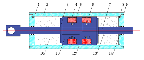 | Figure 1. MRGs damper structure |
When the piston rod 13 is reciprocating, the MRG 10 will flow to the left through the damping channel 12 to the cavity at the other end, as shown in Fig. 2. When the piston of the MR damper moves left in the cylindrical inner cavity, the MRG will move in the opposite direction through the damping channel under the compression of the piston; at the same time, when the excitation coil is energized, a magnetic field perpendicular to the direction of MRG flow will be formed at the gap of the damping channel.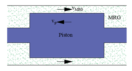 | Figure 2. Flow route of magnetorheological grease |
The magnetic circuit in a MR damper is shown in Figure 3. When the excitation coil 5 is energized, a magnetic field perpendicular to the damping gap 12 is generated. The magnetic induction lines flow out from the permanent magnet 6 and then flow through the piston 11 to the damping channel 12, which flows into the cylinder barrel 2 after passing through the damping channel 12 at the other end of the coil 5 and then into the piston 11 back to the permanent magnet 6, forming the circuit as shown in Figure 3. In this process, the length of the damping channel with magnetic induction lines passing perpendicularly is the effective working length, and the MRG flowing through this section changes from random distribution to chain structure when it is subjected to magnetic field, and the chain structure of magnetic particles seriously hinders the flow of MRG, which is the so-called magnetorheological effect.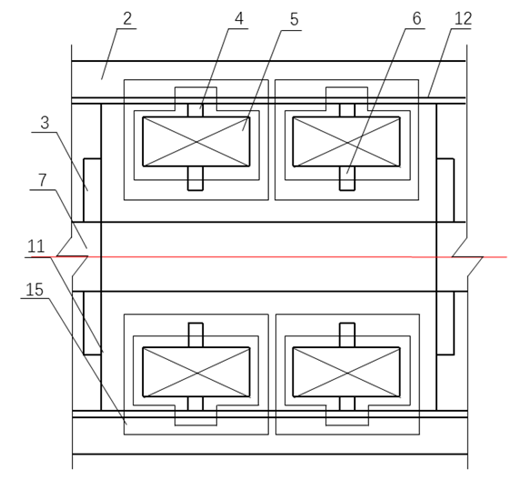 | Figure 3. Closed magnetic circuit of MR damper |
Compared with the conventional MR dampers, the MRG dampers in this paper are equipped with annular permanent magnets and magnetic resistance rings. When the excitation coil current is not zero, the excitation coil and the ring permanent magnet will generate a magnetic field in the same direction, which further enhances the magnetic field strength at the damping channel and effectively improves the damping force of the MR damper. When the current is zero, the permanent magnet provides a certain magnetic field in the event of a damper failure, and is a safety line of defense in the event of a damper failure. In addition, a damping ring is equipped on the piston between the excitation coil and the damping channel. When current is applied to the excitation coil, the magnetic induction lines generated near the damping ring are turned to pass perpendicularly through the damping channel, allowing the effective working length of the dampers to increase and improving the utilization of the magnetic field.
2.2. Mechanics Model
The dynamic characteristics of the MR damper are described using the Bingham model [11] as represented in Figure 4, which can be expressed by equation (1).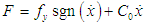 | (1) |
where F is the damping force of the MR damper; fy is the yielding force of the damper; sgn is the step function; C0 is the viscous damping coefficient of the damper after yielding, independent of the strength of the external magnetic field; and  is the velocity of the damper piston relative to the cylinder barrel.
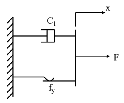 | Figure 4. Bingham model |
3. Electromagnetic Field Simulation
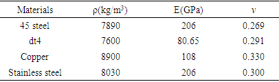
The cylinder barrel and piston rod play a supporting role in the MR damper and bear the main external pressure. therefore, the selected material should have a certain strength. The piston disc and cylinder barrel are important components of the magnetic circuit, so their materials also need to have a high relative permeability and saturation magnetic induction strength. In order to avoid magnetic leakage between the end cap and the piston rod contact place, the end cap should be made of non-conductive material. In summary, the piston rod and cylinder barrel material selection 45 steel, piston disc selection of electrical pure iron dt4, end cap selection of 316 stainless steel, specific material parameters as shown in Table 1.Table 1. Material properties of MRG damper
 |
| |
|
In Table 1, p is the density, E is the modulus of elasticity, and v is the Poisson's ratio.Since the piston part of the damper is a symmetric structure, the symmetric half of the two-dimensional model can be taken to build a two-dimensional model as shown in Figure 5 (left), in which the copper wires of the two coils of the MR damper are wound in the reverse way, which is expressed in the finite element analysis as the input current in the opposite direction in the two coils. After testing, the distribution of magnetic induction lines inside the damper is shown in Figure 5 (right).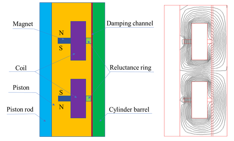 | Figure 5. Physical model of piston (left) and Magnetic induction line distribution (right) |
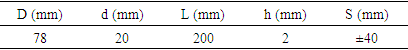
The dimensions of the preset structures of the damper model are shown in Table 2. The simulation unit is PLANE13, the relative permeability of the piston and cylinder part is set to 1000, the relative permeability of the ring permanent magnet is set to 2000, the coercivity is set to 20000A/m, the permeability of both the damping ring and the coil part is set to 1. The flux parallel boundary condition is applied, the winding direction of the wires in the two coils is opposite, the number of turns of the single coil is 500, and the applied current density can be expressed in equation (2). | (2) |
Where N is the number of turns of the coil,  is the current, and A is the cross-sectional area of the coil. Test the magnetic field distribution of MR grease damper when the current is 0, 1, 2, 3 and 4A.
Table 2. Preset structural parameters of MRG damper
 |
| |
|
In Table 2, D is the piston diameter, d is the piston rod diameter, L is the effective length of the piston, h is the damping gap height, and S is the piston stroke.In the simulation process, the MRG with mass fraction of 70% was chosen, and the relationship between its viscosity and shear yield strength and magnetic induction intensity is shown in Fig. 6. When the magnetic induction strength is less than 0.6T, the viscosity of MRG increases with the increase of magnetic induction strength, and when the magnetic induction strength is greater than 0.6T, the viscosity of MRG remains almost constant. This is because the magnetic particles in MRG are magnetized under the action of magnetic field, and the particles are attracted to each other to form a chain structure. With the increase of magnetic field strength, the number of chains keeps increasing, and the viscosity of MRG also increases, and when the magnetic induction strength reaches a certain strength, the MRG reaches the saturation state. The shear stress of MRG is similar to the variation law of viscosity. In addition, it is obvious that the shear stress of MRG is not 0 when the magnetic induction intensity is 0. The reason is that the MRG matrix has a special soap fiber structure, which has a certain binding effect on the magnetic particles when there is no applied magnetic field, and this structure is also a good solution to the settling phenomenon of MR materials.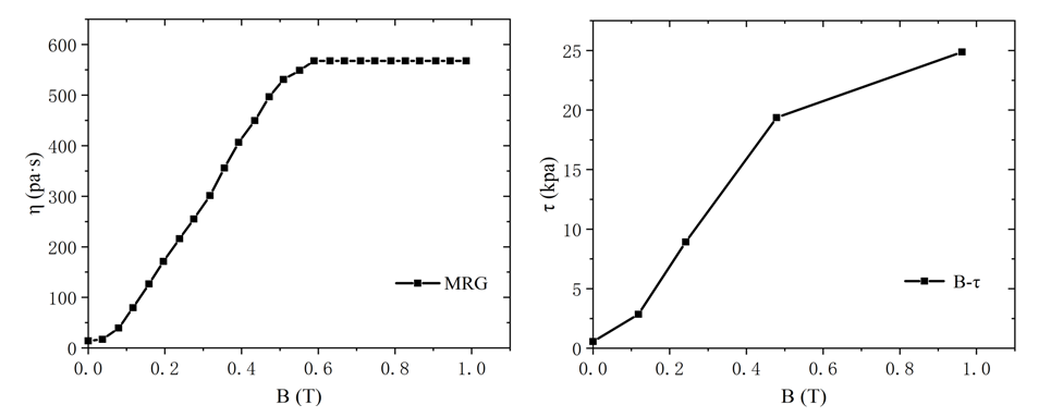 | Figure 6. Relationship between viscosity and shear yield stress of MRGs and magnetic flux intensity |
4. Results
As shown in Figure 7, the magnetic induction cloud diagram when the current is 0A and 1A. When the current is 0A, the MR damper only has the magnetic field generated by the permanent magnet part, and the magnetic induction strength is weak; while when the current is not 0A, the magnetic field inside the damper is generated by the permanent magnet and the excitation coil together, and when the two magnetic fields are in the same direction, the damping channel has a stronger magnetic induction strength, thus producing a larger damping force.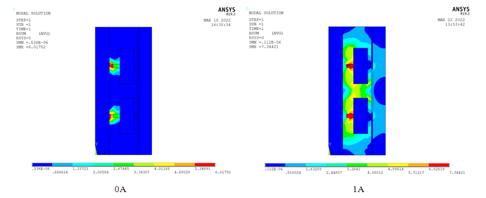 | Figure 7. Cloud diagram of magnetic induction intensity when the current is 0A and 1A |
Figure 8 shows the magnetic induction intensity distribution in the damped channel. It can be seen that the magnetic induction intensity in the damped channel can be clearly divided into three parts, in which the magnetic induction intensity in the middle part is relatively strong and that in the two ends is relatively weak.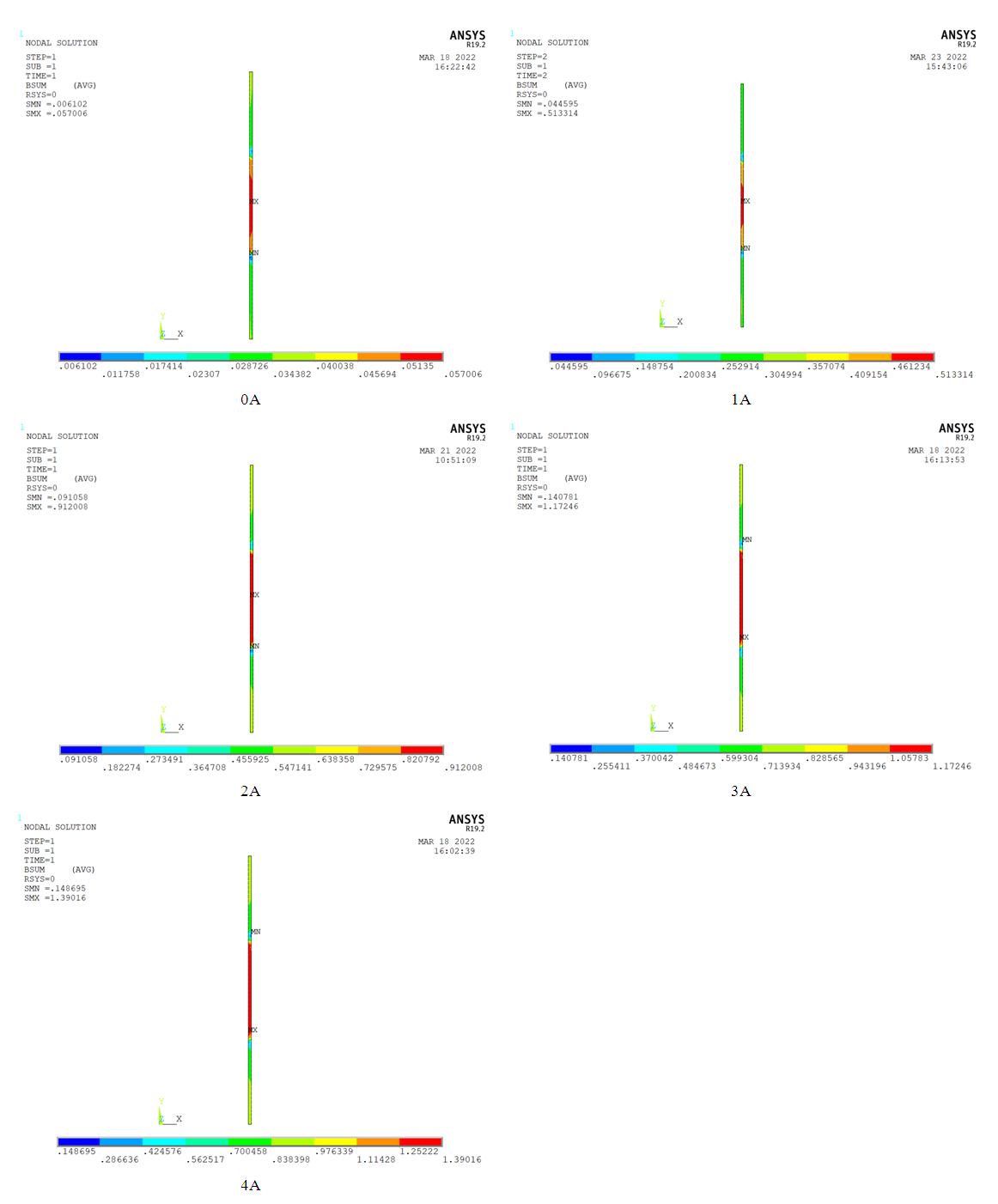 | Figure 8. Magnetic induction intensity at damping channel when current is 0, 1, 2, 3, 4A |
Therefore, the relationship between the maximum magnetic induction and the current in the damped channel can be obtained as shown in Figure 9.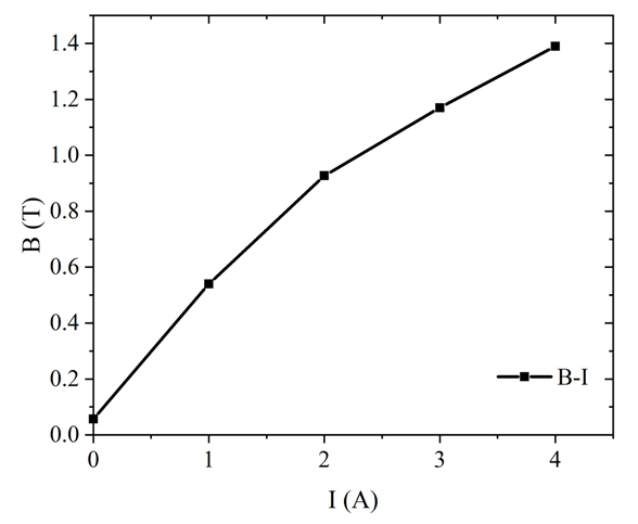 | Figure 9. Relationship between magnetic flux density and current in damping channel |
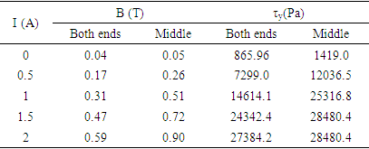
Therefore, the magnetic field and shear yield stress of MRG at different currents are shown in Table 3.Table 3. Shear stress of MRGs at both ends and middle part of damping channel
 |
| |
|
According to the simulation results, assuming that the damping channel is divided into three parts of equal length and the magnetic induction line intensity within each part is equally distributed. According to the damping force equation of the conventional shear valve type MR damper, the damping force equation of the MR damper in this paper can be expressed by equation (3).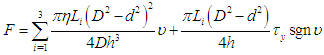 | (3) |
In equation (3),  is the zero-field viscosity of magnetorheological grease; Li is the effective length of each part of the damping channel.The above data and the preset structural parameters of the MRG damper are brought into equation (3), The damping force-displacement and damping force-velocity relationships of the MRG damper are shown in Figure 10.Figure 10 shows the variation of the damping force with displacement and velocity corresponding to different currents. From Fig. 10(a), it can be seen that when the damper piston head moves in the positive direction, its damping force value is positive, and vice versa is negative. The output damping force for the same displacement is symmetric about F=0 at the same current. At the same current, the output damping force is maximum when the displacement is 0, and the output damping force decreases gradually with the increase of the absolute value of displacement. As can be seen from Fig. 10(b), when the piston head velocity is 0, the output damping force value is 0. During the velocity loading process, the magnitude of the output damping force presents central symmetry about the velocity zero point, and the damping force values in the positive and negative directions are equal in magnitude and opposite in sign. The damping force increases with the increase of motion speed and in the same direction.
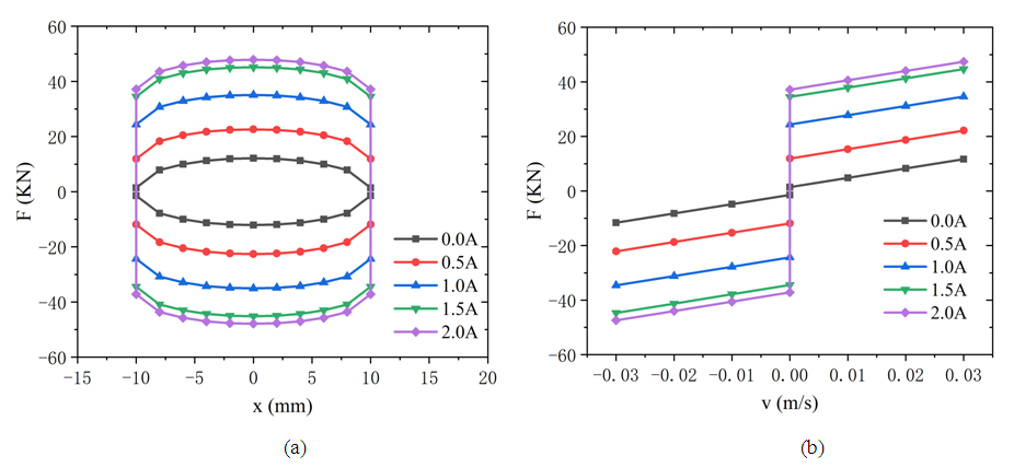 | Figure 10. Relationship between output damping force and (a) displacement and (b) velocity under different currents |
5. Conclusions
1. An MRG damper with the joint action of permanent magnet and excitation coil is designed, which can change the output damping force of the magneto-rheological grease damper by adjusting the direction of the input current, making the damper have a wider adjustment range.2. According to the finite element simulation results of magnetic field, it can be seen that the magnetic force line passes through the damping channel vertically, and the magnetic field provided by the permanent magnet still exists at the damping channel when the external input current is 0A, which ensures that the MRG damper can still provide certain damping force when there is no current input; the existence of the damping ring almost makes the full channel of the damping gap effective, which improves the utilization of the magnetic field and the output force of the damper; the existence of permanent magnet can reduce the heat production of the coil to a certain extent, which reduces the influence of temperature change on the MRG.3. According to the relationship curves of the damping force of the damper with displacement and velocity under no current, it can be obtained that the displacement and velocity have less influence on the output damping force, and the current size is the main factor affecting the output damping force. Therefore, when using MR dampers for damping control, the input current can be set according to the actual working condition.
ACKNOWLEDGEMENTS
This work was financially supported by The National Natural Science Foundation of China (Grant No. 11702116), The National Natural Science Foundation of Jiangsu in China (Grant No. BK20160484), and the Foundation of Jiangsu University (14JDG162).
References
| [1] | Liu G, Gao F, Liao W H. Magnetorheological damper with multi-grooves on piston for damping force enhancement[J]. Smart Materials and Structures, 2020, 30(2): 025007. |
| [2] | Saini R S T, Chandramohan S, Sujatha S, et al. Design of bypass rotary vane magnetorheological damper for prosthetic knee application[J]. Journal of Intelligent Material Systems and Structures, 2021, 32(9): 931-942. |
| [3] | Yang Y, Xu Z D, Guo Y Q, et al. Internal magnetic field tests and magnetic field coupling model of a three-coil magnetorheological damper[J]. Journal of Intelligent Material Systems and Structures, 2020, 31(19): 2179-2195. |
| [4] | Yoshioka H, Ramallo J, Spencer Jr B. “Smart” base isolation strategies employing magnetorheological dampers[J]. Journal of engineering mechanics, 2002, 128(5): 540-551. |
| [5] | Cruze D, Gladston H, Farsangi EN, et al. Seismic performance evaluation of a recently developed magnetorheological damper: experimental investigation[J]. Practice Periodical on Structural Design Construction, 2021, 26(1): 1-14. |
| [6] | Hu G, Liu H, Duan J, et al. Damping performance analysis of magnetorheological damper with serial-type flow channels[J]. Advances in Mechanical Engineering, 2019, 11(1): 1-12. |
| [7] | Jiang M, Rui X, Yang F, et al. Multi-objective optimization design for a magnetorheological damper[J]. Journal of Intelligent Material Systems Structures, 2022, 33(1): 33-45. |
| [8] | Jae-Hoon L, Changwan H, Dongsu A, et al. Design and performance evaluation of a rotary magnetorheological damper for unmanned vehicle suspension systems[J]. Scientificworldjournal, 2013, 2013: 1-10. |
| [9] | Jamadar M-e-H, Desai RM, Saini RST, et al. Dynamic analysis of a quarter car model with semi-active seat suspension using a novel model for magneto-rheological (MR) damper[J]. Journal of Vibration Engineering Technologies, 2021, 9(1): 161-176. |
| [10] | Zhao P, Li X, Tong Y, et al. Effect of the interface between magnetic particles and carrier liquids on magnetorheological properties and sedimentation of magnetorheological fluids: A molecular dynamics simulation and experimental insights[J]. Journal of Molecular Liquids, 2021, 342: 1-9. |
| [11] | Shames IH. Elastic and inelastic stress analysis[M]: CRC Press; 1997. |

 Abstract
 Reference
 Full-Text PDF
 Full-text HTML