-
Paper Information
- Paper Submission
-
Journal Information
- About This Journal
- Editorial Board
- Current Issue
- Archive
- Author Guidelines
- Contact Us
International Journal of Control Science and Engineering
p-ISSN: 2168-4952 e-ISSN: 2168-4960
2019; 9(1): 9-14
doi:10.5923/j.control.20190901.02

Improving the Regulatory Response of PID Controller Using Internal Model Control Principles
 Abstract
 Reference
 Full-Text PDF
 Full-text HTML
Arun R. Pathiran
Dept. of Electrical and Electronics Technology, Federal TVET Institute, Addis Ababa, Ethiopia
Correspondence to: Arun R. Pathiran, Dept. of Electrical and Electronics Technology, Federal TVET Institute, Addis Ababa, Ethiopia.
| Email: |  |
Copyright © 2019 The Author(s). Published by Scientific & Academic Publishing.
This work is licensed under the Creative Commons Attribution International License (CC BY).
http://creativecommons.org/licenses/by/4.0/

The Internal Model Control (IMC) Scheme is the model based control structure, while the conventional feedback scheme with Proportional plus Integral (PI) and Proportional plus Integral plus Derivative (PID) controller is the most widely used control structure in industry. The proposed scheme combines these two schemes to attain an improved input disturbance rejection response. The regulatory response to the changes in the input disturbance can be improved via tuning the IMC controller where the response to the setpoint changes is undisturbed. Comparisons and simulation results are presented to illustrate the effectiveness of the proposed two degrees of the freedom control scheme.
Keywords: IMC, PID, Regulatory response
Cite this paper: Arun R. Pathiran, Improving the Regulatory Response of PID Controller Using Internal Model Control Principles, International Journal of Control Science and Engineering, Vol. 9 No. 1, 2019, pp. 9-14. doi: 10.5923/j.control.20190901.02.
Article Outline
1. Introduction
- The proportional integral (PI) and proportional integral derivative (PID) controllers are the widely used controllers in the process industries due to their simplicity, robustness and wide ranges of applicability in the regulatory control layer [1]. A survey of more than 11,000 controllers in the process industries reports that more than 97% of the regulatory controllers utilize the PID algorithm [2]. The PID tuning rules proposed by various authors have been compiled and reported in [3, 5]. Large numbers of tuning procedures have been proposed in the literature to tune PID controllers for different objectives and specifications. These tuning procedures can be classified as model based approaches and non-model based approaches whereas, in the former process models are used to tune PID controllers and in the later process information is used to tune PID controllers [4, 5].The direct synthesis method [6] and IMC-PID tuning method [7, 8] are the popular model based PID tuning methods for achieving desired setpoint tacking responses. These methods do not necessarily result in PI/PID controllers; however, by approximating the process models into First Order Plus Dead Time (FOPDT) or Second Order Plus Dead Time (SOPDT) models, the controller form can be reduced to that of PI/PID controller. In these methods, closed loop time constant, i.e. the IMC filter time constant is a single convenient tuning parameter to adjust the closed loop response and robustness [9]. The direct synthesis approaches and IMC-PID approaches yield very good performance for setpoint changes, but the load disturbance responses for lag-dominant (including integrating) processes with a small time-delay/ time-constant ratio is found to be unsatisfactory [10, 11].The well-known PID controller tuning rule proposed by ZN shows better disturbance rejection performance than IMC-PID design methods for lag dominant processes [12]. In order to improve the regulatory response, a new type of IMC filter was chosen and IMC-PID tuning rule was derived [13]. A direct synthesis design based PID controller tuning relations were derived for closed loop disturbance model [10]. To avoid excessive overshoot in the set-point response, a set-point weighting factor is utilized. Considering the filter structure of [13] IMC-PID, tuning relations are derived by approximating the IMC controller using Maclaurin series [9]. A model reduction technique to reduce the high-order process model into a low-order model was proposed and also the simplified IMC-PID tuning rules were proposed by considering the lag-time dominant processes [14]. A new IMC filter for disturbance rejection is taken in [15] and the corresponding analytical IMC-PID tuning relations were derived. The modified integral time constant of PID controller offers improved regulatory response. On the other hand, it also gives undesired overshoot in the servo response. This overshoot can be minimized by means of a setpoint filter.Feedforward compensation plus feedback controller scheme provides two degrees of freedom control and it allows two different design objectives to be satisfied the feed forward compensation is mainly used for dominant disturbance rejection and it needs transfer function model of the process [16]. It may be noted that the feedback controller will provide compensation for the possible model inaccuracies. The disturbance observer (DOB) can be used to estimate the disturbances, and then the estimated value can be used in the feed forward compensation scheme [17]. In this work, the feedback PID controller and IMC scheme are combined to achieve satisfactory servo as well as regulatory performances. The IMC controller is designed to achieve improved disturbance rejection performance, without sacrificing the servo performance and also it provides compensation for the external disturbances and process parameter variations. The feedback controller will provide compensation for the external disturbances and process parameter variations. The detailed design procedure of the proposed scheme is presented in section 2 and the simulation examples are reported in section 3 followed by concluding remarks in section 4.
2. Combined Feedback plus IMC Control Scheme
- A. Feedback plus IMC control schemeThe combined feedback plus IMC control scheme is shown in Figure 1. The signals
 and
and  are reference, disturbance and process output respectively.
  and
and  are the process and its model respectively.
  and
and  are the PI/PID and IMC controller respectively. The process and model response is compared to separate the disturbance response. From the response the disturbance is estimated using the IMC controller which contains an inverse of the process model. The estimated value is being used to compensate for the unmeasured disturbance. It should be noted that the IMC enables the designer to improve the disturbance response without altering the servo response.
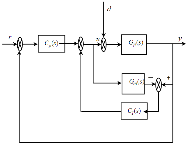 | Figure 1. Feedback plus IMC Control Scheme Scheme |
 | (1) |
 | (2) |
 is the model error i.e.
 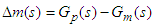 . Assume that the process model
  is perfect and exactly matches with the process behavior i.e.
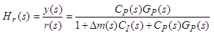
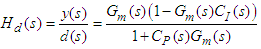
  then the closed loop transfer functions are as follows:
 | (3) |
 | (4) |
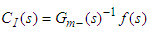 | (5) |
 is the invertible portion of the process model and
  is the IMC filter. Usually the filter has the following form:
 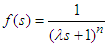 | (6) |
 is the order of the filter and it is selected based on the process model and
  is the only tuning parameter. It could be noted that the lower values of
  improves the disturbance prediction capabilities [10].B. Tuning of the proposed control schemeAs shown in equations 3 and 4 the stability of the proposed control system is function of only PID controller. The regulatory response can be modified independently by tuning the IMC controller. In this work, the Simplified IMC tuning rules proposed by Skogestad is considered to tune the primary PI/PID controller. Then, the IMC controller is tuned to improve the regulatory performance.Steps involved in the design of the proposed control schemeŸ Tune the PID controller using Simplified IMC PI/PID tuning rules and thenŸ Tune the IMC filter parameter
  to achieve the desired regulatory performance.From equations 1 and 2 it can be inferred that the process characteristic equation is function of Model Plant Mismatch (MPM) (
 ). The model inaccuracy affects the closed loop performance and robustness. Lower values of
  improve the disturbance response. On the other hand, it affects the robustness of the closed loop system in case of MPM. While designing the IMC controller, the process uncertainties has to be considered to yield a stable closed loop performance. In the proposed scheme, the number of tuning parameters has increased by one compared to the conventional PI/PID controller.
3. Simulation Examples
- The following series form of PID controller is used in the combined and SIMC-PID control schemes in the all simulation examples:
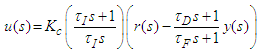 | (7) |
 .where
  is the controller gain,
  the integral time,
  the derivative time,
  filter time constant and
  the filter time constant factor. In order to avoid derivative kick, derivative on measurement is implemented. The value of
  has been chosen in the simulation study. This value was chosen in order to not bias the results, but in practice (and especially for noisy processes) a larger value of
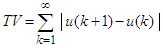
  in the range 0.1–0.2 is normally used [14].The performance of the proposed control scheme is validated through the simulation examples. To evaluate the controlled systems performance, a unit step setpoint change (r=1) and a unit step input (load) disturbance (Gd=GP and d=1) has been considered. The output performance metrics namely Integral absolute error (IAE) and the input performance metrics namely total variation (TV) of the manipulated input
  are used as the evaluation criteria for the comparison. The IAE and TV values are defined as follows:
 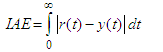 | (8) |
 | (9) |
 is a classical measure of closed-loop system robustness. The reciprocal of
  is the shortest distance between the Nyquist curve of the loop transfer function and the critical point. The typical values of
  should be in range 1.2-2.0. The maximum sensitivity is then given by,
 | (10) |
 over 1.2-2.0 corresponds to a gain margin of 6.0-2.0 and a phase margin of 49.2-29.0 [10]. Moreover, the performance is compared with the Simplified IMC and ZN PI/PID control schemes.B. Comparison with other tuning methodsSimplified IMC-PID settingThe process models are usually represented in the following form
 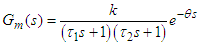 | (11) |
 is the process gain,
  are the process time constants, and
  the dead time. In [14] PI and PID settings are derived for FOPDT and SOPDT process models. The SIMC-PID setting for series form of PID controller is as follows:
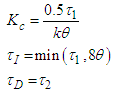 | (12) |
 | (13) |
 and
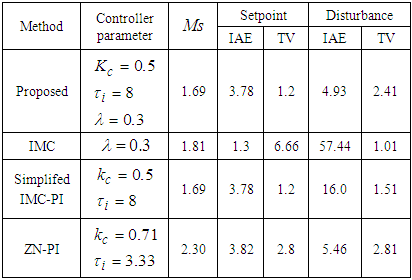
and  are the process ultimate gain and ultimate period. Example 1Consider a lag dominated FOPDT process model
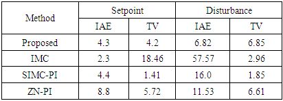
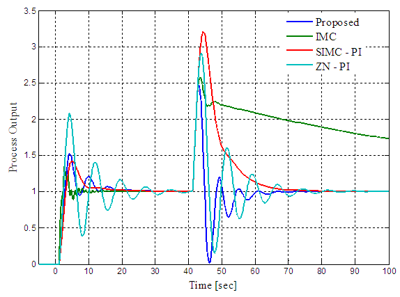
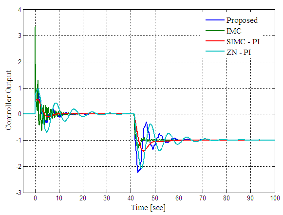
 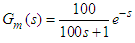 , the proposed combined control scheme PI controller is designed using SIMC tuning relation. To improve the regulatory response the IMC controller filter constant is chosen as 0.3. The IMC, SIMC-PI and ZN-PI control schemes are also tuned and the controller parameters are reported in Table 1. The setpoint-disturbance responses of the control schemes are simulated and shown in Figure 2. The controller responses are also shown in Figure 3. The performance measures are computed for the designed control schemes and reported in Table 1. The roboustness measure
  is computed and also reported in Table 1.
|
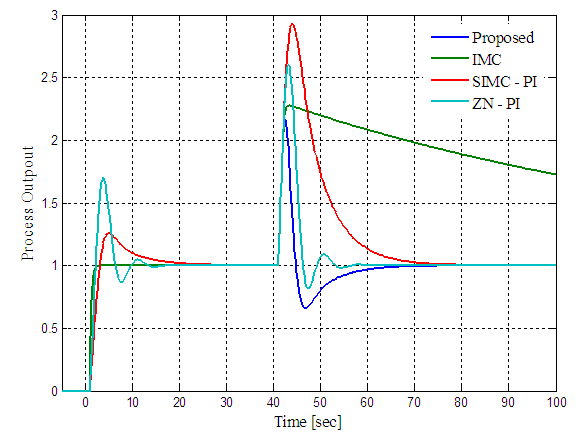 | Figure 2. Servo-regulatory response of the proposed control scheme, IMC, Simplified IMC-PI and ZN-PI control schemes for FOPDT process |
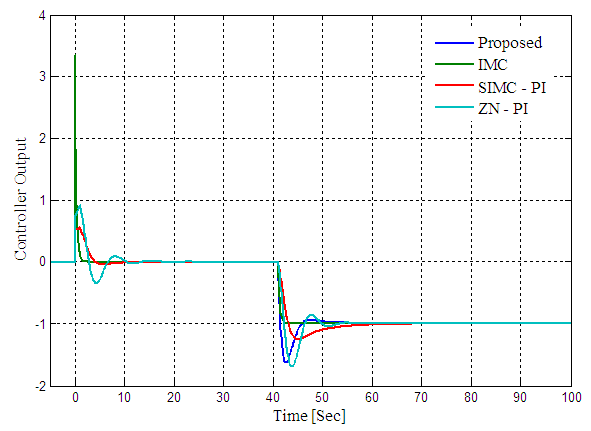 | Figure 3. Controller response of the proposed control scheme, IMC, SIMC-PI and ZN-PI control schemes for FOPDT process |
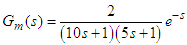 , the combined control scheme PID controller is designed using SIMC PID tuning relations and the IMC controller filter constant is chosen as 1. The IMC, SIMC-PID and ZN-PID control schemes are also tuned and the controller parameters are reported in Table 2. The setpoint-disturbance responses of the control schemes are shown in Figure 4. The controller responses are shown in Figure 5. The performance and robustness measures are computed for the designed control schemes and reported in Table 2. From the performance measures and responses it can be inferred that the IMC scheme gives very good servo response with very high controller output variations. Also, its regulatory response is not satisfactory as compared with other schemes. When the IMC scheme is combined with the feedback control scheme the regulatory performance has remarkably improved without altering the servo response of feedback controller.
|

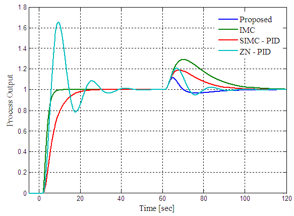 | Figure 4. Servo-regulatory response of the proposed control scheme, IMC, SIMC-PID and ZN-PID control schemes for SOPDT process |
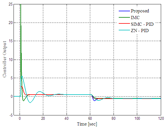 | Figure 5. Controller response of the proposed control scheme, IMC, SIMC-PID and ZN-PID control schemes for SOPDT process |
|
 | Figure 6. Servo-regulatory response of proposed scheme, IMC, SIMC-PI and ZN-PI control schemes for FOPDT process with +30% uncertainty |
 | Figure 7. Controller response of proposed scheme, IMC, SIMC-PI and ZN-PI control schemes for FOPDT process with +30% uncertainty |
4. Conclusions
- Two degrees of freedom control scheme has been proposed by combining the feedback and IMC controller. The servo response depends upon the primary feedback controller and the regulatory response can be tuned independently via IMC controller. The proposed scheme uses the IMC principles to achieve an improved performance for the input disturbances. IMC controller filter parameter
 is the only additional tuning parameter and by tuning this parameter, regulatory performance can be improved without sacrificing the servo performance. The simulation results show that the proposed scheme gives improved regulatory response than the SIMC-PI/PID controller and gives improved servo-regulatory performance than the ZN-PI/PID controller.