Alexandre Boum, Nyobe Yome Jean Maurice, Leandre Nneme Nneme, Laure Mafonang Mbumda
University of Buea, Cameroon / HTTTC Kumba
Correspondence to: Alexandre Boum, University of Buea, Cameroon / HTTTC Kumba.
| Email: |  |
Copyright © 2018 The Author(s). Published by Scientific & Academic Publishing.
This work is licensed under the Creative Commons Attribution International License (CC BY).
http://creativecommons.org/licenses/by/4.0/

Abstract
This paper presents the fault diagnosis of a three-phase induction motor using fuzzy logic, neural network and hybrid system. Detailed analysis during voltage unbalance, open phase, low voltage and overload motor fault using these strategies are presented. Stator currents were measured and their root mean square were derived. These values were used to train data. Each output of these diagnosis tools is used to determine the motor conditions whether it is in a healthy state or in a faulty one. A novel hybrid system is design and used in fault diagnosis. Simulation results show that hybrid systems give the best estimation of faults and can be therefore used in monitoring of induction motors with greater efficiency.
Keywords:
Fuzzy logic, Neural network, Hybrid system, Induction motor
Cite this paper: Alexandre Boum, Nyobe Yome Jean Maurice, Leandre Nneme Nneme, Laure Mafonang Mbumda, Fault Diagnosis of an Induction Motor based on Fuzzy Logic, Artificial Neural Network and Hybrid System, International Journal of Control Science and Engineering, Vol. 8 No. 2, 2018, pp. 42-51. doi: 10.5923/j.control.20180802.03.
1. Introduction
Diagnostic of industrial processes is a scientific discipline aimed at the detection of faults in industrial plants, their isolation, and their identification [9, 16]. Many scientific researches deal with the problem of induction motors faults detection and diagnosis and the major difficulty is the lack of accurate model that describes a fault motor [7, 9]. In fact, a fuzzy logic approach, neural networks and hybrid system may help to diagnose an induction motor faults. It is very important in this project to do analysis, comparison and data collection to acknowledge the behavior of the induction motor conditions and determine the causes of the faults occurrence using fuzzy logic, neural network and hybrid system. Moreover, this will be done throughout modeling of induction motor, estimation of the state of the faults that can occur on a such a motor, the use of fault diagnosis method by fuzzy logic, neural and the combination of both paradigm (hybrid system). This paper is organized as follow: in section 1, introduction is presented. Section 2 presents the modeling of an induction motor. In section 3, 4 and 5, fault detection of this machine is studied using the stated methods. And finally, results, discussions and conclusion are presented in section 6 and 7.
2. Modeling of Induction Motor
The model use is derived from [3, 8], and [6]. Modeling of asynchronous motor is based on many assumptions among which we have:• Gap perfectly smooth;• Negligible iron losses;• Saturation is negligible in the magnetic circuit• Negligible space harmonics; The winding of the stator and the rotor are sine distributed in such a way that mutual inductances between the stator and the rotor are sine functions of the mechanical position of the rotor with respect to the stator.
2.1. Electrical and Mechanical Equations in Three-phase System
Electrical diagram of an asynchronous motor is shown in Figure 1. Were U s(abc), U r(abc) are respectively voltages apply to the stator and the rotor.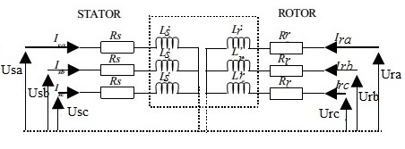 | Figure 1. Electrical diagram of an asynchronous motor [3, 8] |
From Figure 1, the following equations are derived:• For the stator side 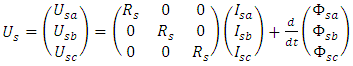 | (1) |
• For the Rotor side 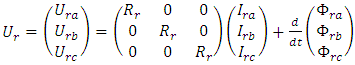 | (2) |
Where 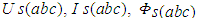 represent respectively voltages, currents and fluxes for the stator side.Similarly,
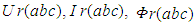 are respectively voltages, currents and fluxes for the rotor side.For squirrel cage induction motor,
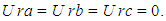 Electromagnetic torque is
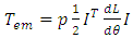 | (3) |
Where θ denotes the electrical angle between a phase of the rotor and the corresponding phase of the stator [3, 8].The mechanical equation is: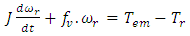 | (4) |
2.2. Electrical and Mechanical Equations in dq Reference Frame
After making Park transformation, equations below in dq reference frame are as follow:Stator side: Ø Voltages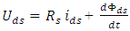 | (5) |
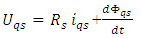 | (6) |
Ø Fluxes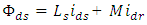 | (7) |
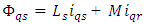 | (8) |
Rotor side:Ø Voltages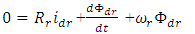 | (9) |
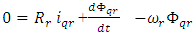 | (10) |
Ø Fluxes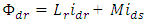 | (11) |
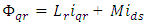 | (12) |
Electromagnetic torque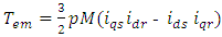 | (13) |
Angular velocity 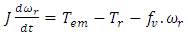 | (14) |
Voltage apply to the statorUa, Ub and Uc are three phase balanced source. This system (abc) to dq transformation is given by: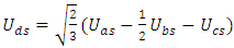 | (15) |
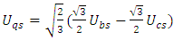 | (16) |
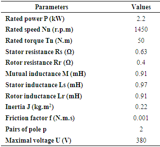
All these set of equations were used for modeling of three phase squirrel cage motor with Matlab/Simulink software.The parameters of this induction motor are shown on Table 1.Table 1. Parameters of motor
 |
| |
|
3. Fuzzy Logic in Fault Diagnosis of Induction Motor
3.1. Stator Current Monitoring System
Figure 2 shows how stator currents were used for diagnosis.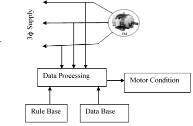 | Figure 2. Block diagram of induction motor condition monitoring system [7] |
After measuring these currents, their Root Mean Square were transferred into the corresponding discourse universe as inputs [7]. The fuzzy logic inference engine evaluates the inputs using the knowledge base [15, 17, 5, 7] and then diagnoses the motor conditions. In this final step, where fuzzy actions are reconverted to crisp ones, the “center of area” method has been adopted. According to this method, first each affected output membership function is cut at the strength indicated by the previous max-rule, next the gravity center of the possible distribution is computed and it becomes the crisp output value [7, 17, 5].
3.2. Creating If-Then Rule
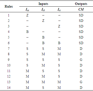
Fourteen (14) rules have been created as shown on Table 2. These rules are optimized in such a way that the healthy and the faulty cases are covered.Table 2. If-then rule of stator monitoring [7]
 |
| |
|
For inputs membership functions, Z, S, M, and B, represent respectively the linguistics variables Zero, Small, Medium and Big.For output membership functions G, D, and SD, represent respectively the linguistics variables Good, Damage and Seriously Damage.Figure 3 represents the membership functions of the inputs (Isa, Isb and Isc) and the output (CM: Condition Monitoring) of the system.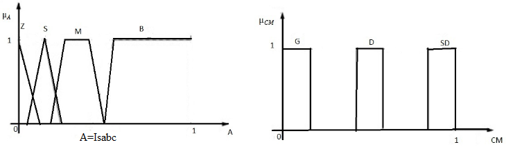 | Figure 3. Input-Output membership function: input (left), output (right) [7] |
4. Neural Network for Induction Motor Fault Identification
Data used here are generated from Root Mean Square values of three phase currents of asynchronous motor as shown on Figure 2. The entire neural network has the following parameters:* Type of the network: Radial Basis Function neural network (RBF),* supervised learning as shown on Figure 4* Three inputs (Isa, Isb, and Isc)* One output (Condition monitoring)* Two (02) layers: one input layer and one output layer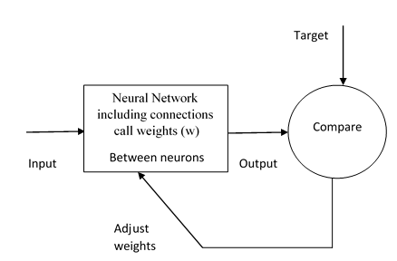 | Figure 4. Functional block diagram of ANN, [18] |
The network was trained in such a way that healthy and faulty conditions are covered. It output varies between zero (0) and one (1). When this output approaches zero (0) this means that the motor is healthy, and when it approaches one (1), this means that the motor is faulty. Block diagram of the entire neural network is shown on Figure 5.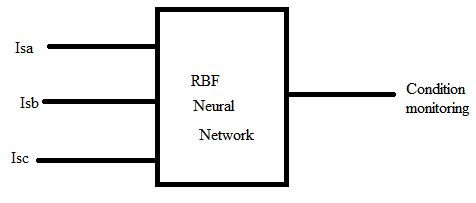 | Figure 5. Block diagram of the neural network |
5. Proposed Hybrid System
There are several ways to combine neural networks and fuzzy logic [5, 1]. These two technologies may be characterized by considering three main categories [5]* Auxiliary hybrid system;* Sequential Hybrid system;* Embedded Systems.The Adaptive Network based Fuzzy Inference System ANFIS implements a Takagi Sugeno fuzzy inference system [1]. It is a family of embedded system and it has five layers as shown in Figure 6 below [1].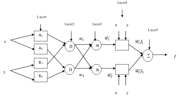 | Figure 6. ANFIS system [5] |
The first hidden layer is responsible for the mapping of the inputs variables relatively to each membership functions [5]. The second hidden layer to calculate the antecedents of the rules. The third hidden layer normalizes the rules strengths followed by the fourth hidden layer where the consequents of the rules are determined. The output layer calculates the global output as the summation of all the signals that arrive to this layer [5].A total of sixty numbers of data were used to train the system. The initial FIS Model used is the same FIS Model as used to create fuzzy logic. Figure 7 shows the training sequence (with 300 epochs) of the system with acceptable error and Figure 8 represents the proposed Hybrid system.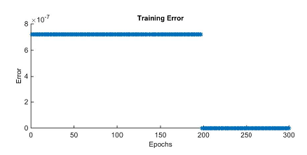 | Figure 7. Training ANFIS |
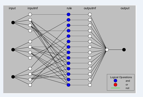 | Figure 8. Proposed hybrid system |
6. Results and Discussions
6.1. Healthy Motor
This simulation is done by applying a load torque of 50N.m at t=1s. When the motor starts, it current rises more than six time the rated current [12]. In this transient regime, that is between t=[0 0.5], diagnosis tools see this as fault and their outputs vary according to the values of currents. In other hand, when the motor is running at it permanent regime, root mean square values of motor currents Isa Isb and Isc are 19.22A. Figure 9 and Figure 10 presents the motor response in healthy conditions: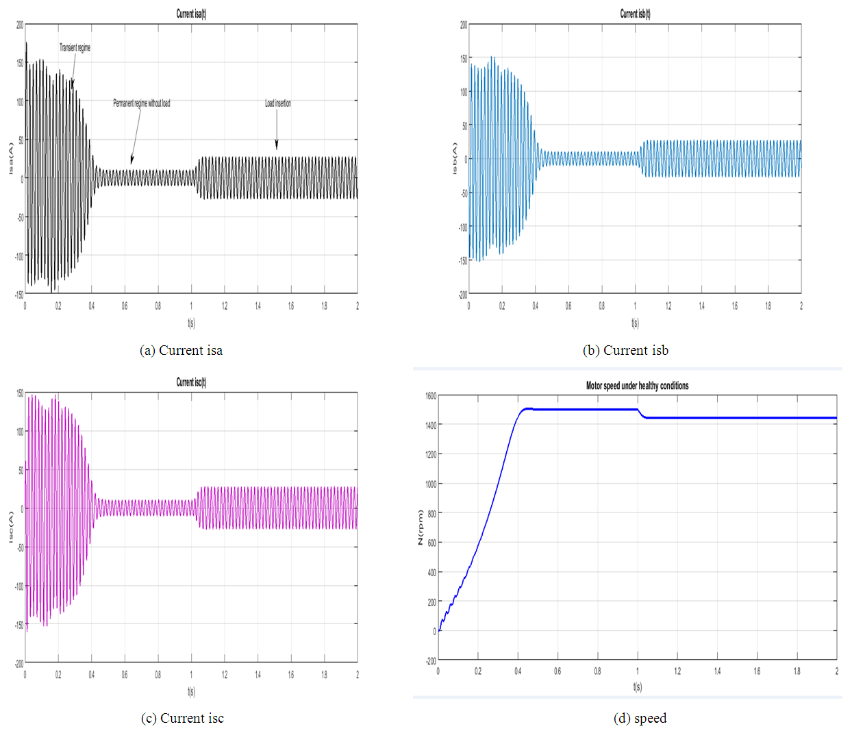 | Figure 9. Motor response in healthy conditions |
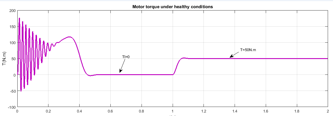 | Figure 10. Torque (Motor response in healthy conditions) |
6.2. Faulty Motor
This simulation is done by applying a load torque of 50N.m at t=1s when the motor is running. After load insertion, fault is occurred at t=1.5s.
6.2.1. Induction Motor under Phase Unbalance
When the motor starts normally, and runs at it permanent regime, load is inserted at t=1s, and then fault is occurred at t=1.5s. Phase (c) is maintained at normal voltage U=380V, phases (a) and (b) are respectively 693.51V and 571.4V, In other hand, ripples are observed on motor torque and motor speed.Figure 11 and Figure 12 presents the motor response under phase unbalance.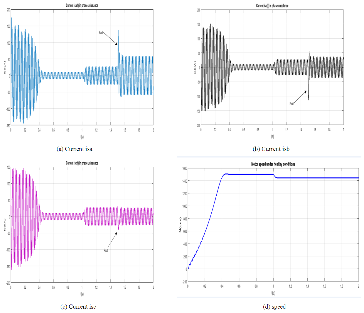 | Figure 11. Motor response under phase unbalance |
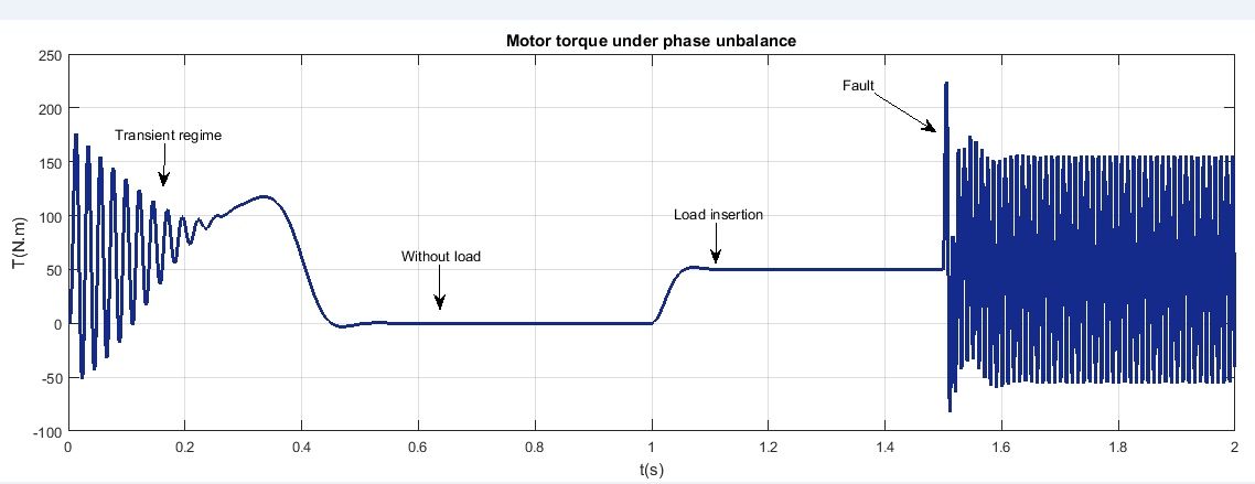 | Figure 12. Torque (Motor response under phase unbalance) |
6.2.2. Induction Motor under a Low Voltage
The motor was running normally when low voltage occurred. In this case, its performances are reduced. The process have to be sto pped. If not, increase in current will increase an overheating [7-12] and the motor will burn.Figure 13 and Figure 14 present the motor response under a low voltage.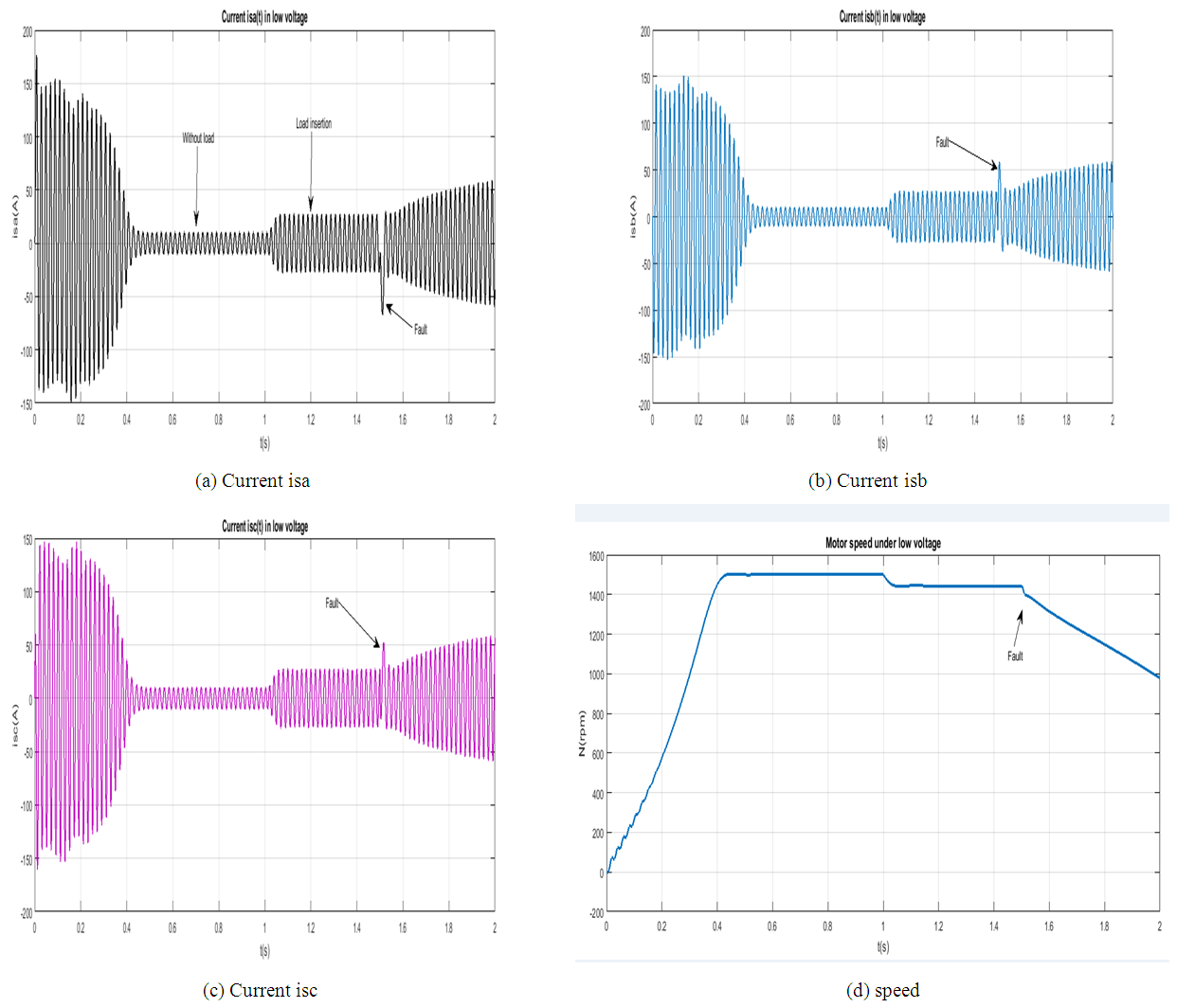 | Figure 13. Motor response under a low voltage |
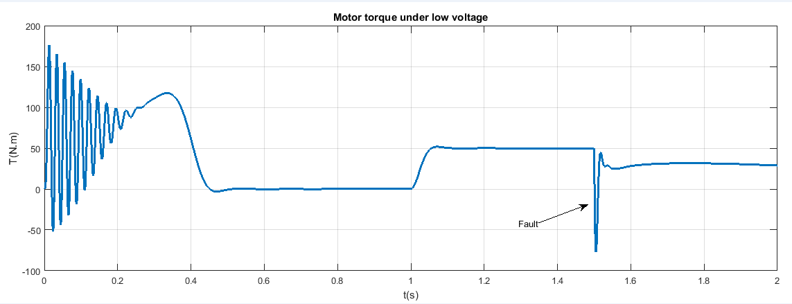 | Figure 14. Torque (Motor response under a low voltage) |
6.2.3. Induction Motor under a Critical Overload
This simulation is done by varying the load torque from zero (0) to 3Tn (Tl=[0 150] N.m). Increase in load increases motor currents and decreases speed. When the motor is overloaded, the motor torque increases and then decreases highly until the motor stop running, speed is equal to zero (N=0) at t=2.2s and the motor attempts to turn in reverse.Figure 15 and Figure 16 present the motor response under a critical overload.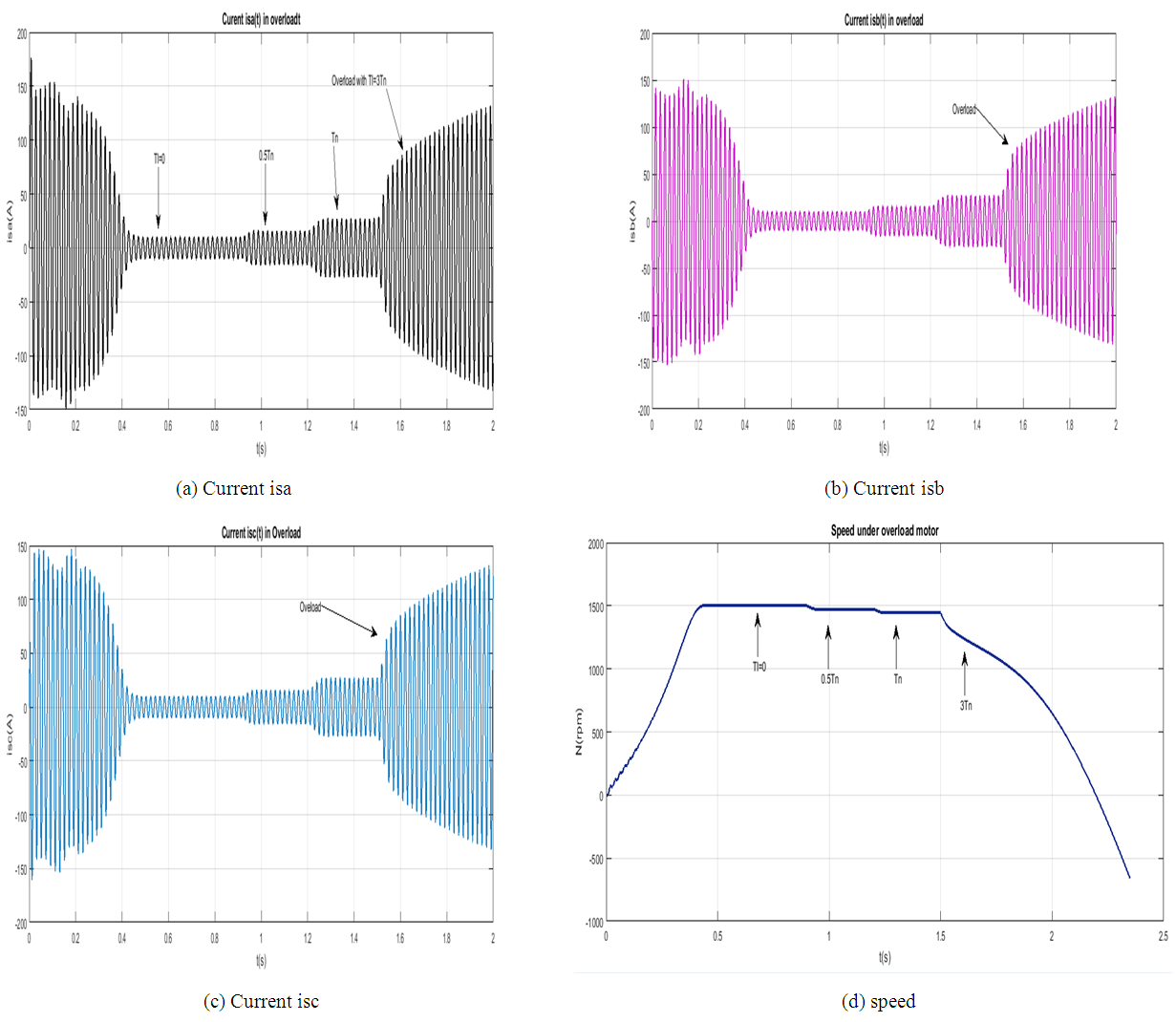 | Figure 15. Motor response under a critical overload |
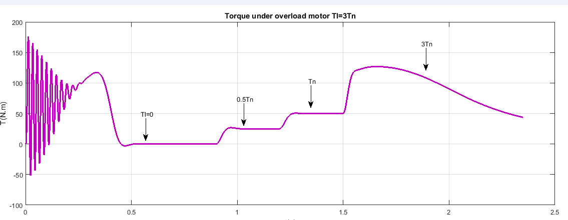 | Figure 16. Torque (Motor response under a critical overload) |
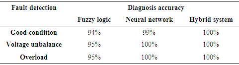
Table 3 show the comparative study among different tools observers. This is about the rate of detecting fault when it is occurred.Table 3. Diagnosis accuracy
 |
| |
|
From Table 3, the following conclusion can be derive: Fuzzy logic detect the stated faults at 95 percents while Artificial neural network and hybrid system detect at 100 percents. This depends on how they are trained. Furthermore, combining the two methods is more advantage than one method itself.
7. Conclusions
This research work has successfully presented a fault diagnosis of an induction motor based on fuzzy logic and artificial neural network. Additionally, an hybrid system were proposed to combine both system. A method of using fuzzy logic, neural network and hybrid system to interpret root mean square currents of induction motor for its conditions was presented. Correctly processing theses root mean square currents and inputting them to a fuzzy decision, neural network and neuro-fuzzy system achieved high diagnosis accuracy. However, the exact architecture of designing artificial intelligence techniques is not known in advance. It is usually obtained after a trial-and-error procedure. The performances of a such a system depend on the quality of rule, training data an so on.
References
| [1] | Ajith Abraham and Baikunth Nath. Hybrid intelligent systems design: A review of a decade of research. IEEE Trans-actions on Systems, Man and Cybernetics (Part C), 3(1): 1–37, 2000. |
| [2] | Rashi Aggarwal and Rajendra Kumar. Effect of training functions of artificial neural networks (ann) on time series forecasting. International Journal of Computer Applications, 109(3), 2015. |
| [3] | D Aguglia. Identification des paramètres du moteur a induction triphasé en vue de sa commande vectorielle (french text). 2002. |
| [4] | Abdel Ghani Aissaoui and Ahmed Tahour. Application of fuzzy logic in control of electrical machines. In Fuzzy Logic-Controls, Concepts, Theories and Applications. InTech, 2012. |
| [5] | Chennakesava R Alavala. Fuzzy logic and neural networks: basic concepts & application. New Age International, 2008. |
| [6] | Anand Bellure and MS Aspalli. Dynamic dq model of induction motor using simulink. International Journal of Engineering Trends and Technology (IJETT), 24(5):252–257, 2015. |
| [7] | MEH Benbouzid and H Nejjari. A simple fuzzy logic approach for induction motors stator condition monitoring. In Electric Machines and Drives Conference, 2001. IEMDC 2001. IEEE International, pages 634–639. IEEE, 2001. |
| [8] | Gabriel Buche. Commande vectorielle de machine asynchrone en environnement temps r´eel Mat- lab/Simulink. PhD thesis, 2001. |
| [9] | Unida Izwani Md Dun. Fault Detection in Three Phase Induction Motor Using Artificial Intelligence. PhD thesis, UMP, 2010. |
| [10] | Damian Giaouris, John Finch, Salah Ethni, Idirs Musa, Amr Ashoush, and Ayman Samy. An intro- duction to artificial intelligence and its applications to electric drives. |
| [11] | Rolf Isermann and Peter Balle. Trends in the application of model-based fault detection and diagnosis of technical processes. Control engineering practice, 5(5):709–719, 1997. |
| [12] | Greety Jose and Victor Jose. Fuzzy logic based fault diagnosis in induction motor. In 14th National Conference on Technological Trends (NCTT), pages 150–156, 2013. |
| [13] | Heikki N Koivo. Neural networks: Basics using matlab neural network toolbox. Author Website, 2008. |
| [14] | Jarmo Lehtoranta and Heikki N Koivo. Fault diagnosis of induction motors with dynamical neural networks. In Systems, Man and Cybernetics, 2005 IEEE International Conference on, volume 3, pages 2979–2984. IEEE, 2005. |
| [15] | Pankaj Mohindru and Nitika Sharma. A review: Fault diagnosis of stat using fuzzy logic technique. International Journal of Current Engineering Sciences, 2016. |
| [16] | Krzysztof Patan. Artificial neural networks for the modelling and fault diagnosis of technical processes. Springer, 2008. |
| [17] | SN Sivanandam, Sai Sumathi, SN Deepa, et al. Introduction to fuzzy logic using MATLAB, volume 1. Springer, 2007. |
| [18] | Jaroslava Žilková, Jaroslav Timko, and Peter Girovský. Nonlinear system control using neural net- works. Acta Polytechnica Hungarica, 3(4):85–94, 2006. |

 Abstract
 Reference
 Full-Text PDF
 Full-text HTML